

LeeBoy 7000 Parts Manual
PARTS
MANUAL
7000
Conveyor
Paver
Manual
No.
7000102
USER'S REFERENCE INFORMATION
DELIVER
DATE
_
TYPE
ENGJNE~
_
DEALER'S NAME & ADDRESS
EQUIPMENT
SERIAL
NO. _
ENGINE NO
•.
_
EQUIPMENT HOURS
---------
SAFETY NOTICE
All
danger
points
about
the
7000
are
explained and labeled by
decalstothe
best of
our
knowledqe, If
anyone in
the
field
discovers
anything omitted, please notify
your
closest
dealerorfactory.

£
••
'-,
ONE
YEAR
LIMITED
WARRANTY
EFFECTIVE
FOR
UNITS
SHIPPED
AFTER
DECEMBER1,2001
LeeBoy
688 North
Highway
16
Denver,
North
Carolina 28037
www.LeeBoy.com
,
WARRANTY
1. If a defect in material or workmanship is found and the
authorized dealer is notified during the warranty period, LeeBoy
will repair or replace any part or component
of
the unit or part
that fails to conform to the warranty during the warranty period.
2. The warranty date
will
begin upon the completionofthe
warranty form by the initial customer and
will
expire after
twelve (12) months have passed. The Warranty Card should
be filled out
within
(10) days of delivery of the unit.
3. Engines are warranted by their manufacturers and
may
have
warranty coverage that differs
from
thatofLeeBoy.
4. Replacement parts furnished by LeeBoy are covered
for
the
remainder of the warranty period applicable to the
unit
or
component in which such parts are installed.
5. LeeBoy has the right to repair any component or part before
replacing it with a new part.
6. All
new
replacement parts purchased by a LeeBoy dealer
will
carry a six (6) month warranty. Remanufactured parts purchased
by a LeeBoy dealer will carry a ninety (90)day warranty.
LIMITATIONS
LeeBoy has no obligation under this warranty for:
1. Any defects caused by misuse, misapplication, negligence,
accident or failure to maintain or use in accordance
with
the
most
current operating instructions.
2. Unauthorized alterations.
3. Defects or failures caused by any replacement parts or
attachments
not
manufactured by or approved by LeeBoy.
4. Failure to conduct normal maintenance and operating
service, including
without
limitation, providing lubricants,
coolant, fuel, tune-ups, inspections or adjustments.
5. Unreasonable delay, as established by LeeBoy, in making
- the applicable units or parts available upon notification of
a service notice ordered by LeeBoy.
6. The warranty responsibility on all engines rests with the
respective manufacturer.
7. LeeBoy
may
have support agreements
with
some engine
manufacturers
for
warranty and parts support.
ITEMS
NOT
COVERED
LeeBoy is not responsible for the following:
1. Charges
for
travel time, mileage, or overtime.
2. Charges related to transporting the product to and
from
the
place at which warranty
work
is performed.
3. Airfreight charges related to transporting repair parts to
the
place at which warranty
work
is performed.
4. All used units or used parts
of
any kind.
5. Repairs due to normal wear and tear, or brought about by abuse
or lack
of
maintenance of the equipment, except for premature
failures, conveyor chains, polytrack pads, and track rails.
6. Attachments
not
manufactured or installed by LeeBoy.
7. Liability
for
incidental or consequential damages of any type,
including, but not limited to lost profits or expenses of acquiring
replacement equipment.
8. Miscellaneous charges.
OTHER WARRANTIES
THE
FOREGOING
WARRANTYISEXCLUSIVE
AND IN
LIEU
OFALL
OTHER
EXPRESSED,
STATUATORY
AND
IMPLIED
WARRANTIES
APPLICABLE
TO UNITS,
ENGINES,ORPARTS
WITHOUT
LIMITATION,
ALL
IMPLIED
WARRANTIES
OF
MERCHANTABILITYORFITNESS
FOR
ANY
PARTICULAR
USEOR
PURPOSE.
IN NO
EVENT,
WHETHER
AS A
RESULTOFBREACHOFCONTRACT
OR
WARRAN~
OR
ALLEGED
NEGLIGENCEORLIABILITY
WITHOUT
FAULT,
SHALL
LEEBOYBELIABLE
FOR
SPECIAL,
INCIDENTALORCONSEQUENTIAL
DAMAGES,
INCLUDING
WITHOUT
LIMITATION,
LOSSOF
PROFITORREVENUE,
COSTOF
CAPITAL,
COSTOF
SUBTITUTED
EQUIPMENT,
FACILITIESORSERVICES,
DOWNTIME
COSTS,
LABOR
COSTS
ORCLAIMSOF
CUSTOMERS,
PURCHASERS
OR
LESSEES
FOR
SUCH
DAMAGES.
Index
GENERAL
STATEMENT .•.......................................................................................................1
IMPORTANT
SAFETY
INSTRUCTIONS ...........................................•.................................... 2
SAFETY
PRECAUTIONS ..................................................................•....................................3
SPECIFICATIONS..................................................•.............................•..................................
4
SAFETY
PRECAUTIONS
AND
GENERAL
INFORMATION 5
PRE-START INSPECTION........................................................•.........•........•.................
5
OPERATING
SAFETY
..•......................................•.•.................•..•......•........•.................5
STOPPING
SAFETY
....•...........................................................•...................................5
MAINTENANCE
SAFETY
..................................•.........................................................5
CONTROLS
AND
DESCRIPTIONS 6 & 7
STARTING
THE
ENGINE ..•.....................................................•..........•..........•........................ 8
PRELIMINARY .•......•....................................................••...................•..........................8
ENGINE/START-UP ....•..............................................•.................................................8
STOPPING
THE
ENGINE (Diesel
Engine)
8
PAVER DRIVING INSTRUCTIONS 8
TRUCK
HITCH ATTACHMENT (OPTIONAL) 9
PAVER PREPARATION INSTRUCTIONS 10
BURNER
IGNITION PROCEDURES .........................•..•...............•............................10
IF
BURNERS
DON'T
IGNITE "10
MANUAL
LIGHTING OF BURNERS...............................................................•..........11
OPERATING FEEDER ••................•........................•.................•.................................12
OPERATION
OF ELECTRIC
FLIGHT
SCREW 13
USE
OF
AUGER
EXTENSIONS ...................................•.............................................13
OPERATION
OF HYDRAULIC CUTOFFS 14
ELECTRIC
SPRAYDOWN 14
AUTOMATIC
AUGER
14
AUTOMATIC
AUGER:
NEW
STYLE
(Tiedinwith
Conveyors)
15
HOW
TO OPERATE 15
LOADING
AND
UNLOADING 16
TIE DOWN PROCEDURES
17
PAVER PREPARATION INSTRUCTIONS 18
STARTING TO PAVE 18
SETTING SCREE·D
TO
PAVE 19
SETTING SCREED ENDGATES 20
SETTING SCREED EXTENSIONS (Used
When
Paving
Over8Feet)
21
PAVER OPERATION 21
ROUTINE MAINTENANCE
10 -
HOUR
OR DAILY ROUTINE MAINTENANCE 22
50 -
HOUR
OR
WEEKLY
ROUTINE MAINTENANCE
.:
22
100
- HOUR OR MONTHLY ROUTINE MAINTENANCE 23
250 HOUR OR
QUARTERLY
ROUTINE MAINTENANCE 24
500 - HOUR OR SEMI-ANNUAL ROUTINE MAINTENANCE 24
1000 - HOUR
OR
ANNUAL
ROUTINE MAINTENANCE 24
i

Index (Continued)
LUBRICATION
CHART
•..•••••...•.....................•..•..............•.•••..•.........•................••.•••....••.•.....25
MAINTENANCE
ADJUSTMENTS
.....................•.........•........................................................26
TO RAISE FEEDERS ...•.......•......................•.........•....................................•...............26
LOWERING
FEEDERS •............................................................................................. 27
FEEDER
FLIGHT
CHAIN
ADJUSTMENT
27
AUTOMATIC
TRACK
ADJ
USTMENT ...................•....................................................27
DIRECTIONAL CONTROL ADJUSTMENTS 28
FORWARD OR REARWARD (CABLE CORRECTION) 28
FEEDER DRIVE CHAIN ........................................•..............................................•..... 28
AUGER
DRIVE CHAIN ..........................................•.........•...•......................................28
CONVEYOR
LIMIT SWITCH 29 & 30
ELECTRIC
DIAGRAM
FOR
7000
PAVER .........•.•.••.•......•..•.•.•..•....•.•.....•......•....•..•..............31
HYDRAULIC
DIAGRAM
FOR
7000
PAVER ....................•.•.••.•.......•..............•.•..•••..........•.•..32
TROUBLE
SHOOTING
GUiDE
33 & 34
Ii

REAR VIEW
MODEL
7000
LOW
DECK
ASPHALT PAVER
OPERATORS,
MAINTENANCE
AND
PARTS
MANUAL
This
manual
shouldbe usedwithall relatedsupplemental
books,
engine
and
transmission
manuals,
andparts
books.
Related
service
Bulletins
should
be reviewed to
provide
information
regarding
some
ofthe recent
changes.
Ifanyquestions arise
concerning
thispublicationor
others,
contact your local Lee-Boy Distributor for the latest
available information.
Contents
ofthis
manual
are
based
oninformation in effect
atthetimeofpublication
andaresublecttochangewithout
notice.
FRONT 3/4 VIEW
1
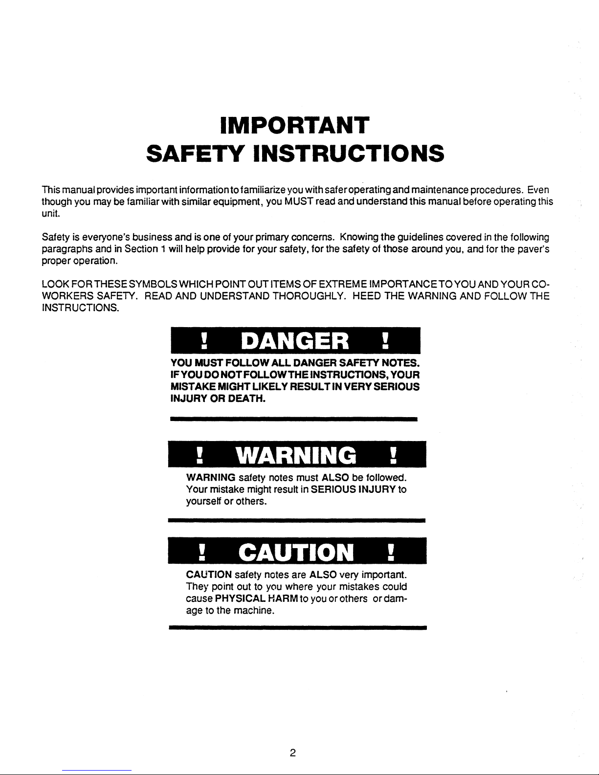
IMPORTANT
SAFETY
INSTRUCTIONS
Thismanualprovidesimportantinformationtofamiliarize youwith saferoperatingand maintenanceprocedures. Even
though you may be familiar with similar equipment, you
MUST
read and understandthis manual before operating this
unit.
Safety is everyone's business and is one of your primary concerns. Knowingthe guidelines covered in the following
paragraphs and in Section 1 will help provide for your safety, for the safety of those around you, and for the paver's
proper
operation.
LOOKFORTHESESYMBOLSWHICH POINTOUTITEMSOF EXTREMEIMPORTANCETO YOUANDYOUR CO-
WORKERS SAFETY. READ AND UNDERSTAND THOROUGHLY. HEED THE WARNING AND FOLLOW THE
INSTRUCTIONS.
!
DANGER
!
YOU MUST FOLLOW
ALL
DANGER SAFETY NOTES.
IFYOUDONOTFOLLOWTHE
INSTRUCnONS,
YOUR
MISTAKEMIGHT LIKELYRESULT INVERY SERIOUS
INJURY OR DEATH.
! WARNING !
WARNING safety notes must
ALSO
be followed.
Your mistake might result in SERIOUS
INJURY
to
yourself or others.
! CAUTION !
CAUTION safety notes are
ALSO
very important.
They point out to you where your mistakes could
cause PHYSICAL
HARM
to you or others or
dam-
ageto the machine.
2
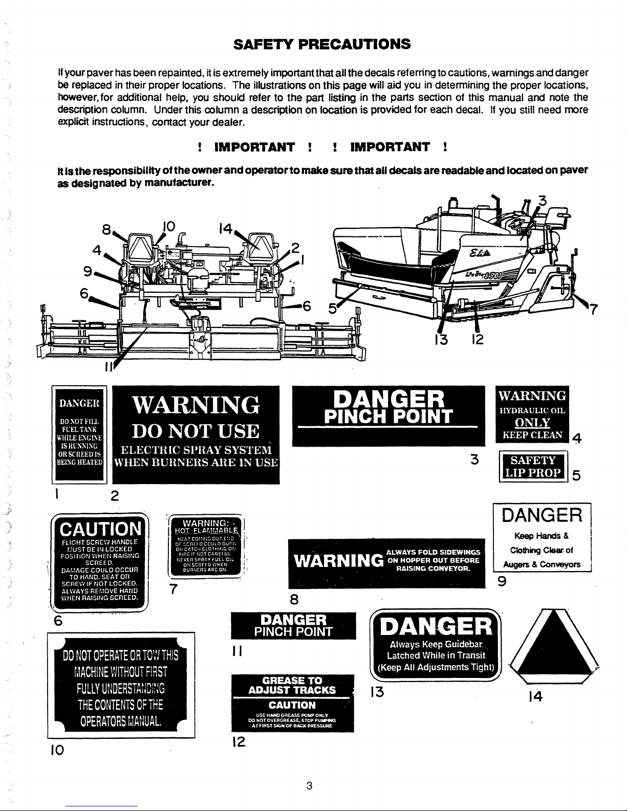
SAFETY
PRECAUTIONS
If
your
paver
has been repainted, itis extremely importantthatall
the
decalsreferringto cautions,warnings and
danger
be replaced in their
proper
locations. The illustrations on this
page
will aid you in determining
the
proper locations,
however,
for
additional help, you should refer to
the
part listing in the parts section of this
manual
and note the
description column. Under this
column
a description on location is provided
for
each decal. If you still need more
explicit instructions, contact your dealer.
!
IMPORTANT
!
!
IMPORTANT
!
ItIs
the
responsibilityofthe
owner
and
operatorto
make
sure
that
all
decals
are readable
and
locatedon paver
as designated by manufacturer.
WARNING
IIYDRAULIC OIL
!lliLX
KEEP
CLEAN
8
4
9
6
2
6
DANGER
PINCH POINT
3
4
1-15
7
CAUTION
fLIGHTSCREW
HANDLE
rJUST DE IN
LOCKED
POSITION WHEN RAISING
SCREED.
DAr."~GE
COULD OCCUR
TO HAND.
SEAT
on
5CRE\.v IF NOT LOCKED.
Al\VAVS
REr.10VE
HAND
WHEN RAISING·SCFlE£O.
WARNING: .l.
tlOI
ELAr.1M~BL~
HE.'\T
cor.~lIiG
OUT
eJD
~
or scner 0 COULO nunr.
011 c.ncil
CLOTHIr~G
orJ
finE
rr NOT CAREfUL.
fJEVEn SPRAY
Furl
ou
mJscnrro WHEtJ
sunurns ARE on.
W
'
A-.
RNI
NG·
ALWAYS
FOLD
SIDEWINGS
~
ON
HOPPER
OUT
BEFORE
..
RAISING CONVEYOR.
8
DANGER
Keep Hands&
Clothing Clear-of
Augers & Con\l9Yors
9
6
DO
NOT
OPERATEORTO\V
THIS
MACHINE
VIITHOUT
FIRST
FULLY
UNDERSTAiJDlrJG
THE
CONTENTS
OF
THE
OPERATORS
r.1ANUAL.
10
II
GREASE TO
ADJUST
TRACKS
---.-.
CAUTION
USE HAND GREASE PUMP ONLY
00
NOT OVERGREASE., STOP
PUIFINO
ATFIRST SKiN OF BACK
PRESSUR£
12
3
13
14
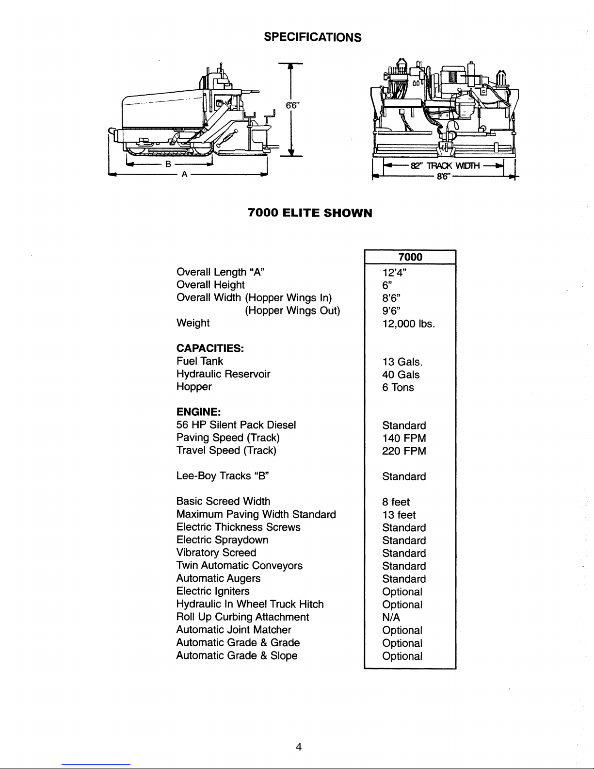
SPECIFICATIONS
-------A--------.
T
6'6"
82"
lRACK
VVI(JTH
~
I
-.....----
8'6"--~
7000
ELITE
SHOWN
7000
Overall Length "A"
Overall Height
Overall Width (Hopper Wings In)
(Hopper
Wings
Out)
Weight
CAPACITIES:
Fuel Tank
Hydraulic Reservoir
Hopper
ENGINE:
56
HP Silent Pack Diesel
Paving Speed (Track)
Travel Speed (Track)
Lee-Boy Tracks "B"
Basic Screed Width
Maximum Paving Width Standard
Electric Thickness Screws
Electric Spraydown
Vibratory Screed
Twin Automatic Conveyors
Automatic Augers
Electric Igniters
Hydraulic In Wheel Truck Hitch
Roll Up Curbing Attachment
Automatic Joint Matcher
Automatic Grade
&Grade
Automatic Grade & Slope
4
12'4"
6"
8'6"
9'6"
12,000Ibs.
13 Gals.
40
Gals
6 Tons
Standard
140 FPM
220 FPM
Standard
8 feet
13 feet
Standard
Standard
Standard
Standard
Standard
Optional
Optional
N/A
Optional
Optional
Optional
SAFETY
PRECAUTIQNS
AND
GENERAL
INFORMATION
PRE-START INSPECTION
INSPECTmachine. Haveany malfunctioning, broken
or
missing parts corrected or replaced before using.
Hydraulichoses shouldbe checkeddaily
forwearand
leaks. Replaceifdamaged.
CHECKthatallthe instructionandsafety labelsarein
place and readable. These are as important as any
other equipmenton the machine.
READand FOLLOWall instruction
decals.
WEAR OSHA required safety equipment when runningthe paver.
FILLthe fueltankwiththe engineoff.Neverfillnearan
openflame,when smokingorwhenscreed heatison.
CLEAR auger
&feeders before startingengine.
Make
sure
allcovers andguards arein place.
OPERATING
SAFETY
ALWAYS make sure no person or object is in your
lineof travelBEFORE
starting.
WORK slowlyin tight areas.
DO
NOT
run
engine in a closed building for long
perio°ds
of time. NEVER spray fuel oil on or near
screedwhile
it is being heated.
AVOIDsteephills
ifpossible
DONOT shifttransmissions on steepgrades.
ALWAYS look BEFORE changing your direction
of
travel.
NEVER open a valve to burner unless a flame is
present. Heat screed for no more than
5·
minutes.
Makesureallvalvesareclosed afterburneristurned
off.
AVOID leaving engine running without operator
present.
5
STOPPING
SAFETY
ALWAYS park the paver on solid, level ground, in low
range. IFthis is not possible, alwaysparkthe
paverata
right angle to the slope. Lower screedwhen parked.
USEproperflags, barriersandwamingdevicesespecially
when parking in areas of traffic.
MAINTENANCE
SAFETY
AVOIDworking on the paverwith the engine running.
NEVERfill the fuel tank with the engine running.
DO NOT change the engine governor settings.
ALWAYS replace damaged or lost decals.
DISCONNECT battery
cables when working on the
electrical system or when weldingon the unit.
IF battery needs a charge be
sure battery charger is off
when making connections.
BESUREthecorreetbatterypolarityisobserved(negative
(-) to negative (-) and positive
(+) to positive
(+»
when
connecting a battery charger or jumper cable.
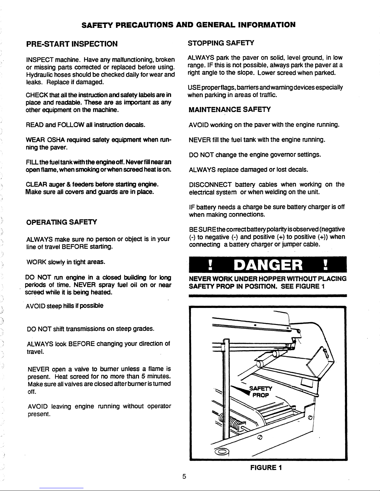
!
DANGER
!
NEVERWORK UNDER HOPPERWITHOUTPLACING
SAFETY PROP IN POSITION. SEE FIGURE 1
FIGURE 1
~B
.. . ....
VIEW
IN
BOX D
VIEW IN
BOX
F
6
25
~
....
--F
......
---
VIEW IN
~OX
C
21
20
19
18
1752'53
43
VIEW
IN'
DIRECTION OF
ARROW
A
...
------
....
~
26
45
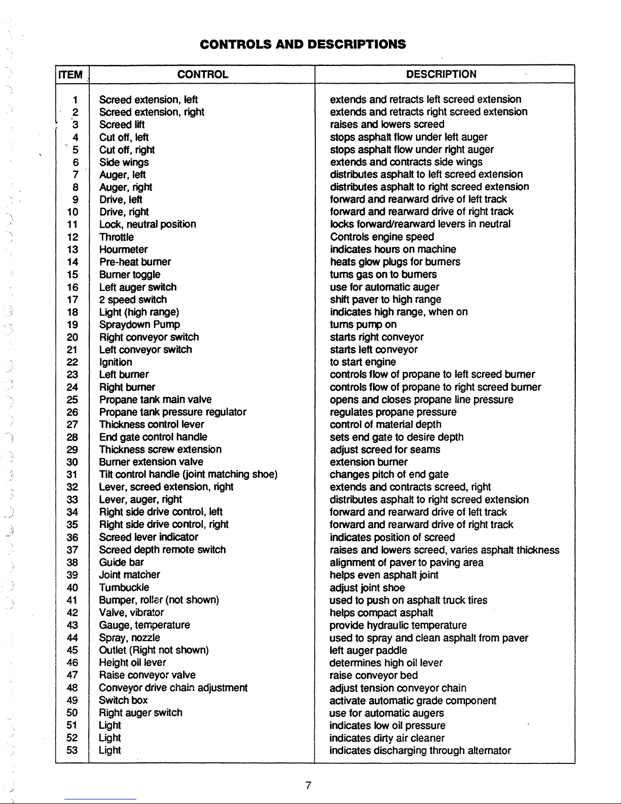
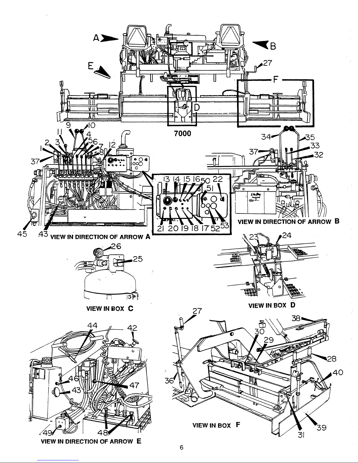
CONTROLS AND DESCRIPTIONS
ITEM
CONTROL
DESCRIPTION
1
SCreed
extension,
left
extends
and
retracts
left
screed
extension
2
SCreed
extension,
right
extends andretracts right
screed
extension
3
Screed
lift
raisesandlowers
screed
4 Cutoff, left
stopsasphalt flow underleftauger
".::
5
Cutoff, right
stopsasphaltflow underrightauger
6
Sidewings
extends andcontracts sidewings
7
Auger,
left
distributes asphaltto left
screed
extension
8
Auger,
right
distributes asphaltto right
screed
extension
9
Drive,
left
forward
and
rearward
driveof lefttrack
10
Drive,
right
forwardand
rearward
driveof righttrack
11
Lock,
neutral
position
locksforward/rearward
levers
inneutral
12 Throttle
Controls
engine
speed
13
Hourmeter
indicates hourson
machine
14
Pre-heat
burner
heatsglowplugsfor burners
15 Burner
toggle
tums gasonto bumers
16 Leftauger
switch
usefor automatic auger
17 2
speed
switch
shiftpaverto high
range
18
Light(high
range)
indicates high
range,
whenon
19
Spraydown
Pump
tumspumpon
20
Right
conveyor
switch startsrightconveyor
21
Left
conveyor
switch
startsleft conveyor
22
Ignition
to start
engine
23
Leftburner
controlsflow of
propane
to left
screed
burner
24
Right
burner
controlsflowof
propane
to right
screed
bumer
25
Propane
tankmainvalve opensandcloses
propane
line
pressure
26
Propane
tankpressure regulator
regulates propane
pressure
27
Thickness
control lever
controlof material depth
28
Endgatecontrol handle
setsendgateto desiredepth
29
Thickness
screwextension adjust
screed
for
seams
30
Burner
extension
valve
extension burner
31
Tin
control
handle
(joint
matching
shoe)
changespitchof endgate
32
lever,
screed
extension, right
extendsandcontracts
screed,
right
33
Lever,
auger,
right
distributes asphaltto right
screed
extension
34
Right
sidedrivecontrol, left
forwardand
rearward
driveof lefttrack
35
Right
sidedrivecontrol,
right
torwardand
rearward
driveof
right
track
36
Screed
leverindicator
indicatesposition of
screed
37
SCreed
depth
remote
switch
raisesandlowers
screed,
varies
asphalt
thickness
38
Guide
bar
alignment of paverto pavingarea
I
39
Joint
matcher
helpsevenasphaltjoint
I
40
Turnbuckle
adjustjointshoe
i
41
Bumper,
roller(not
shown)
usedto pushon asphalttrucktires
I
42
Valve,
vibrator
helpscompact asphalt
43
Gauge,
temperature
providehydraulic temperature
44
Spray,
nozzle
usedto sprayand
clean
asphalt
frompaver
i
45
Outlet
(Right
not
shown)
leftaugerpaddle
I
46
Height
oillever
determines highoil lever
47
Raise
conveyor
valve
raiseconveyor bed
48
Conveyor
drivechain
adjustment
adjusttensionconveyorchain
49
Switch
box
activateautomatic grade
component
50
Right
auger
switch
usefor automatic
augers
51
Light
indicateslowoil
pressure
52 Light
indicatesdirtyair cleaner
53
Light
indicatesdischarging through alternator
7
STARTING
THE
ENGINE
PRELIMINARY
Before you start the engine:
A. Check fuel level and check lines and tank
for
leaks.
B. Check crankcase oil level.
!
CAUTION·
!
FAILURE TO MAINTAIN CORRECT OIL LEVEL IS
GREATEST
SINGLE
CAUSE
OF
ENGINE
FAILURES.
c.
Check
hydraulic
oil
level.
Oil
level
is
determined by petecek on hydraulic oil tank.
D.
Make
sure
steering
control
levers
are
in
the neutral position. To start,
the
safety latch
lever must
be in the latch position.
E.
Refer
to
engine
operators
manual
for
instructions
when
starting
engine
for
first
time.
Follow
engine
manufacturer's
recommendationsforfuelandoil.
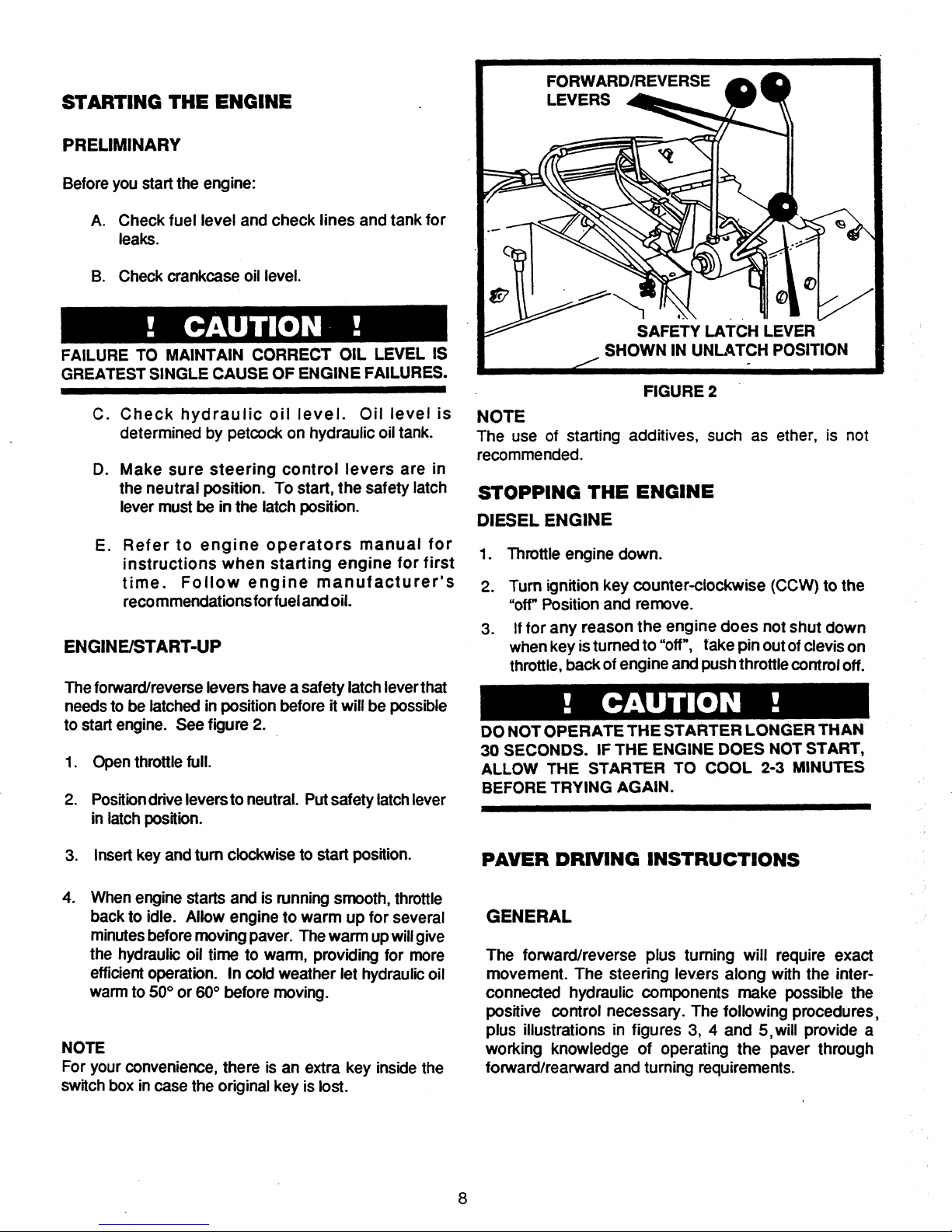
ENGINE/START-UP
Theforward/reverse levers have asafetylatch leverthat
needsto be latched in position before it will be possible
to start engine.
see
figure 2.
1. Openthrottle full.
2. Positiondrive leversto neutral. Putsafety latchlever
in latch position.
3. Insert key and turn clockwise to start position.
4. When engine starts and is running smooth, throttle
back to idle. Allow engine to warm up for several
minutesbeforemoving paver. The warm upwill give
the hydraulic oil time to
wann, providing for more
efficient operation. In cold weather let hydraulic oil
warm
to 500or 600before moving.
NOTE
For your convenience, there is an extra key inside the
switch box in case the original key is
lost.
8
FORWARD/REVERSE
LEVERS
~~
'.
SAFETY
LATCH
LEVER
SHOWNIN UNL6.TCH POSITION
FIGURE
2
NOTE
The use of starting additives, such as ether, is not
recommended.
STOPPING
THE
ENGINE
DIESEL ENGINE
1. Throttleengine down.
2. Turn ignition key counter-clockwise (CCW) to
the
"off" Position and remove.
3. Iffor
any
reason
the
engine
does
not
shutdown
whenkey is turnedto "off",. take pin out01clevis on
throttle, backof
engine
and pushthrottlecontrol off.
!
CAUTION
!
DO
NOTOPERATETHESTAATER
LONGER
THAN
30
SECONDS.
IF
THE
ENGINE
DOES
NOT
START,
ALLOW THE STARTER TO COOL 2-3 MINUTES
BEFORE
TRYING
AGAIN.
PAVER
DRIVING
INSTRUCTIONS
GENERAL
The forward/reverse plus turning will require exact
movement. The steering levers along with the interconnected hydraulic components make possible the
positive control necessary.
The following procedures,
plus illustrations in figures 3, 4 and 5,will provide a
working knowledge of operating the paver through
forward/rearward and turning requirements.
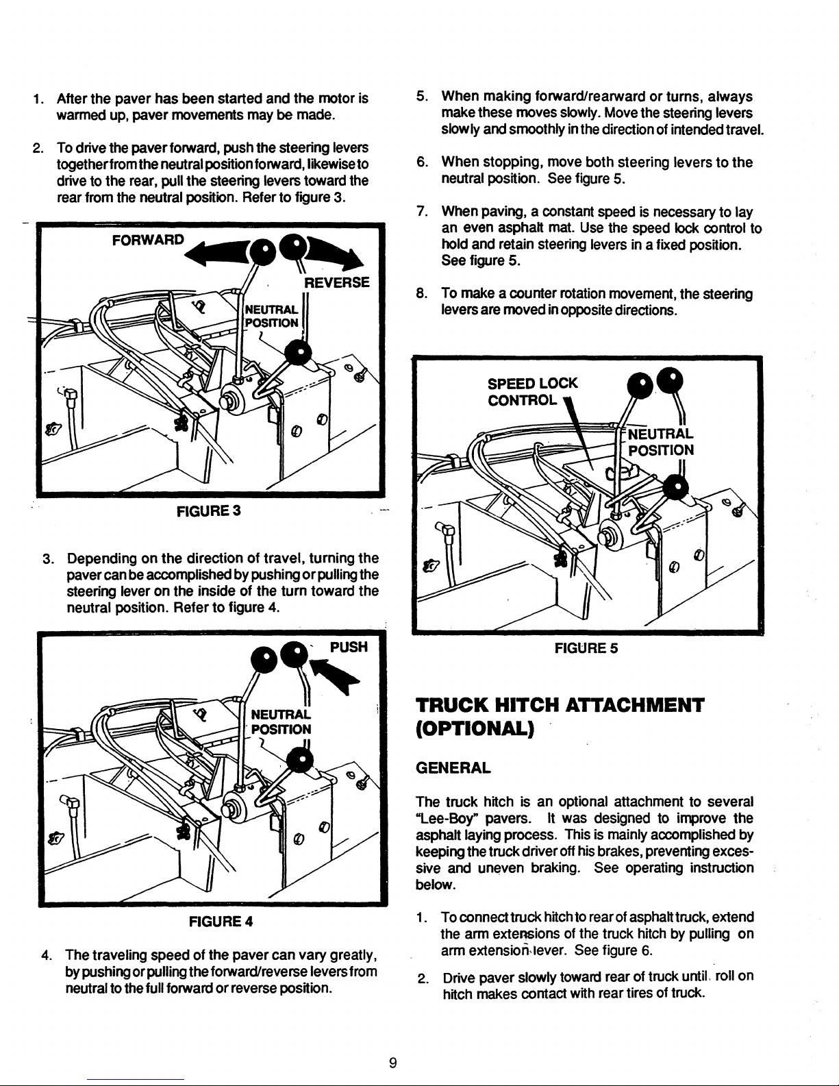
1. Afterthe paver has been started and the motor is
warmedup, paver movements maybe made.
5. When making forward/rearward or turns, always
makethese moves
sloWly.
Movethe steering levers
slowlyandsmoothlyinthedirectionofintendedtravel.
FIGURE4
FIGURES
6. When stopping, move both steering levers to the
neutralposition. Seefigure
5.
7. Whenpaving, a constant speedis necessary to lay
an even asphalt mat. Usethe speed lock control to
holdand retain steering leversin a fixedposition.
Seefigure
5.
8. To makeacounterrotation
movement,
the steering
leversaremovedinopposite directions.
1. Toconnecttruckhitchto rearofasphalttruck,extend
the arm extensionsof the truck hitchby pulling on
arm
extensoruever. Seefigure 6.
2. Drivepaver slowlytowardrearof truck
until. roll on
hitchmakescontactwith reartiresof truck.
TRUCK
HITCH
ATTACHMENT
(OPTIONAL)
GENERAL
The truck hitch is an optional attachment to several
"Lee-Boy" pavers. It was designed to improve the
asphaltlayingprocess. Thisis mainlyaccomplished by
keepingthetruckdriveroffhisbrakes,preventing exces-
sive and uneven braking. See operating instruction
below.
ct-.
REVERSE
FIGURE3
FORWARD~
3. Depending on the direction of travel, turning the
pavercanbeaccomplished bypushingorpullingthe
steeringleveron the inside of the turn toward the
neutral position. Refer to figure
4.
4. Thetraveling speedof the paver can vary greatly,
bypushingorpullingtheforward/reverse leversfrom
neutraltothefullforwardorreverseposition.
2. Todrivethepaverforward,pushthe steering
levers
togetherfromtheneutralpositionforward,likewiseto
driveto the rear,pull the steeringleverstowardthe
rearfrom the neutralposition.Referto figure
3.
9
FIGURE
6
3. Retract
the
arm
extensions until
both
guide rollers
are fully locked into
truck
wheel rims.
4. May be necessary to adjust the rollerguides to the
inside of the wheel rims, initially.
See
figure 7.
FIGURE 7
10
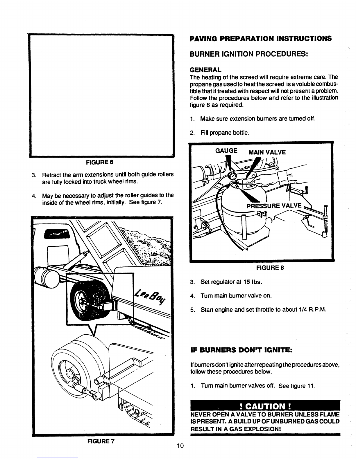
PAVING PREPARATION INSTRUCTIONS
BURNER IGNITION PROCEDURES:
GENERAL
The heating of
the
screed will require extreme care. The
propane
gas
used
to heat
the
screed
is a voluble combus-
tible
thatiftreated
with
respect
will
not
present a problem.
Follow
the
procedures
below
and
refertothe
illustration
figure 8 as required.
1. Make sure extension burners are turned off.
2. Fill propane bottle.
GAUGE
FIGURE 8
3.
Set
regulator at 15
Ibs.
4.
Tum
main
burner
valve on.
5. Start engine
and
set throttle to about 1/4 R.P.M.
IF BURNERS DON'T IGNITE:
Ifburners
don't
igniteafter repeating
the
proceduresabove,
follow these procedures below.
1.
Tum
main
burner
valves off.
See
figure 11.
, !
CAUTION!
NEVER
OPEN
A
VALVE
TO
BURNER
UNLESS
FLAME
IS
PRESEtjT.ABUILD
UP OF
UNBURNED
GAS
COULD
RESULT IN A
GAS
EXPLOSION!
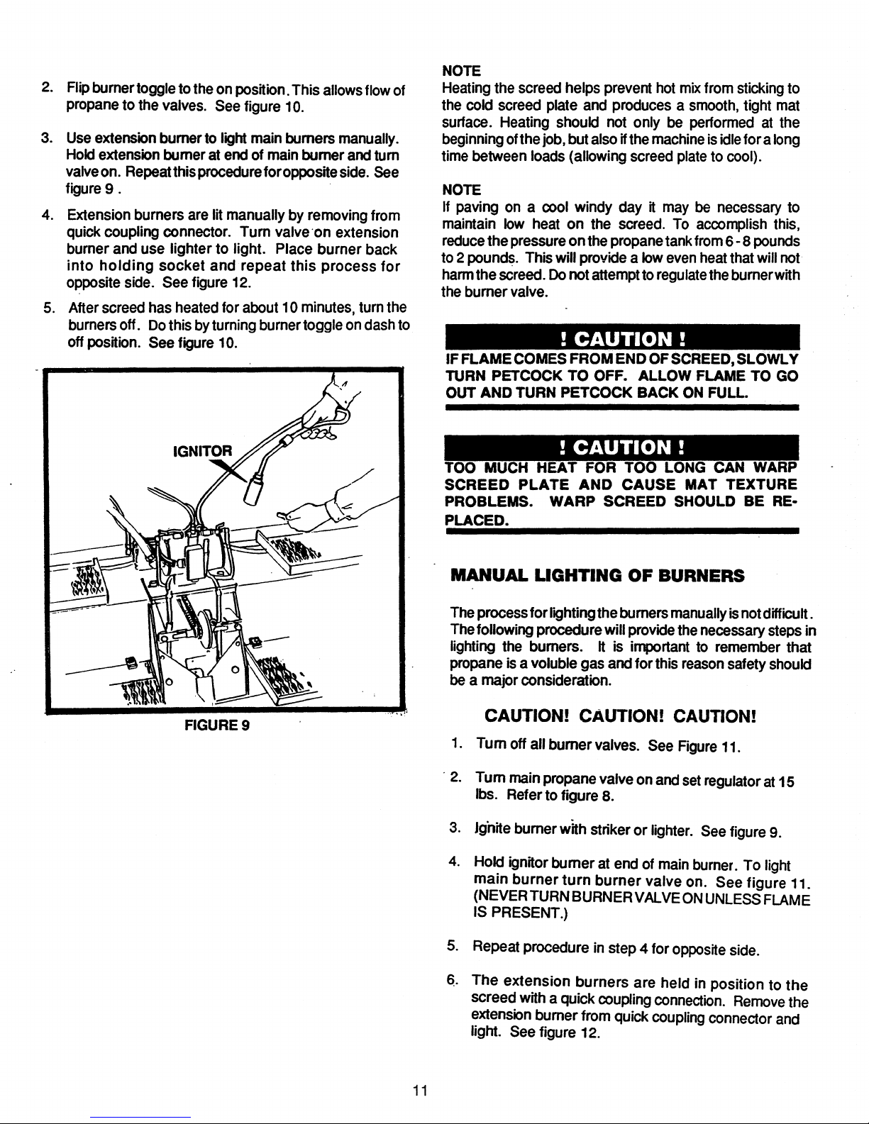
2. Flipburnertoggletothe onposition.This allowsflowof
propaneto the valves. Seefigure 10.
3. Useextensionbumerto light mainbumers manually.
Hold extensionbumer at end of mainburner andtum
valveon. Repeatthisprocedureforoppositeside.see
figure
9 .
4. Extensionburners arelit manuallyby removingfrom
quickcoupling connector. Turn valve
'on extension
burner and use lighter to light. Place burner back
into
holding
socket and repeat this process
for
oppositeside. Seefigure 12.
5. Afterscreedhas heatedfor about10 minutes,turnthe
burnersoff.
Dothis byturningburnertoggleondashto
offposition. Seefigure
10.
.....
',",.
FIGURE9
11
NOTE
Heatingthe screedhelps preventhotmixfrom sticking to
the cold screed plate and producesa
smooth,
tight mat
surface. Heating should not only be performed at the
beginningofthejob,butalso
ifthe
machine
isidleforalong
timebetween loads(allowing screedplateto cool).
NOTE
If paving on a 0001 windy day it may be necessary to
maintain
low heat on the screed. To accomplish this,
reduce
thepressureonthepropanetankfrom6 -8 pounds
to2 pounds. This will providea lowevenheatthatwill not·
harmthescreed.
Donotattempttoregulatetheburnerwith
the burnervalve.
!
CAUTION!
IFFLAMECOMES FROM ENDOF
SCREED,
SLOWLY
TURN PETCOCK TO OFF. ALLOW FLAME TO GO
OUT AND TURN PETCOCK BACK ON FULL.
!
CAUTION!
TOO MUCH HEAT FOR TOO LONG CAN WARP
SCREED
PLATE
AND
CAUSE
MAT
TEXTURE
PROBLEMS. WARP SCREED SHOULD BE REPLACED.
MANUAL
LIGHTING OF BURNERS
Theprocessforlightingtheburnersmanuallyisnotdifficult.
Thefollowingprocedurewillprovidethenecessarystepsin
lighting the burners.
It is important to remember that
propaneisa volublegas andfor this
reason
safetyshould
be a majorconsideration.
CAUTION! CAUTIONI CAUTION!
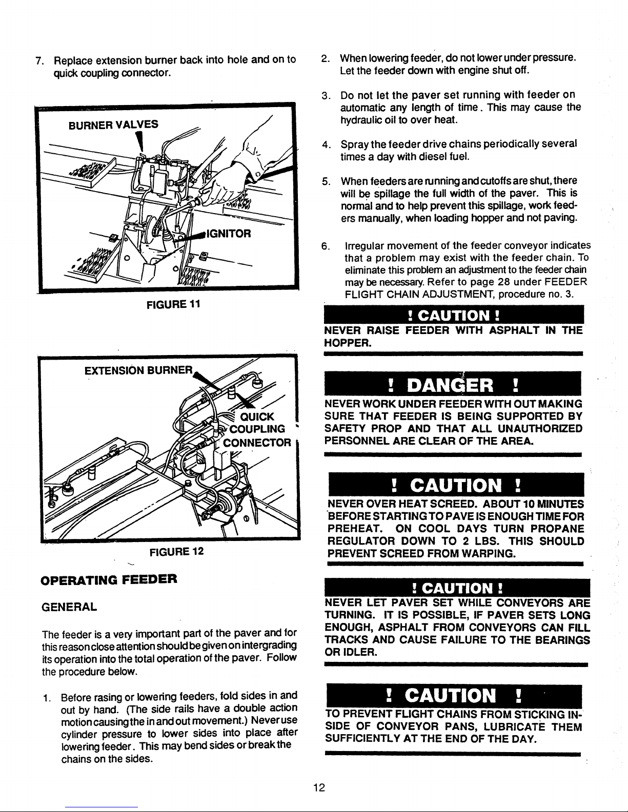
1. Tumoffallburnervalves. See
Figure
11.
. 2.
Tum
mainpropanevalveon andsetregulatorat 15
Ibs. Referto figure 8.
3.
Jghite
burnerwith striker or lighter. Seefigure9.
4. Hold ignitor burner at end of mainburner. To light
main burner
turn
burner valve on. See figure 11.
(NEVERTURNBURNERVALVEON
UNLESS
FLAME
IS PRESENT.)
5. Repeatprocedure in step4 for opposite side.
a.
The extension burners are held in position to the
screed with a quick coupling
connection.
Remove
the
extension burner from quick couplingconnectorand
light. See figure 12.
7. Replace
extension
burner
back
into hole
and
on to
quick
coupling
connector.
FIGURE
11
FIGURE
12
OPERATING
FEEDER
GENERAL
The feeder is a very
important
part of
the
paver
and
for
thisreason close attention
should
begivenon intergrading
its operation into the total operation of
the
paver. Follow
the procedure below.
1. Before rasing or lowering feeders,
fold
sides
in and
out by hand. (The side rails have a
double
action
motioncausing
theinand
out
movement.)
Never
use
cylinder pressure to
lower
sides into
place
after
loweringfeeder. This
may
bend
sidesorbreak
the
chains on the sides.
2. Whenlowering feeder,
do
not
lower
under
pressure.
Let the
feeder
down
with
engine shut off.
3. Do
not
let
the
paver
set
running
with
feeder
on
automatic
any
length of
time.
This may cause the
hydraulic
oiltoover
heat.
4.
Spray
the
feeder
drive
chains
periodically
several
times a
day
with diesel fuel.
5. Whenreedersare
runningand cutoffsare shut, there
will
~
spillage
the
full
width
of the paver. This is
normal
and
to help
prevent
this
spillage,
work
feed-
ers manually,
when
loading hopper
and
not paving.
6. Irregular movement of the feeder conveyor indicates
that a problem
may
exist with
the
feeder chain. To
eliminate this problem an adjustmenttothe feeder
chain
may be necessary.
Refertopage
28 under FEEDER
FLIGHT CHAIN ADJUSTMENT,
procedure no. 3.
!
CAUTION!
NEVER RAISE FEEDER WITH ASPHALT IN·
THE·
HOPPER.
~
!
DAN
,'ER
!
NEVERWORK UNDER FEEDER WITH OUT
MAKING
SURE
THAT
FEEDER IS BEING
SUPPORTED
BY
SAFETY PROP
AND
THAT
ALL
UNAUTHORIZED
PERSONNEL ARE CLEAR OF THE AREA.
!
CAUTION!
NEVER
OVER
HEAT
SCREED.
ABOUT 10 MINUTES
·BEFORE
STARTINGTOPAVEISENOUGH
TIME
FOR
PREHEAT.
ON
COOL
DAYS
TURN
PROPANE
REGULATOR
DOWN TO 2 LBS. THIS SHOULD
PREVENT
SCREED
FROM
WARPING.
!
CAUTION!
NEVER LET PAVER
SET
WHILE CONVEYORS ARE
TURNING. IT IS POSSIBLE, IF PAVER SETS LONG
ENOUGH, ASPHALT FROM
CONVEYORS
CAN
FILL
TRACKS AND CAUSE FAILURE TO THE BEARINGS
OR
IDLER.
!
CAUTION
! .
TO
PREVENT
FLIGHT
CHAINS
FROM
S"TICKING IN-"
SIDE OF CONVEYOR PANS,
LUBRICATE
THEM
SUFFICIENTLYATTHE END OF THE DAY.
12
OPERATION
OF
ELECTRIC
FLIGHT SCREWS
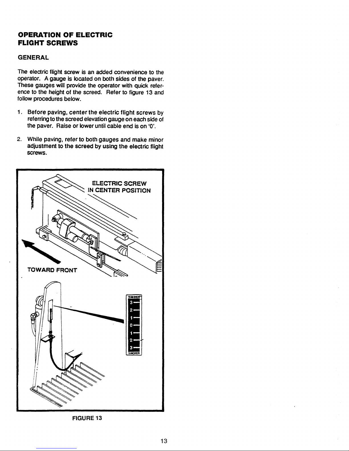
GENERAL
The electric flight screw is an added convenience to the
operator. A gauge is located on both sides of the paver.
These gauges
will provide the
operator
with quick refer-
ence to
the
height of the screed. Refer to figure 13 and
follow procedures below.
1.
Before
paving,
center
the
electric
flight
screws
by
referringto the screed elevation gaugeoneachside of
the paver. Raise or
lower
until
cable
end
is on
cO'.
2. While paving.
refer
to both
gauges
and
make
minor
adjustmenttothe
screedbyusing
the
electric
flight
screws.
ELECTRIC
SCREW
IN
CENTER
POSITION
FIGURE 13
13
OPERATION
OF
HYDRAULIC
CUTOFFS
GENERAL
The cutoffsare
one
of the
most
importantfunctions of the
paver. whenused properly. Cutoffsare
used
primarilyto
control the flow of asphalt to
the
screed. Cutoffs
can
be
used
when
makingnarrow passes, at Ulilbeginning
and
ending of each passorpull. The cutoffs have been
designed to
break
away if accidently
bitS
a man hole
or
ridge.This feature will prevent excessive damage to
cutoff. (Tack underneath will break.)
1.
Moving
the
hydraulic
handle
forward
will
increase
asphaltflow to the screed. Pulling
the
handlebackwill
decrease asphalt flow.
NOTE
Always
work
cutoff
valve
handle
one
at a
time
when
opening
or
closing. If
both
handles are
worked
together,
normallyone will openorclose before
the
other.
2.
Always
pull
valve
handlestoclose.Ifhandle
is
allowed to return to
center
positiononits own, it
may
pass
center
and
causecutoff to drift open once
pressure is lost.
ELECTRIC
SPRAYDOWN
GENERAL
The
spraydownonyour
machineisused
to sprayfuel oil
on
any
part of
the
machine
that
comes
in contact
with
the
asphalt. Build-up of
this
material
will
cause
damage
to
components.
Spray
the
area
often,
the
screed
extension
on
top
and
bottom,
augers
and
hoppers.
14
1.
Unwrap
the
amountofhose
needed
and
tum
spray
down
switch
on.
Pull
wand
handle
and
spray.
2. .
After
spraying
turn
off
spray
down
switch
and
rewrap
hose.
3. IMPORTANT:
When
using
spraydown
consider
the
environment
anddonot
allow
fuel oil to
run
onto
the
ground.
!
CAUTION!
IF SPRAY
DOWN
PUMPISNOT
TURNED
OFF'AFTER
EACH USE,
THE
PUMP
WILL
RUN OVER BY PASS
AND AFTER A PERIOD
OF
TIME WILL BURN UP
MOTOR.
AUTOMATIC
AUGER
GENERAL
Automatic
augers
are
used
when
laying mats
wider
than
standard
paving
width.
When
used
this will
lessen
the
work
loadonthe
operator.
1. To install
the
paddleonthe
screedextension,extend
the screed6
inches
and
mount
paddleon
endgate
as
shown. Install the same
way
on left endgate. See
figure
14A.
2. In order
for
the
paddletowork,
the
electric
cord
leading
from
the paddle switch should be
plugged
into the receptacle box. A receptacle box is located
on each
sideofthe
paver.
After
the
electrical
cords
are plugged in,
switch
the
two
toggle switchesonthe
.
dashtoON
Automatic
and
pull the auger valve
handles to
engage
augers.
3.
IMPORTANT:
After
the
paddle
on
screed
ex-
tension
has
been
mounted
00
NOT
RETRACT
SCREED
FULLY.
DAMAGE
WILL
OCCUR.
!
CAUTION!
WHEN
USING
AUGERS
DO
NOT
TRY
TO
AUGER
MATERIAL
FROM
ONE
SIDE
OF
MACHINE
TO
THE
OTHER
SIDE.
AUGER
COVER
IN
CENTER
BLOCKS
THE
FLOW.
DAMAGE
WILL
RESULTINBEARINGS
AND
COVER.
NOTE
WhenpaVing basic
widthofmachineaugers are
not
required to run.
AUTOMATIC
AUGERS: NEW STYLE
(TIED IN
WITH
CONVEYORS)
Automatic augers are mostly used when paving 9' or
10' . where' augers are capable of running material over
top of endgates, causing extra hand work.
!
CAUTION
!
NEVER RUN AUGERS WHEN PAVING 81WIDE.
NEVER RUN AUGERS IN REVERSE TO PUSH
MATERIAL
FROM LEFT TO RIGHT OR RIGHT TO
LEFT. Center chain guard prohibits material from
croSsing from one side to the other. (Damage will
occur).
HOW TO OPERATE:
1. Pull auger control handles on valve to "on" for
augers to feed extensions.
2 Tum left & right auger toggles on dash "on",
Now the augers will come on and off with the
conveyors.
3. When paving wider widths, and augers do not
provide sufficient asphalt flow, refer to the
following
step that identifies to
the
corresponding
machine.
15
LOADING
AND
UNLOADING
GENERAL
Trailers used to haul the paver should have ample
capacityto carry the weight of the paver. Place the trailer
in a clear, level area for loading
or
unloading.
Work slowly and
carefully
to avoid accidents. Keep the
area clear.
UNLOADING
1. Remove tie down equipment.
2. Start and warm up engine.
3.
Set
throttle at 1/2 operating RPM. Shifttransmission
into
low range. Set steering control
levers
so paver
moves very slowly.
4. Make sure:
A. Screed position - UP
B. Extendable screed - IN
C.
Gates
below
augers
-
CLOSED
(Caution
-
Neverback up with cutoffgates open.)
D.
Speed
range-LOW
(Never
shift
Transmis-
siononincline.)
.
--
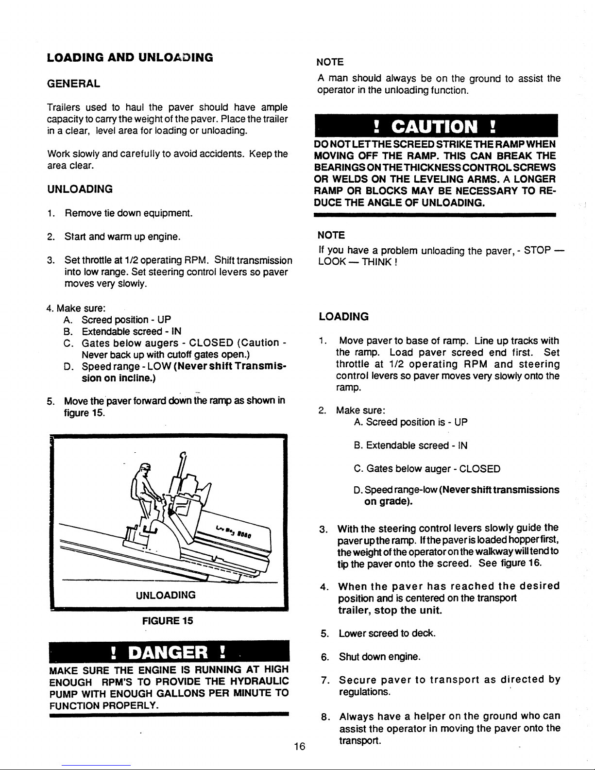
5. Move the 'paverforward down the ramp as shown in
figure
15.
UNLOADING
FIGURE 15
. !
DANGER!
.
MAKE
SURE THE ENGINE IS RUNNING
AT
HIGH
ENOUGH RPM'S TO
PROVIDE
THE
HYDRAULIC
PUMP WITH ENOUGH
GALLONS
PER
MINUTE TO
FUNCTION PROPERLY.
16
NOTE
A man should always be on the
ground
to assist the
operator in the unloading function.
. !
CAUTION!
DO
NOT
LETTHE
SCREED
STRIKE
THE
RAMP
WHEN
MOVING
OFF
THE
RAMP.
THIS
CAN
BREAK
THE
BEARINGSON
THE
THICKNESS
CONTROL
SCREWS
OR
WELDS
ON
THE
LEVELING
ARMS.ALONGER
RAMP
OR
BLOCKS
MAY
BE
NECESSARY
TO RE-
DUCE
THE
ANGLE
OF
UNLOADING.
NOTE
If you have a problem unloading
the
paver,
- STOP -
LOOK-THINK!
LOADING
1. Move
pavertobase
of ramp. Line up tracks
with
the ramp.
Load
paver
screed
end
first.
Set
throttle
at
1/2
operating
RPM
and
steering
control
levers so
paver
moves
very
slowlyonto the
ramp.
2. Make sure:
A. Screed position is - UP
B. Extendable screed - IN
c.Gates
below
auger-CLOSED
D.Speedrange-low(Never
shift
transmissions
on grade).
3.
With
the
steering
control
levers
slowly
guide
the
paverupthe
ramp. If
the
paver is loadedhopperfirst,
the
weightof the operatoron the
walkway
will tend to
tip the
paver0nto
the
screed.
See
figure 16.
4.
When
the
paver
has
reached
the
desired
position and is centered on the transport
trailer,
stop
the
unit.
5.
Lower
screed to deck.
6. Shut
down
engine.
7.
Secure
paver
to
transport
as
directed
by
regulations.
8.
Always
haveahelper
on
the
ground
who
can
assist
the
operatorinmoving
the
paver
onto
the
transport.
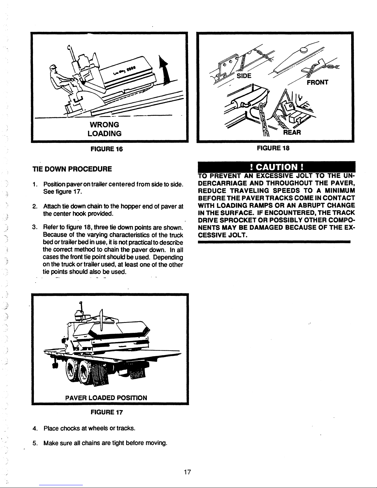
FRONT
WRONG
LOADING
FIGURE 16
FIGURE 18
TIE
DOWN
PROCEDURE
1. Position paverontrailer centered from sidetoside.
Seefigure 17.
2. Attachtie down chainto the hopper endof paver at
thecenter hook provided.
3. Referto figure 18,three tiedown pointsare
shown.
Becauseof the varying characteristics of the truck
bedortrailerbedin use,itisnotpracticalto describe
the correct methodto chainthe paver down. In all
casesthe fronttie
point shouldbe used. Depending
onthetruck or trailer used,at least oneof the other
tie pointsshould also
be used.
!
CAUTION!
TO PREVENT AN EXCESSIVE
JOLT
TO THE UN-
DERCARRIAGE AND
THROUGHOUT
THE
PAVER,
REDUCE
TRAVELING
SPEEDS
TO A MINIMUM
BEFORE
THE
PAVER
TRACKS
COME
IN CONTACT
WITH
LOADING
RAMPS OR AN ABRUPT CHANGE
IN THE SURFACE. IF ENCOUNTERED, THE TRACK
DRIVE
SPROCKET
OR
POSSIBLY
OTHER
COMPO-
NENTS
MAY
BE DAMAGED BECAUSE OF THE EX-
CESSIVE
JOLT.
PAVER LOADED POSITION
FIGURE 17
4.
Place
chocksat wheelsor tracks.
5. Makesure all chains aretight before moving.
17
PAVER PREPARATION INSTRUCTIONS
Topreventcostlydowntime,the pavershouldbechecked
thoroughlybefore eachuse. Use
the
list belowto assist
in checking the paver.
1. Check engine
oil
(see enginemanual), hydraulicoil,
gear
box oil
and
diesel fuel.
2.
Referto
LubricationCharton
page
25and lubricate
as specified. (Somearea
orweather
conditions may
require extra lubrication).
3. Checkhydraulic
hoses,
fittings, pumpsand motors for
leaks, excessive wear
or
damage.
4. Checkthe engine
safety
switch: (the
engine
should
only
start
when
forward/reverse
levers
are
in the
neutral position.) See figure 2.
5.
Checkallelectricalfunctionsbefo~edistributingasphalt.
6. Sprayfuel oil on any part of
the
paver
thatcomes in
contact with asphalt.
7. Check burner ignition.
STARTING TO PAVE
GENERAL
The paveris capable of placing bituminous base, binder
and surface courses, lime
or
portland cement stabilized
sub-base and gradedaggregate materials up to a thickness of 6 inches. The paverhas aproductionrate of 250
tons
per
hour.
Equipped with electric and manual thickness controls
and a 8' to 13' wide screed,
the
paver
can
handle everythingfromdrivewaysand smallparking lots
to large parking areas and secondary roads.
Before starting to pave,
keep
the
following points in
mind:
A. Planthe project so
that
the
narrowest
passes
are
first, (the basicwidthof the paver) leaving
the
widest
pass until last.
B.
Make
sure to
useareference
guideline.
This
can
be a curb, gutter, adjacent mat
or
a string line. It is
importantthat the first pass
be straight as it will be
the
guideline
for
the following passes.
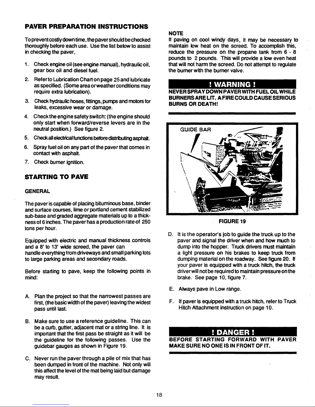
Use
the
guidebar gauges as shown in Figure 19.
C.
Never
run
the
paver
through
a pile of
mix
that
has
been dumped in front of the machine. Not
only
will
thisaffect the level of
the
mat beinglaid but damage
may result.
18
NOTE
If paving on
cool
windy days, it may be necessary to
maintain low heat
on
the
screed. To accomplish this,
reduce
the
pressure
on
the propane tank from 6 - 8
pounds to 2 pounds.
This
will provide a low even heat
that
will not
harm
the
screed. Do not attempt to regUlate
the
bumer
with
the
burner
valve.
!
WARNING!
NEVER
SPRAY
DOWN
PAVERWITH FUEL
OIL
WH"ILE
BURNERSARE
LIT.
AFIRECOULD CAUSESERIOUS
BURNS OR DEATH!
. FIGURE
19
D. It is
the
operator's
jobtoguide
the
truckupto
the
paver and signal
the
driver
when
and
how
much to
dump
into
the
hopper. Truck drivers roost maintain
a light pressure on his brakes to keep
truck
from
dumping material
on
the roadway. See figure 20. If
your
paver is equipped with a
truck
hitch, the truck·
driverwill
not
be requiredto maintainpressureon the
brake. See page 10, figure 7.
E. Always pave in
Low
range.
F. If paver is equipped with a truck hitch, referto Truck
Hitch Attachment instruction on page 10.
!
DANGER!
BEFORE
STARTING
FORWARD
WITH
PAVER
MAKE
SURE
NO
ONE
IS IN FRONTOF
IT.
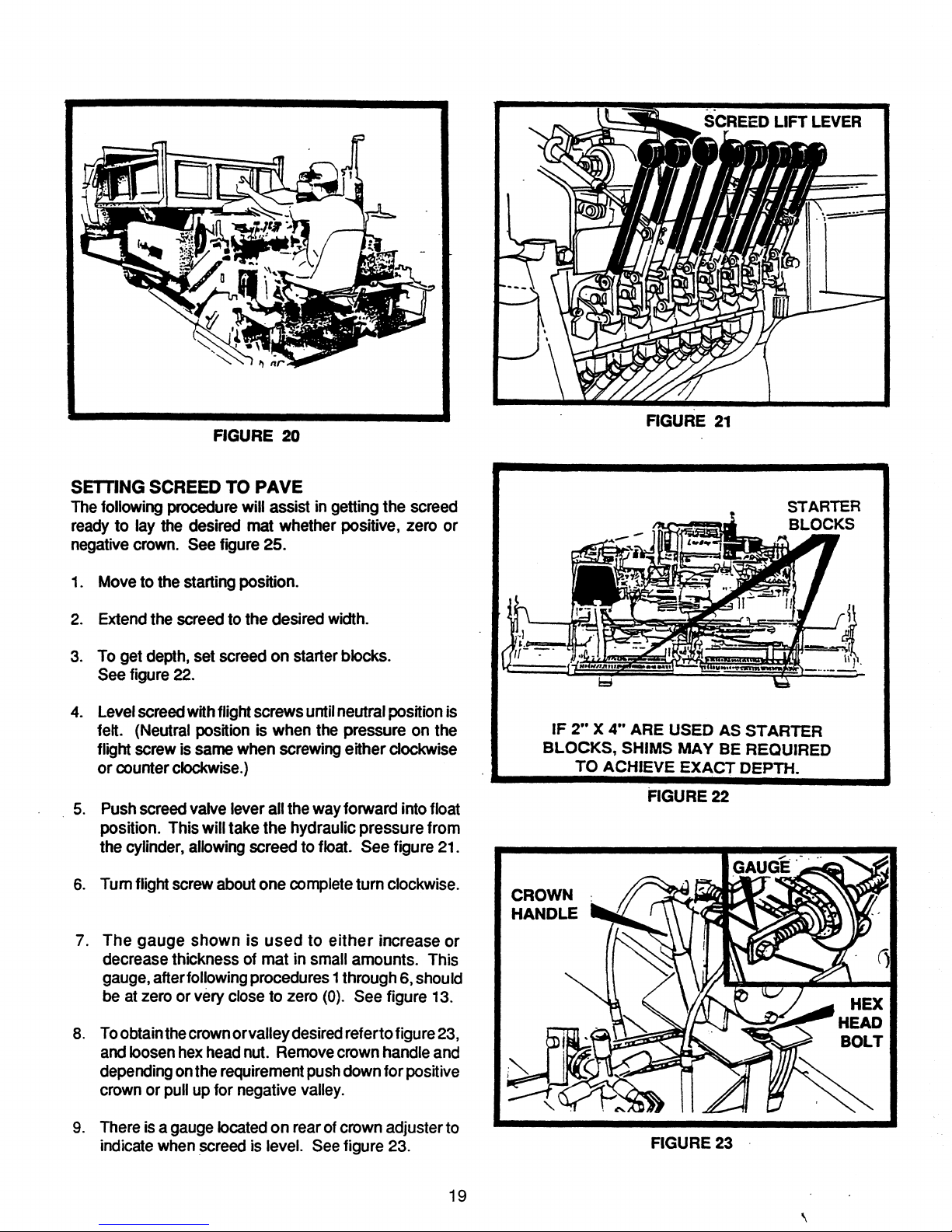
FIGURE 20
SETTING SCREED TO
PAVE
Thefollowing procedurewill assist in getting the screed
ready
to lay the desired mat whether positive, zero or
negative crown. See figure
25.
1. Moveto the startingposition.
2. Extendthe screedto the desiredwidth.
3. To get depth,set screedon starterblocks.
Seefigure 22.
4. Levelscreedwith flightscrews untilneutral positionis
felt. (Neutral position is when the pressure on the
flight screwis samewhen screwingeither clockwise
or counterclockwise.)
5. Pushscreedvalve leverallthewayforward intofloat
position. Thiswilltakethe hydraulic pressurefrom
the cylinder,allowingscreedto float. See figure 21.
6. Tumflightscrewaboutone completeturn clockwise.
7. The gauge shown is used to either increase or
decreasethickness of mat in small amounts. This
gauge,afterfollowingprocedures1through6, should
be at zeroor
veryclose to zero (0). Seefigure 13.
8. Toobtainthecrownorvalley desiredreferto figure23,
andloosenhexheadnut. Removecrownhandleand
dependingonthe requirement pushdownforpositive
crownor pull upfor negativevalley.
9. Thereis agaugelocatedon rearofcrownadjusterto
indicatewhenscreedis level. Seefigure 23.
19
FIGURE 21
IF2"X4"ARE USED AS STARTER
BLOCKS,
SHIMS
MAY
BE REQUIRED
TO
ACHIEVE
EXACT
DEPTH.
FIGURE 22
CROWN
HANDLE
FIGURE23
.
,

10. Setcrown
control.
The screed plate is a one-piece
unit which is
adually
bentto provide the required
crown setting. See figures
24 and 25.
12. Tighten hex head nut on vibratorsecurely before
paving.
MAXIMUM CROWN
2"
FIGURE24
11. To get exactcrownorvalley, measure
the
distance
betWeen a flat level surface to the centerbottom
portion of screed.
See
figure 24. Make adjUst-
mentswith crown and valley control.
posinVE
ZERO
NEGATIVE
FIGURE 25
NOTE
Positive
crowniswhen
the
middleofthe
mat
is raised
to
permit
watertodraintoeach
side.
Negative
crown
is the
loweringofthe
centerofthe
screed plate. Negative crown might be used in an
alley
where
drainage
down
the
center
of the alley is
necessary.
20
Crown
may
be placed in
the
leading edge
and/or
the
trailing
edgeofthe
screed
plate.
Crowninthe
leading
edge aids material
flow
under
the
screed plate, only.
Trailing
edge
crown
puts
a crown in the mat. As an
example; trailing edge
crown
is 9, leading
edge
crown
is 1/8". With this
set-up
there
will
not be
any
crown
placed in
the
mat
laid by
the
paver, however, material
flow under
the
screed
plate
will be improved..Trailing
edge crown is
set
at 0
when
shipped from
the
factory.
The chain connecting
the
leading and trailing edge
crowncontrol assures
that
the
relationshipof
the
edges
remains
constant as the trailing edge is
changed
to
meet job conditions.
SETTING SCREED ENDGATES
1. Onfirstpass
unlock
depth
screws
and
lower
endgateto
about1/4"off desired depth.
This
should providea
nice square edge.
See
figure 26.
2.
The scale located on
each
endgatewill
show
proper
setting
or
depth.
3.
Tilt
adjustersonendgate
aretobe
setsofront
of
endgate tilts down slightly
when
screed is lifted.
4. This will allowthe endgateto set itself to grade.
NOTE: When paving never let end gate carry
the
weight
of the screed. Thiswill
cause
screed compactionto vary
and slickness.
5. During
operationifendgates
starttodig
in at front,
adjust the tilt so the endgate tilts back.
 Loading...