

Page 1
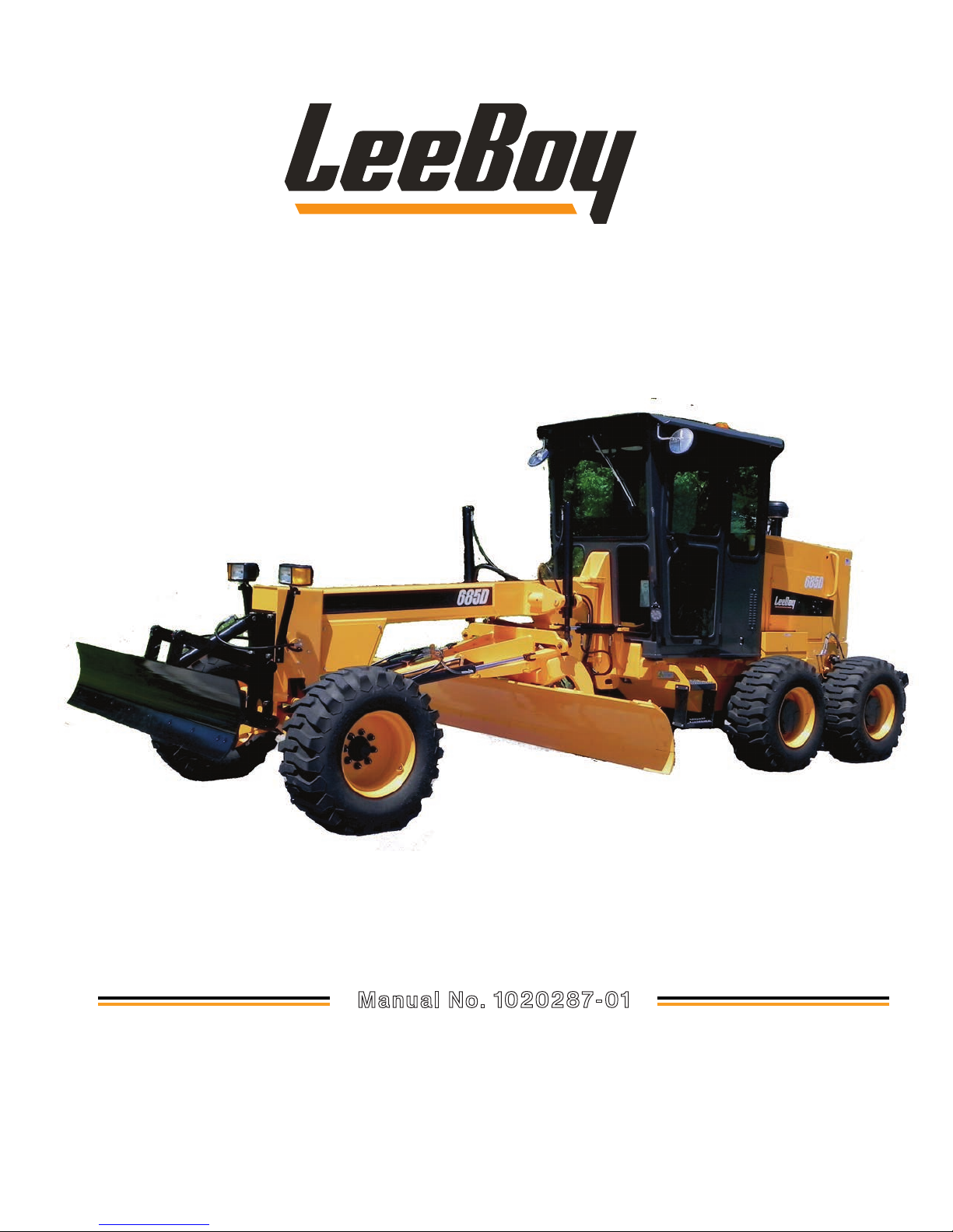
Operations, Service, and Parts Manual
LEEBOY 685D MOTOR GRADER
Manual No. 1020287-01
This manual applies to
Serial Number 183712
and above.
Page 2

Page 3
Thumb Index
Safety
Information and Specifications
Component Location
Operation
1
2
3
4
Maintenance
Schematics
Illustrated Parts List (IPL)
5
6
7
Page 4

Legal Notices
iv
LeeBoy 685D Motor Grader
Page 5

TABLE OF CONTENTS
Page
Safety . . . . . . . . . . . . . . . . . . . . . . . . . . . . . . . . . . . . 1-1
Safety Precautions . . . . . . . . . . . . . . . . . . . . . . . . . . . . . 1-4
Machine Precautions . . . . . . . . . . . . . . . . . . . . . . . . . . . . 1-7
Hot Material Precautions . . . . . . . . . . . . . . . . . . . . . . . 1-7
Hydraulic Systems Precautions . . . . . . . . . . . . . . . . . . . 1-7
Refueling Precautions . . . . . . . . . . . . . . . . . . . . . . . . 1-8
Battery Precautions . . . . . . . . . . . . . . . . . . . . . . . . . 1-8
Starting and Stopping Precautions . . . . . . . . . . . . . . . . . . 1-8
Parking Precautions . . . . . . . . . . . . . . . . . . . . . . . . . 1-8
Operating Precautions . . . . . . . . . . . . . . . . . . . . . . . . 1-8
Poor Visibility . . . . . . . . . . . . . . . . . . . . . . . . . . . . 1-9
Snow Removal . . . . . . . . . . . . . . . . . . . . . . . . . . . . 1-9
Storage Precautions . . . . . . . . . . . . . . . . . . . . . . . . . 1-9
Maintenance Precautions . . . . . . . . . . . . . . . . . . . . . . 1-9
Tire Precautions . . . . . . . . . . . . . . . . . . . . . . . . . . . 1-10
Safety Decals . . . . . . . . . . . . . . . . . . . . . . . . . . . . . . . 1-11
Safety Decals Care . . . . . . . . . . . . . . . . . . . . . . . . . 1-12
Decal Installation (Sticker Type) . . . . . . . . . . . . . . . . . . . 1-12
Decal Installation (Top Protected) . . . . . . . . . . . . . . . . . . 1-12
Cab Option Safety Decals . . . . . . . . . . . . . . . . . . . . . . 1-12
Information and Specications . . . . . . . . . . . . . . . . . . . . . . . . 2-1
One Year Limited Warranty . . . . . . . . . . . . . . . . . . . . . . . . . 2-2
Contact Information . . . . . . . . . . . . . . . . . . . . . . . . . . . . 2-3
Specication Charts . . . . . . . . . . . . . . . . . . . . . . . . . . . . 2-4
Torque Specications . . . . . . . . . . . . . . . . . . . . . . . . . . . 2-7
Standard Inch Fasteners . . . . . . . . . . . . . . . . . . . . . . . 2-7
Metric Fasteners . . . . . . . . . . . . . . . . . . . . . . . . . . . 2-8
Hydraulic Fittings . . . . . . . . . . . . . . . . . . . . . . . . . . 2-8
Determining Proper Torque . . . . . . . . . . . . . . . . . . . . . 2-9
LeeBoy 685D Motor Grader v
Page 6

Table of Contents
Component Location . . . . . . . . . . . . . . . . . . . . . . . . . . . . . 3-1
Components Overview . . . . . . . . . . . . . . . . . . . . . . . . . . . 3-3
Operator Station . . . . . . . . . . . . . . . . . . . . . . . . . . . 3-3
Engine . . . . . . . . . . . . . . . . . . . . . . . . . . . . . . . . 3-3
Hydrostatic Drive . . . . . . . . . . . . . . . . . . . . . . . . . . 3-4
Electrical System . . . . . . . . . . . . . . . . . . . . . . . . . . 3-4
Scarier (Optional) . . . . . . . . . . . . . . . . . . . . . . . . . . 3-5
Standard Equipment/Options . . . . . . . . . . . . . . . . . . . . 3-5
Machine Overview . . . . . . . . . . . . . . . . . . . . . . . . . . . . . 3-6
Operator Station . . . . . . . . . . . . . . . . . . . . . . . . . . . . . . 3-7
Steering Column Controls . . . . . . . . . . . . . . . . . . . . . . . . . 3-8
Main Control Panel . . . . . . . . . . . . . . . . . . . . . . . . . . . . . 3-10
Heat and Air Conditioning (Cab Option) . . . . . . . . . . . . . . . . . . . 3-12
Operation . . . . . . . . . . . . . . . . . . . . . . . . . . . . . . . . . . 4-1
General Information . . . . . . . . . . . . . . . . . . . . . . . . . . . . 4-3
Receiving the Machine . . . . . . . . . . . . . . . . . . . . . . . . 4-3
Initial and Daily Inspection . . . . . . . . . . . . . . . . . . . . . . 4-3
Start-Up Procedure . . . . . . . . . . . . . . . . . . . . . . . . . . . . 4-4
Brake Check . . . . . . . . . . . . . . . . . . . . . . . . . . . . 4-4
Starting the Engine . . . . . . . . . . . . . . . . . . . . . . . . . . 4-4
Cold Weather Starting . . . . . . . . . . . . . . . . . . . . . . . . 4-5
Stopping the Engine . . . . . . . . . . . . . . . . . . . . . . . . . 4-5
Emergency Stop Button . . . . . . . . . . . . . . . . . . . . . . . 4-5
Regeneration (REGEN) . . . . . . . . . . . . . . . . . . . . . . . . . . . 4-6
Diesel Exhaust Fluid (DEF) After-Treatment System . . . . . . . . . 4-6
PV485 Digital Display . . . . . . . . . . . . . . . . . . . . . . . . . . . 4-7
Gauge Screen . . . . . . . . . . . . . . . . . . . . . . . . . . . . 4-8
Main Menu Screen . . . . . . . . . . . . . . . . . . . . . . . . . . 4-10
Diagnostics . . . . . . . . . . . . . . . . . . . . . . . . . . . . . 4-11
System Info . . . . . . . . . . . . . . . . . . . . . . . . . . . . .4-12
User Settings . . . . . . . . . . . . . . . . . . . . . . . . . . . .4-12
Tier 4F . . . . . . . . . . . . . . . . . . . . . . . . . . . . . . . . 4-14
Regen Request . . . . . . . . . . . . . . . . . . . . . . . . . . . 4-15
Driving the Grader . . . . . . . . . . . . . . . . . . . . . . . . . . . . . 4-16
Regen Inhibit . . . . . . . . . . . . . . . . . . . . . . . . . . . . . 4-16
Adjust Seat . . . . . . . . . . . . . . . . . . . . . . . . . . . . . 4-17
Adjust Steering Console . . . . . . . . . . . . . . . . . . . . . . . 4-18
vi
LeeBoy 685D Motor Grader
Page 7

Table of Contents
2-Speed High/Low . . . . . . . . . . . . . . . . . . . . . . . . . . 4-18
Axle Travel/Work . . . . . . . . . . . . . . . . . . . . . . . . . . . 4-18
Throttle . . . . . . . . . . . . . . . . . . . . . . . . . . . . . . .4-18
Directional Control . . . . . . . . . . . . . . . . . . . . . . . . . . 4-19
Braking . . . . . . . . . . . . . . . . . . . . . . . . . . . . . . .4-19
Steering . . . . . . . . . . . . . . . . . . . . . . . . . . . . . . . 4-20
Articulation . . . . . . . . . . . . . . . . . . . . . . . . . . . . . . 4-20
Front Wheel Lean . . . . . . . . . . . . . . . . . . . . . . . . . . 4-21
Motor Grader Terms . . . . . . . . . . . . . . . . . . . . . . . . . . . . 4-22
Moldboard . . . . . . . . . . . . . . . . . . . . . . . . . . . . . . . . . 4-23
Circle Turn Cushion Valve . . . . . . . . . . . . . . . . . . . . . . 4-24
Grader Attachments . . . . . . . . . . . . . . . . . . . . . . . . . . . . 4-25
Mounting Front Attachments . . . . . . . . . . . . . . . . . . . . . 4-25
Operating Front Attachments . . . . . . . . . . . . . . . . . . . .4-26
Front Blade Float. . . . . . . . . . . . . . . . . . . . . . . . . . . 4-26
Scariers . . . . . . . . . . . . . . . . . . . . . . . . . . . . . .4-27
Operating a Scarier . . . . . . . . . . . . . . . . . . . . . . . . . 4-28
Replacing Scarier Teeth . . . . . . . . . . . . . . . . . . . . . .4-28
Operating Techniques . . . . . . . . . . . . . . . . . . . . . . . . . . . 4-29
Grading Tips . . . . . . . . . . . . . . . . . . . . . . . . . . . . . 4-29
Grading Around Objects . . . . . . . . . . . . . . . . . . . . . . . 4-30
Spreading and Leveling . . . . . . . . . . . . . . . . . . . . . . . 4-31
Slope Work . . . . . . . . . . . . . . . . . . . . . . . . . . . . . 4-32
Grading an “S” Curve Shoulder . . . . . . . . . . . . . . . . . . . .4-33
Road Maintenance . . . . . . . . . . . . . . . . . . . . . . . . . . . . . 4-33
Gravel and Dirt Roads . . . . . . . . . . . . . . . . . . . . . . . . 4-34
Crowning the Road . . . . . . . . . . . . . . . . . . . . . . . . .4-35
Ditch Work . . . . . . . . . . . . . . . . . . . . . . . . . . . . . . 4-35
Cul-De-Sacs . . . . . . . . . . . . . . . . . . . . . . . . . . . . . 4-36
Transport . . . . . . . . . . . . . . . . . . . . . . . . . . . . . . . . .4-37
Loading . . . . . . . . . . . . . . . . . . . . . . . . . . . . . . . 4-37
Unloading . . . . . . . . . . . . . . . . . . . . . . . . . . . . . . 4-38
Tie-Down Procedure . . . . . . . . . . . . . . . . . . . . . . . . . 4-38
Towing . . . . . . . . . . . . . . . . . . . . . . . . . . . . . . . . . . . 4-38
Options . . . . . . . . . . . . . . . . . . . . . . . . . . . . . . . . . .4-39
Cab Option . . . . . . . . . . . . . . . . . . . . . . . . . . . . .4-39
Sliding Moldboard . . . . . . . . . . . . . . . . . . . . . . . . . . 4-40
LeeBoy 685D Motor Grader
vii
Page 8

Table of Contents
Circle Side Shift . . . . . . . . . . . . . . . . . . . . . . . . . . . 4-40
Secondary Steering . . . . . . . . . . . . . . . . . . . . . . . . . 4-40
All-Wheel Drive (AWD) . . . . . . . . . . . . . . . . . . . . . . . . 4-41
Cold Weather Engine Package . . . . . . . . . . . . . . . . . . . . 4-41
Reverse Camera System . . . . . . . . . . . . . . . . . . . . . . . 4-41
Maintenance . . . . . . . . . . . . . . . . . . . . . . . . . . . . . . . . . 5-1
Maintenance Schedule . . . . . . . . . . . . . . . . . . . . . . . . . . . 5-3
Maintenance Schedule . . . . . . . . . . . . . . . . . . . . . . . . . . . 5-4
Prepare for Maintenance . . . . . . . . . . . . . . . . . . . . . . . 5-4
10-Hour or Daily Routine Maintenance . . . . . . . . . . . . . . . . 5-4
50-Hour Routine Maintenance . . . . . . . . . . . . . . . . . . . . 5-4
100-Hour or Monthly Routine Maintenance . . . . . . . . . . . . . . 5-5
250-Hour or Quarterly Routine Maintenance . . . . . . . . . . . . . 5-5
500-Hour or Semi-Annual Routine Maintenance . . . . . . . . . . . 5-5
1000-Hour or Annual Routine Maintenance . . . . . . . . . . . . . . 5-5
2000-Hour or Every Two Years Maintenance . . . . . . . . . . . . 5-5
3000-Hour or Every Three Years Maintenance . . . . . . . . . . . . 5-5
Lubrication . . . . . . . . . . . . . . . . . . . . . . . . . . . . . . . . . 5-6
Grease Points . . . . . . . . . . . . . . . . . . . . . . . . . . . . 5-6
Axle Lubricants . . . . . . . . . . . . . . . . . . . . . . . . . . . 5-8
Breathers . . . . . . . . . . . . . . . . . . . . . . . . . . . . . . 5-8
Planetary Hubs . . . . . . . . . . . . . . . . . . . . . . . . . . .5-10
Machine Adjustments . . . . . . . . . . . . . . . . . . . . . . . . . . .5-10
Moldboard Blade . . . . . . . . . . . . . . . . . . . . . . . . . .5-10
Drawbar Ball and Socket . . . . . . . . . . . . . . . . . . . . . . . 5-11
Toe-In . . . . . . . . . . . . . . . . . . . . . . . . . . . . . . . . 5-12
Park Brake (Rear Bogie Axle) . . . . . . . . . . . . . . . . . . . .5-12
Engine Maintenance . . . . . . . . . . . . . . . . . . . . . . . . . . . . 5-13
Check Engine Oil . . . . . . . . . . . . . . . . . . . . . . . . . .5-13
Change Engine Oil and Filter . . . . . . . . . . . . . . . . . . . . . 5-13
Engine Drive Belt . . . . . . . . . . . . . . . . . . . . . . . . . .5-14
Air Filter . . . . . . . . . . . . . . . . . . . . . . . . . . . . . . . 5-15
Radiator Coolant . . . . . . . . . . . . . . . . . . . . . . . . . . . 5-15
Selective Catalytic Reduction (SCR) System . . . . . . . . . . . . . 5-16
DEF Tank Filter . . . . . . . . . . . . . . . . . . . . . . . . . . .5-18
DEF Dosing Unit Filter . . . . . . . . . . . . . . . . . . . . . . . . 5-19
viii
LeeBoy 685D Motor Grader
Page 9

Table of Contents
Fuel System . . . . . . . . . . . . . . . . . . . . . . . . . . . . . . . . 5-19
Fuel Filter . . . . . . . . . . . . . . . . . . . . . . . . . . . . . . 5-20
Fuel Water Separator . . . . . . . . . . . . . . . . . . . . . . . .5-20
Electrical System . . . . . . . . . . . . . . . . . . . . . . . . . . . . . . 5-21
Battery Servicing . . . . . . . . . . . . . . . . . . . . . . . . . . . 5-21
Alternator Servicing . . . . . . . . . . . . . . . . . . . . . . . . . 5-22
Fuse Boxes . . . . . . . . . . . . . . . . . . . . . . . . . . . . . 5-22
Lighting . . . . . . . . . . . . . . . . . . . . . . . . . . . . . . . 5-23
Dielectric Grease . . . . . . . . . . . . . . . . . . . . . . . . . .5-24
Hydraulic System . . . . . . . . . . . . . . . . . . . . . . . . . . . . .5-25
Checking Hydraulic Oil Level . . . . . . . . . . . . . . . . . . . .5-25
Change Hydraulic Oil and Filter . . . . . . . . . . . . . . . . . . .5-26
Change Hydraulic Oil Cap Strainer . . . . . . . . . . . . . . . . . . 5-27
Hydraulic Pump and Motor . . . . . . . . . . . . . . . . . . . . . . 5-27
Hydraulic Test Ports . . . . . . . . . . . . . . . . . . . . . . . . . 5-28
Chassis . . . . . . . . . . . . . . . . . . . . . . . . . . . . . . . . . . 5-29
Tires . . . . . . . . . . . . . . . . . . . . . . . . . . . . . . . . 5-29
Repack Front Wheel Bearings . . . . . . . . . . . . . . . . . . . . 5-30
Replacement Procedures . . . . . . . . . . . . . . . . . . . . . . . . . 5-31
Batteries . . . . . . . . . . . . . . . . . . . . . . . . . . . . . . . 5-31
Radiator Hoses . . . . . . . . . . . . . . . . . . . . . . . . . . . 5-32
Moldboard Blade . . . . . . . . . . . . . . . . . . . . . . . . . .5-33
Side-Cut Edges . . . . . . . . . . . . . . . . . . . . . . . . . . . 5-33
Moldboard Slide Cylinder . . . . . . . . . . . . . . . . . . . . . .5-34
Moldboard Lift Cylinders . . . . . . . . . . . . . . . . . . . . . . . 5-35
Moldboard Tilt Cylinders . . . . . . . . . . . . . . . . . . . . . . . 5-36
Moldboard Angle Cylinder . . . . . . . . . . . . . . . . . . . . . . 5-37
Articulate Cylinders . . . . . . . . . . . . . . . . . . . . . . . . .5-37
Wheel Steering Cylinder . . . . . . . . . . . . . . . . . . . . . . . 5-38
Wheel Lean Cylinder . . . . . . . . . . . . . . . . . . . . . . . . .5-39
Scarier Lift Cylinder . . . . . . . . . . . . . . . . . . . . . . . . . 5-39
Welding on Machine . . . . . . . . . . . . . . . . . . . . . . . . . . . . 5-40
Front Blade Lift Cylinder (Option) . . . . . . . . . . . . . . . . . . . 5-40
Winterizing for Storage . . . . . . . . . . . . . . . . . . . . . . . . . . . 5-41
Periodic Maintenance in Storage . . . . . . . . . . . . . . . . . . . 5-42
Removing from Storage . . . . . . . . . . . . . . . . . . . . . . . 5-42
Hydraulic Motor Start-Up . . . . . . . . . . . . . . . . . . . . . . . 5-43
LeeBoy 685D Motor Grader
ix
Page 10

Table of Contents
Troubleshooting Chart . . . . . . . . . . . . . . . . . . . . . . . . . . . 5-44
PV485 Diagnostic Trouble Code (DTC) Chart . . . . . . . . . . . . . . . . 5-51
PV485 Troubleshooting . . . . . . . . . . . . . . . . . . . . . . . 5-56
Schematics . . . . . . . . . . . . . . . . . . . . . . . . . . . . . . . . . 6-1
Electrical Schematic (1 of 9) . . . . . . . . . . . . . . . . . . . . . . . . 6-3
Electrical Schematic (2 of 9) . . . . . . . . . . . . . . . . . . . . . . . . 6-5
Electrical Schematic (3 of 9) . . . . . . . . . . . . . . . . . . . . . . . . 6-7
Electrical Schematic (4 of 9) . . . . . . . . . . . . . . . . . . . . . . . . 6-9
Electrical Schematic (5 of 9) . . . . . . . . . . . . . . . . . . . . . . . . 6-11
Electrical Schematic (6 of 9) . . . . . . . . . . . . . . . . . . . . . . . . 6-13
Electrical Schematic (7 of 9) . . . . . . . . . . . . . . . . . . . . . . . . 6-15
Electrical Schematic (8 of 9) . . . . . . . . . . . . . . . . . . . . . . . . 6-17
Electrical Schematic (9 of 9) . . . . . . . . . . . . . . . . . . . . . . . . 6-19
Rear Harness (1 of 2) . . . . . . . . . . . . . . . . . . . . . . . . . . . . 6-21
Rear Harness (2 of 2) . . . . . . . . . . . . . . . . . . . . . . . . . . . . 6-23
Front Harness (1 of 2) . . . . . . . . . . . . . . . . . . . . . . . . . . . . 6-25
Front Harness (2 of 2) . . . . . . . . . . . . . . . . . . . . . . . . . . .6-27
Cab Harness (1 of 2) . . . . . . . . . . . . . . . . . . . . . . . . . . . . 6-29
Cab Harness (2 of 2) . . . . . . . . . . . . . . . . . . . . . . . . . . . . 6-31
Engine Harness (1 of 2) . . . . . . . . . . . . . . . . . . . . . . . . . . . 6-33
Engine Harness (2 of 2) . . . . . . . . . . . . . . . . . . . . . . . . . .6-35
Steering Console Harness (1 of 2) . . . . . . . . . . . . . . . . . . . . .6-37
Steering Console Harness (2 of 2) . . . . . . . . . . . . . . . . . . . . . 6-39
Control Panel (1 of 5) . . . . . . . . . . . . . . . . . . . . . . . . . . . . 6-41
Control Panel (2 of 5) . . . . . . . . . . . . . . . . . . . . . . . . . . . . 6-43
Control Panel (3 of 5) . . . . . . . . . . . . . . . . . . . . . . . . . . . . 6-45
Control Panel (4 of 5) . . . . . . . . . . . . . . . . . . . . . . . . . . . . 6-47
Control Panel (5 of 5) . . . . . . . . . . . . . . . . . . . . . . . . . . . . 6-49
Hydraulic Schematic (1 of 5) . . . . . . . . . . . . . . . . . . . . . . . .6-51
Hydraulic Schematic (2 of 5) . . . . . . . . . . . . . . . . . . . . . . . . 6-53
Hydraulic Schematic (3 of 5) . . . . . . . . . . . . . . . . . . . . . . . . 6-55
Hydraulic Schematic (4 of 5) . . . . . . . . . . . . . . . . . . . . . . . . 6-57
Hydraulic Schematic (5 of 5) . . . . . . . . . . . . . . . . . . . . . . . . 6-59
Illustrated Parts List . . . . . . . . . . . . . . . . . . . . . . . . . . . . . 7-1
Quick Reference . . . . . . . . . . . . . . . . . . . . . . . . . . . . . 7-3
Boom Articulation . . . . . . . . . . . . . . . . . . . . . . . . . . . . . 7-4
x
LeeBoy 685D Motor Grader
Page 11

Table of Contents
Boom Pivot . . . . . . . . . . . . . . . . . . . . . . . . . . . . . . . . . 7-6
Rear Drive Assembly . . . . . . . . . . . . . . . . . . . . . . . . . . . . 7-8
Front Axle Assembly, 2WD (1 of 3) . . . . . . . . . . . . . . . . . . . . .7-10
Front Axle Assembly, 2WD (2 of 3) . . . . . . . . . . . . . . . . . . . . . 7-12
Front Axle Assembly, 2WD (3 of 3) . . . . . . . . . . . . . . . . . . . . . 7-14
OPTION-Front Axle Assembly, AWD (1 of 3) . . . . . . . . . . . . . . . . . 7-16
OPTION-Front Axle Assembly, AWD (2 of 3) . . . . . . . . . . . . . . . . 7-18
OPTION-Front Axle Assembly, AWD (3 of 3) . . . . . . . . . . . . . . . .7-20
MoldboardTurntable Assembly, 11 Ft/12 Ft (1 of 4) . . . . . . . . . . . . . . 7-22
Moldboard Turntable Assembly, 11 Ft/12 Ft (2 of 4). . . . . . . . . . . . . . 7-24
Moldboard Turntable Assembly, 11 Ft/12 Ft (3 of 4) . . . . . . . . . . . . .7-26
Moldboard Turntable Assembly, 11 Ft/12 Ft (4 of 4) . . . . . . . . . . . . .7-28
Canopy Assembly . . . . . . . . . . . . . . . . . . . . . . . . . . . . . 7-30
Cab Assembly - Exterior (1 of 2) . . . . . . . . . . . . . . . . . . . . . . . 7-32
Cab Assembly - Exterior (2 of 2) . . . . . . . . . . . . . . . . . . . . . .7-34
Cab Assembly - Interior . . . . . . . . . . . . . . . . . . . . . . . . . .7-36
Cab Assembly - AIr Conditioning (1 of 2) . . . . . . . . . . . . . . . . . . . 7-38
Cab Assembly - AIr Conditioning (2 of 2) . . . . . . . . . . . . . . . . . .7-40
Canopy/Cab Details - Seat . . . . . . . . . . . . . . . . . . . . . . . . . 7-42
Canopy/Cab Details - Interior . . . . . . . . . . . . . . . . . . . . . . . . 7-44
Controls - 10 Station (1 of 3) . . . . . . . . . . . . . . . . . . . . . . . .7-46
Controls - 10 Station (2 of 3) . . . . . . . . . . . . . . . . . . . . . . . . 7-48
Controls - 10 Station (3 of 3) . . . . . . . . . . . . . . . . . . . . . . . . 7-50
Controls - Panel . . . . . . . . . . . . . . . . . . . . . . . . . . . . . . 7-52
Controls - Foot . . . . . . . . . . . . . . . . . . . . . . . . . . . . . . . 7-54
Hydraulics - Tanks . . . . . . . . . . . . . . . . . . . . . . . . . . . . . 7-56
Hydraulics - Tanks (Cont.) . . . . . . . . . . . . . . . . . . . . . . . . .7-58
Hydraulics - 2WD . . . . . . . . . . . . . . . . . . . . . . . . . . . . . . 7-60
Hydraulics - Brake, 2WD/AWD . . . . . . . . . . . . . . . . . . . . . . . 7-62
Hydraulics - Valve Bank, 2WD/AWD . . . . . . . . . . . . . . . . . . . . . 7-64
Hydraulics - Pumps, 2WD . . . . . . . . . . . . . . . . . . . . . . . . .7-66
Hydraulics - Pumps, AWD . . . . . . . . . . . . . . . . . . . . . . . . .7-68
Hydraulics - Pumps, AWD (Cont.) . . . . . . . . . . . . . . . . . . . . . . 7-70
Engine - Shroud . . . . . . . . . . . . . . . . . . . . . . . . . . . . . . 7-72
Engine - Radiator . . . . . . . . . . . . . . . . . . . . . . . . . . . . .7-74
Engine - Intake/Exhaust . . . . . . . . . . . . . . . . . . . . . . . . . .7-76
LeeBoy 685D Motor Grader
xi
Page 12

Table of Contents
Engine - Components . . . . . . . . . . . . . . . . . . . . . . . . . . .7-78
Engine - DEF Tank . . . . . . . . . . . . . . . . . . . . . . . . . . . . . 7-80
Engine - Fuel Tank . . . . . . . . . . . . . . . . . . . . . . . . . . . . . 7-82
Engine - Battery Box . . . . . . . . . . . . . . . . . . . . . . . . . . . . 7-84
Frame Details . . . . . . . . . . . . . . . . . . . . . . . . . . . . . . .7-86
OPTION - Dozer Blade/Blade Scarier . . . . . . . . . . . . . . . . . . . 7-88
OPTION - Dozer Blade/Blade Scarier (Cont.) . . . . . . . . . . . . . . .7-90
OPTION - Front Scarier . . . . . . . . . . . . . . . . . . . . . . . . . . 7-92
OPTION - Rear Scarier . . . . . . . . . . . . . . . . . . . . . . . . . . 7-94
OPTION - Rear Wiper . . . . . . . . . . . . . . . . . . . . . . . . . . .7-96
OPTION - Cold Weather Start . . . . . . . . . . . . . . . . . . . . . . .7-98
OPTION - Dead Engine Steering . . . . . . . . . . . . . . . . . . . . . .7-100
OPTION - Stereo w/Antenna . . . . . . . . . . . . . . . . . . . . . . . .7-102
Hydraulic Hose Index . . . . . . . . . . . . . . . . . . . . . . . . . . . .7-104
Decal Index . . . . . . . . . . . . . . . . . . . . . . . . . . . . . . . .7-110
Alphabetical Parts Index . . . . . . . . . . . . . . . . . . . . . . . . . . 7-112
LeeBoy 685D Motor Graderxii
Page 13
Introduction
Thank you for purchasing the LeeBoy 685D Motor
Grader. We wish you many years of safe and efcient
operation of your LeeBoy product.
READ THIS MANUAL PRIOR TO OPERATING the machine. It is an important part of the machine and should
be kept with in the dedicated storage container provided
at all times. Though you may be familiar with similar
equipment, you MUST read and understand this manual
before operating the machine to help prevent injury or
damage.
This manual is intended as a guide for the safe and
efcient use of your machine, including procedures for
proper operation and maintenance. Use it with all related supplemental books, engine, transmission manuals,
and any other manuals supplied by other manufacturers. Related Service Bulletins should also be reviewed
to provide information regarding some of the recent
changes. If any questions arise concerning this publication or to order a replacement manual, contact your
authorized LeeBoy dealer.
This manual contains information that was available
at the time of printing and is subject to change without
notice.
Section 1 - Safety: Contains general and specic
safety guidelines for product and safety label locations.
Section 2 - Information and Specications: Contains
warranty, contact information, machine specication
tables, and machine dimensions.
Section 3 - Component Location: Contains overview
of major component locations and functions.
Section 4 - Operation: Contains instructions for safe
operation and information for optional equipment.
Section 5 - Maintenance: Contains routine maintenance procedures, mechanical adjustments, component replacement and troubleshooting charts for
common problems and corrections. (For specic
engine maintenance procedures, refer to the engine
manufacturer manual.)
Section 6 - Schematics: Contains electrical and hydraulic schematics for product functionality.
Section 7 - Illustrated Parts List (IPL): Contains parts
numbers and illustrations for serviceable components.
VT LeeBoy, Inc. is proud to be ISO 9001 certied. The International Standards
Organization (ISO) establishes guidelines to ensure that products and
services are safe, reliable and of good quality. ISO certies companies who
demonstrate compliance with all aspects of product safety, customer
satisfaction, efciency, environmental stewardship and social responsibility.
Our teams work hard to deliver quality industrial machines that exceed
customer expectations and we strive for continuous improvement in
everything we do. The VT LeeBoy family of companies is committed to
total quality management with a strong focus on meeting customer needs.
VT LeeBoy, Inc., is also proud to be an accredited ANAB manufacturer,
which is a certication process comprised of quality standards established
by the American National Standards Institute (ANSI) and the American
Society for Quality (ASQ). The ANSI-ASQ National Accreditation Board
plays an important role in ensuring the safety and quality of goods and
services, along with protecting the environment.
LeeBoy 685D Motor Grader
xiii
Page 14

NOTES
LeeBoy 685D Motor Graderxiv
Page 15
Section 1
SAFETY
Page
Safety . . . . . . . . . . . . . . . . . . . . . . . . . . . . . . . . . . . . 1-1
Safety Precautions . . . . . . . . . . . . . . . . . . . . . . . . . . . . . 1-4
Machine Precautions . . . . . . . . . . . . . . . . . . . . . . . . . . . . 1-7
Hot Material Precautions . . . . . . . . . . . . . . . . . . . . . . . 1-7
Hydraulic Systems Precautions . . . . . . . . . . . . . . . . . . . 1-7
Refueling Precautions . . . . . . . . . . . . . . . . . . . . . . . . 1-8
Battery Precautions . . . . . . . . . . . . . . . . . . . . . . . . . 1-8
Starting and Stopping Precautions . . . . . . . . . . . . . . . . . . 1-8
Parking Precautions . . . . . . . . . . . . . . . . . . . . . . . . . 1-8
Operating Precautions . . . . . . . . . . . . . . . . . . . . . . . . 1-8
Poor Visibility . . . . . . . . . . . . . . . . . . . . . . . . . . . . 1-9
1
Snow Removal . . . . . . . . . . . . . . . . . . . . . . . . . . . . 1-9
Storage Precautions . . . . . . . . . . . . . . . . . . . . . . . . . 1-9
Maintenance Precautions . . . . . . . . . . . . . . . . . . . . . . 1-9
Tire Precautions . . . . . . . . . . . . . . . . . . . . . . . . . . . 1-10
Safety Decals . . . . . . . . . . . . . . . . . . . . . . . . . . . . . . . 1-11
Safety Decals Care . . . . . . . . . . . . . . . . . . . . . . . . . 1-12
Decal Installation (Sticker Type) . . . . . . . . . . . . . . . . . . . 1-12
Decal Installation (Top Protected) . . . . . . . . . . . . . . . . . . 1-12
LeeBoy 685D Motor Grader
1-1
Page 16

Safety
NOTES
LeeBoy 685D Motor Grader1-2
Page 17

Safety
This manual provides important information to familiarize
you with safe operating and maintenance procedures.
Even though you may be familiar with similar equipment,
read and understand this manual before operating the
LeeBoy 685D Motor Grader and follow its instructions
when operating the machine.
Safety is everyone’s business and our top concern.
Knowing the guidelines covered in this section will help
ensure your safety, the safety of those around you, as
well as proper grader operation.
Keep safety labels in good condition. If safety labels
become missing or damaged, replace them with
new matching labels. Replacement safety labels are
available from your LeeBoy authorized dealer (see
contact information in Section 2).
You can nd more information about occupational health
and safety in the paving industry on the internet. A few
resources are listed below:
www.osha.gov
cdc.gov
www.asphaltpavement.org
LOOK FOR THESE SYMBOLS THROUGHOUT
THIS MANUAL. THESE ITEMS ARE EXTREMELY
IMPORTANT FOR THE SAFETY OF YOU AND
YOUR COWORKERS. READ AND UNDERSTAND
THOROUGHLY. HEED THE WARNINGS AND
FOLLOW THE INSTRUCTIONS.
1
Indicates a hazardous situation which,
if not avoided, will result in death or serious injury.
Indicates a hazardous situation which,
if not avoided, could result in death or serious injury.
Indicates a hazardous situation which,
if not avoided, could result in minor or moderate
injury.
Indicates a situation which can cause
damage to the equipment, personal property and/
or the environment, or cause the machine to operate
improperly.
www.safety.fhwa.dot.gov/
NOTE: Indicates a procedure, practice or condition
that should be followed in order for the
machine or component to function in the
manner intended.
LeeBoy 685D Motor Grader 1-3
Page 18

Safety
Safety Precautions
The safety messages that follow have CAUTION level
hazards.
Pre-Operation Hazard
Read and understand this Operation Manual
before operating or servicing the engine to
ensure that safe operating practices and maintenance
procedures are followed.
• Never permit anyone to service or operate the
machine without proper training.
• Safety signs and labels are additional reminders for
safe operating and maintenance techniques.
• Contact LeeBoy or an authorized LeeBoy dealer for
additional training.
The safety messages that follow have DANGER level
hazards.
Power Lines Hazard
If your machine comes into contact with electric power
lines, observe the following:
• Stay in the operators seat.
• Warn other workers to stay away and do not touch any
control or any part of the machine.
• If contact can be broken, drive the machine away from
the danger zone.
• If contact cannot be broken, stay in the operators seat
until told that power is off.
• Failure to observe these directions could result in
electrocution or death.
• Make sure you are aware of all laws and regulations
that are in effect for the location in which the grader is
operated.
• Make sure you have all necessary licenses to operate
the grader.
• Never operate a unit in need of repair.
• Ensure all covers are installed.
Poor Lighting Hazard
The work area must be well lit to ensure safe and proper
operation.
• Ensure that the work area is adequately illuminated.
• Always install wire cages on portable safety lights.
Tool Hazard
Always use tools appropriate for the task
at hand and use the correct size tool for
loosening or tightening LeeBoy machine parts.
Electrocution Hazard
Disconnect the battery before welding anywhere on the
machine.
Suffocation Hazard
Carbon monoxide poisoning is a serious
condition that occurs as a result of improper
ventilation.
• Never operate the internal combustion engine on this
machine in an enclosed area with poor ventilation.
Ensure proper ventilation to reduce risk of carbon
monoxide poisoning or death.
Exhaust Hazard
All internal combustion engines create
carbon monoxide gas during operation and
special precautions are required to avoid
carbon monoxide poisoning:
• Never block windows, vents or other means of
ventilation.
• Always ensure that all connections are tightened to
specications after repair is made to the exhaust
system.
LeeBoy 685D Motor Grader1-4
Page 19

The safety messages that follow have WARNING
level hazards.
Crush Hazard
Keep bystanders away from work area before and
during operation.
Safety
Fire and Explosion Hazard
• Diesel fuel is ammable and explosive under certain
conditions.
• Never use a shop rag to catch fuel.
• Wipe up all spills immediately.
• Never refuel with the engine running.
• Store any containers containing fuel in a wellventilated area, away from any combustibles or
sources of ignition.
1
Modification Hazard
Never modify the LeeBoy machine without the written
consent of LeeBoy. Any modication can affect the safe
operation of the grader and may cause personal injury
or death.
Exposure Hazard
Operators of the grader must be aware of
their work environment and the equipment
needed to work safely.
• Always wear personal protective equipment, including
appropriate clothing, gloves, work shoes, and
protection for eyes and ears, as required by the task
at hand.
Explosion Hazard
While the engine is running or the battery is
charging, hydrogen gas is being produced
and can be easily ignited. Keep the area
around the battery well-ventilated and keep
sparks, open ame, and any other form of
ignition out of the area.
• Always disconnect the negative (-) battery cable
before servicing the grader.
• Do not start the engine by shorting the starter circuit
or any other starting method not stated in this manual.
Only use the starting procedure as described in this
manual to start the engine.
• Never charge a frozen battery. Always slowly warm the
battery to room temperature before charging.
Fire Hazard
When operating machinery there is a risk for
re. Always have appropriate safety
equipment available.
• Keep a charged re extinguisher within reach when
working in an environment where a re may occur.
• Have all re extinguishers checked periodically for
proper operation and/or readiness.
• Always read and follow safety-related precautions
found on containers of hazardous substances
like parts cleaners, primers, sealants and sealant
removers.
• Undersized wiring systems can cause electrical res.
Entanglement/Sever Hazard
Verify there are no people, obstacles or
other equipment near the machine before
starting the engine. Sound the horn as a
warning before starting the engine.
If the engine must be serviced while it is
operating, remove all jewelry and tie back
long hair before operating or servicing the
machine.
• Keep hands, other body parts, and clothing away from
moving/rotating parts.
• Always stop the engine before beginning service.
Before maintenance, remove negative battery cable
from battery post to ensure vehicle is not operated
during maintenance.
• Verify that all guards and covers are properly attached
before starting the engine. Do not start the engine if
any guards or covers are not properly installed on the
grader.
LeeBoy 685D Motor Grader 1-5
Page 20
Safety
• If you must run the engine during maintenance
procedures, make sure you have a helper to keep
bystanders clear of the grader and make observations
of moving parts as requested by the operator.
• Always turn the start switch to the OFF position after
operation is complete and remove the key from the
switch. Keep the key in your possession when the
grader is not operating.
• Attach a “Do Not Operate” tag near the key switch
while performing maintenance on the equipment.
• Never operate the engine while wearing a headset to
listen to a radio or music because it will be difcult to
hear the warning signals.
• Always start the engine and operate the controls while
seated in the operators seat.
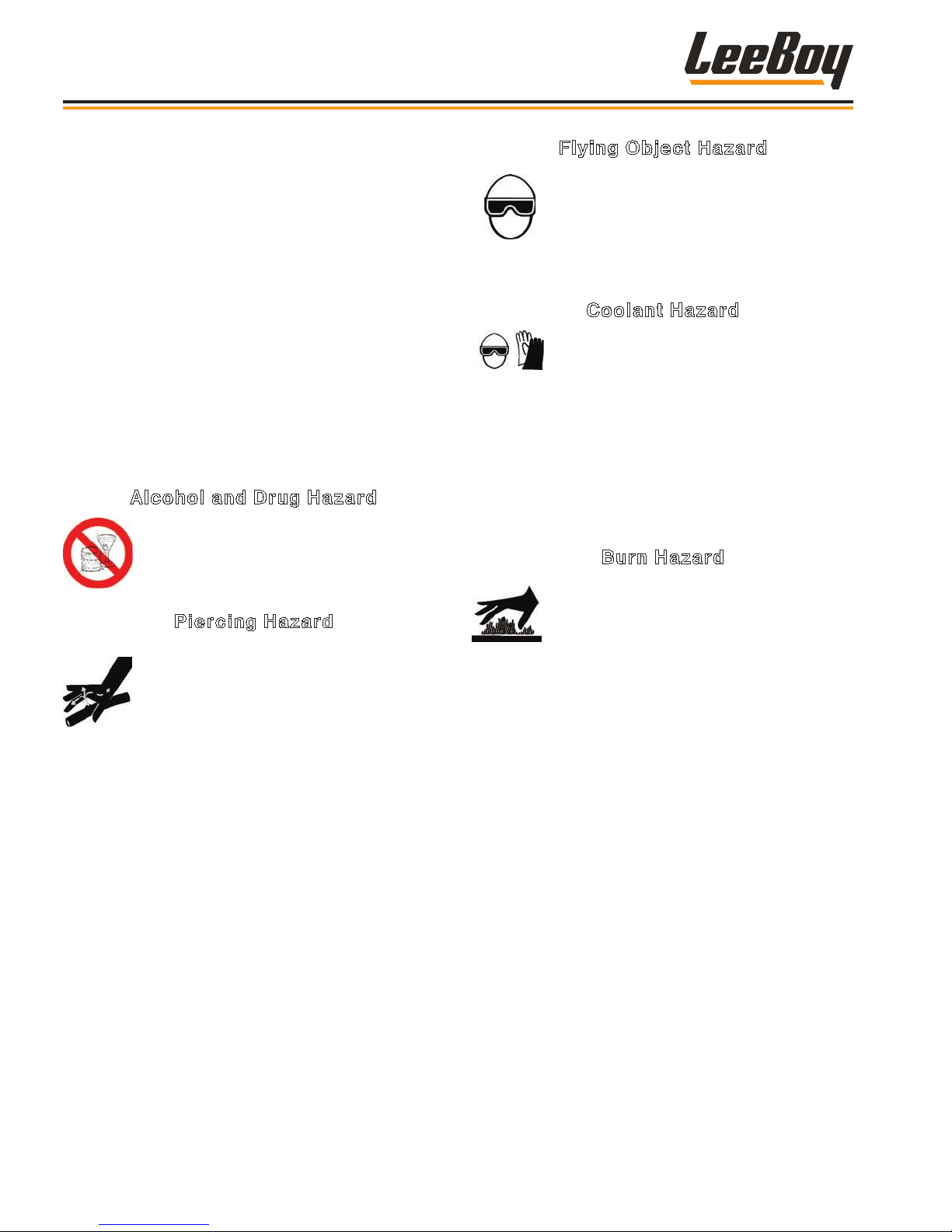
Alcohol and Drug Hazard
Never operate the machine while under the
inuence of alcohol, drugs, or when ill.
Piercing Hazard
High-pressure hydraulic uid or fuel can
penetrate your skin and result in serious
injury. Avoid skin contact with high-pressure
hydraulic uid or diesel fuel spray caused by
a hydraulic or fuel system leak such as a
broken hydraulic hose, fuel injection or high-pressure,
common-rail engine line.
Flying Object Hazard
Always wear eye protection when cleaning
the machine with compressed air or highpressure water.
Dust, ying debris, compressed air,
pressurized water or steam may cause eye
injury.
Coolant Hazard
Coolant must be handled properly to ensure
operator safety.
• Wear eye protection and rubber gloves when handling
engine coolant.
• If contact with the eyes occurs, ush eyes with clean
water for 15 minutes.
• If contact with skin occurs, wash immediately with
soap and clean water.
Burn Hazard
Some of the machine’s surfaces become
very hot during operation and shortly after
shutdown.
• Keep hands and other body parts away from hot
machine surfaces.
• Handle hot components with heat-resistant gloves.
If you are exposed to high-pressure hydraulic uid or
fuel spray, obtain prompt medical treatment.
• Never check for a hydraulic uid or fuel leak with your
hands. Always use a piece of wood or cardboard.
Have your authorized LeeBoy dealer or distributor
repair the damaged parts.
LeeBoy 685D Motor Grader1-6
Page 21
Machine Precautions
Safety
The safety messages that follow have NOTICE level
hazards.
• Any part that is found defective as a result of
inspection or any part whose measured value does
not satisfy the standard or limit must be replaced.
• Always tighten components to the specied torque.
Loose parts can cause damage to the machine or
cause it to operate improperly.
• Only use replacement parts approved by VT LeeBoy.
Other replacement parts may affect warranty
coverage.
Follow the guidelines of the EPA or other
governmental agencies for the proper
disposal of hazardous materials such as
oils, diesel fuel, coolant, etc. Consult the
local authorities or reclamation facility.
• Dispose of hazardous materials in accordance with
all applicable laws and regulations. Never dispose of
hazardous materials by dumping them into a sewer, on
the ground, or into groundwater or waterways.
• Clean all accumulated dirt and debris away from the
body of the grader and its components before you
inspect the grader or perform preventive maintenance
procedures or repairs. Operating a grader with
accumulated dirt and debris will cause premature
wear of grader components. Accumulated dirt and
debris also hinders effective grader inspection.
• Retrieve any tools or parts that may have dropped
inside of the grader to avoid improper grader
operation.
• If any alert indicator illuminates during grader
operation, stop the engine immediately. Determine
the cause and repair the problem before continuing to
operate the grader.
Hot Material Precautions
• Wear protective gear for face, hands, feet, and body
when operating the grader.
• Allow machine to cool before repairing or maintaining
working components.
• If hot asphalt touches skin, ush area immediately with
cold water. DO NOT apply ice to the affected area.
DO NOT ATTEMPT TO REMOVE ASPHALT CEMENT
with products containing solvents or ammonia.
Natural separation will occur in about 48 to 72 hours.
Get medical attention as soon as possible.
• DO NOT remove radiator cap, drain plugs, service
grease ttings, or pressure taps while engine is hot.
Add coolant to the radiator and perform other services
only when the engine is stopped and fully cooled.
• Ensure the machine is properly equipped for
emergencies, i.e., re extinguisher, rst aid kit, etc.
Hydraulic Systems Precautions
• Ensure all components are in good working condition.
Replace any worn, cut, abraded, attened or crimped
hoses and metal lines.
• DO NOT attempt makeshift repairs using tape, clamps
or cements. The hydraulic system operates under
extremely high pressure and such repairs could
cause serious injury.
• Wear proper hand and eye protection when checking
for a high pressure leak. Use a piece of wood or
cardboard as a back stop to isolate and identify leaks.
Hydraulic oil under pressure can
cause serious personal injury. Check for oil leaks
with a piece of cardboard. DO NOT expose hands to
possible high-pressure oil. Turn off engine before
attempting to tighten oil lines and ttings.
1
LeeBoy 685D Motor Grader 1-7
• Escaping pressurized hydraulic uid has force
sufcient to penetrate the skin, which could cause
serious personal injury. Ensure all pressure is
relieved before disconnecting line, hoses or valves.
• If injury from concentrated high pressure steam
or hydraulic uid occurs, seek medical attention
immediately. Injuries resulting from hydraulic uid
penetrating the skin’s surface can result in serious
infections or toxic reactions.
Page 22
Safety
Refueling Precautions
• Do NOT overll the fuel tank as overow creates a re
hazard when spilled on hot components.
• DO NOT smoke when refueling and never refuel when
the engine is running. Fuel is highly ammable and
should be handled with care. Death or serious injury
can occur due to explosion and/or re.
• DO NOT ll tank to capacity. Allow room for expansion
to reduce the risk of fuel expanding and spilling from
the tank.
• Tighten fuel cap securely. Should fuel cap be lost,
replace it with an original manufacturer’s approved
cap. Pressurization of the tank may result from use of
non-approved cap.
• Prevent res by keeping the machine clean of
accumulated debris, grease, and spilled fuel.
• Use ultra-low sulfur diesel fuel (ULSD) only.
Battery Precautions
• Keep all sparks and ames away from batteries, as
gas given off by electrolytes is explosive.
• Acid propelled by an explosion can cause blindness
if it comes in contact with eyes. Always wear safety
glasses when working near batteries.
• If you come in contact with battery electrolyte solution,
wash off immediately. Chemicals can cause burns.
• Always disconnect the battery ground cable before
working on the electrical system to avoid injury from
spark or short circuit. Electrical shock and burns can
occur.
• To avoid electrolyte loss, DO NOT tip batteries more
than 45 degrees.
Starting and Stopping
Precautions
• Check all around the grader to make sure there are
no people working on the machine or in the path of the
machine before starting. DO NOT start until area is
clear. Death or serious injury can occur to bystanders
from being crushed under a moving machine.
• Check brakes, steering and other control devices in
accordance with instructions before starting. Be sure
the engine is in neutral with the park brake engaged.
• DO NOT bypass the grader neutral-start system.
• Be aware of job site conditions and terrain. Adjust
your speed if operating in rough or hilly conditions.
DO NOT operate the engine in an
enclosed area without proper ventilation. Exhaust
gasses are odorless and deadly.
Parking Precautions
• Park grader on level ground whenever possible.
Apply the parking brake. Park the grader with wheels
securely blocked on grades.
• ALWAYS lower the moldboard and any attachments (if
equipped) to the ground.
• Remove ignition key when leaving grader parked or
unattended.
Operating Precautions
• Always comply with local regulations regarding
moving equipment on public roads and highways.
• Know and use the hand signals required for a
particular job. Know who has the responsibility for
signaling.
• Make sure that all lights and reectors comply with
state and local regulations. Make sure that they are
clean, in good working order, and can be seen clearly
by all trafc.
• DO NOT ride on attachments. or allow riders in or on
the grader.
• Check all gauges and warning instruments for proper
operation. If malfunctions are found, shut down the
machine and report the problem for resolution. If
the failure causes loss of steering control, loss of
brake control, or loss of engine power, stop grader
motion as quickly as possible. Apply parking brake (if
equipped). Keep the machine securely parked until
the failure is corrected or the machine can be safely
towed.
• Adjust seat and fasten the seatbelt before driving the
grader. The seat belt must t snug with the holding
strap free of slack.
• Drive the machine with care. Make sure speed is
compatible with conditions. Use caution on rough
ground, slopes, and while turning.
LeeBoy 685D Motor Grader1-8
Page 23
Safety
• Be alert for hazards and obstructions such as ditches,
trees, cliffs, overhead power lines, and areas where
there is danger of a slide.
• Be aware of and understand the job site trafc ow
patterns.
• Obey agmen, road signs, and signals.
• Watch for bystanders. Never allow anyone near the
machine during operation. Never allow anyone to
reach into the machine during use.
• Operator must know how to use signaling devices
when driving the grader. Operator must also
understand which circumstances require use of each
signal. Use tail lights, slow moving vehicle signs, and
warning beacon as needed when traveling on public
roads. It is recommended that you provide an escort
on the road.
• DO NOT tow the grader, except to remove from road
or to load on trailer.
• When moving the machine, adjust speed and direction
of travel for the terrain and ground conditions present.
Always consider adjusting travel speed to match
ground conditions.
• DO NOT stop or turn the grader around on curves
or at the crest of hills. Use extra care when grading
against oncoming trafc.
Snow Removal
• Keep windshield and other windows clean and clear,
using defroster and wipers when needed.
• Use the proper attachment(s) before plowing snow.
Additional equipment may also be needed, i.e., tire
chains, additional warning beacon and/or work lights
and other warning markers.
• Snow removal presents unique hazards, including
slippery road surfaces, poor visibility and other trafc
issues. Be alert for any obstructions covered by snow
that may be hazardous and adjust operating speed
according to slippery conditions.
Storage Precautions
• Store grader in an area away from human activity.
• DO NOT permit children to play on or around the
stored machine. Serious injury or death can occur
from improper/unauthorized use of the machine.
• Make sure the unit is stored on a surface that is rm,
level, and free of debris.
• Store the machine inside a building or cover securely
with a weatherproof tarpaulin.
1
Poor Visibility
Increasingly, road construction equipment is used
during less than ideal lighting conditions such as fog
and smog or at night. These conditions present safety
hazards for workers, bystanders and passing trafc.
When operating under restricted light
conditions, equip the machine with special lighting to
prevent serious injury.
• While the machine is equipped with a beacon and a
work light, contact your authorized LeeBoy dealer for
additional lighting packages if working under these
conditions.
• Use reective tape on the sides of machines when
working at night. Ensure all workers wear reective
safety vests. Use impact barriers (movable or
stationary) to protect workers and direct the trafc
ow safely away from the work site.
Maintenance Precautions
• DO NOT attempt repairs unless trained to do so.
Refer to manuals and experienced repair personnel
for help.
• Before working on the machine, securely block the
machine and any components that may fall. Block
any working components to prevent unexpected
movement while repairs are being made.
• Always wear safety glasses and other required safety
equipment when servicing or making repairs.
• Avoid lubrication or mechanical adjustments while the
grader is in motion or while engine is operating.
• Never make repairs on pressurized components such
as uid lines, the gas system, or mechanical items until
the pressure has been relieved.
• When servicing or replacing hardened pins, use a
brass drift or other suitable material between the
hammer and pin.
• Keep brake and steering systems in good operating
condition.
LeeBoy 685D Motor Grader 1-9
Page 24

Safety
Tire Precautions
DO NOT mount or demount tires
without proper training. A violent explosion can
occur.
Follow all procedures and safety instructions. Charts
containing mounting and demounting instructions are
available from OSHA at www.osha.gov/pls/publications.
Contact your authorized dealer or
a qualied tire dealer or repair service to perform
required tire maintenance.
• Clean rims and repaint to stop corrosion and
facilitate checking air level and tire mounting. Be
careful to clean all dirt and rust from the lock ring
and gutter. This is important to secure lock ring in its
the proper position.
• Check rim components periodically for cracks.
Replace all cracked, badly worn, severely rusted,
and otherwise damaged components with new parts
of the same size and type. If you are not sure about
proper mating of tire and wheel parts, consult your
authorized dealer or a wheel and rim expert.
DO NOT attempt to rework, weld,
heat or braze any rim components that are cracked,
broken or damaged. Replace damaged components
with new parts of the same size and type. Mixing
parts of one type with those of another is potentially
dangerous.
DO NOT reinate a tire that has been
run at without rst inspecting the tire, tube, ap, rim,
and wheel assembly. Double-check the side ring and
O-ring for damage, ensuring they are secured in the
gutter before ination.
Mismatched rim parts are dangerous
and could cause SEVERE injury.
• Remove valve core to exhaust all air from tire.
ALWAYS exhaust all air from tire prior to removing
rim components or wheel components such as nuts
or rim clamps. Check the valve stem by running a
piece of wire through the stem to make sure it is not
plugged.
• DO NOT try to seat rings or other components by
hammering unless tire is fully deated. Doublecheck all components prior to ination.
• DO NOT inate a tire before all components are
properly in place. Recheck components for proper
assembly. If improperly assembled, deate and
correct.
• Never hammer on a tire/rim assembly that is not fully
deated. If assembly is proper at 10 psi (68,947.572
Pa), continue to inate to fully seat the tire beads.
Then completely deate the tire to prevent overly
stretching the tube. Reinate to recommended
operating pressure.
• NEVER sit on or stand in front of a tire/rim assembly
during ination. Use a clip-on chuck and make sure
ination hose is long enough permit the person
inating the tire to stand to the side of the tire.
• DO NOT hammer components with steel hammers.
Use rubber, lead, plastic, or brass-faced mallets to
tap components together.
• DO NOT try to drive an assembled or partiallyassembled tire or rim over a cast spoke wheel by
hammering. DEFLATE and examine to determine
the reason for the improper t. Look for distortion or
components that are not properly locked or sealed.
• Block the tire and wheel on opposite sides of the
vehicle before you place the jack in position. Always
put hardwood blocks under the jack and crib up the
vehicle in case the jack slips.
• DO NOT inate tires beyond the maximum
recommended ination pressure.
• NEVER operate a vehicle on a single tire of a dual
assembly. The carrying capacity of the single tire
and rim is dangerously exceeded and operating a
vehicle in this manner can result in damage to the
rim and tire.
• DO NOT attempt to demount a tire unless you have
the proper equipment and experience to do the job.
LeeBoy 685D Motor Grader1-10
Page 25
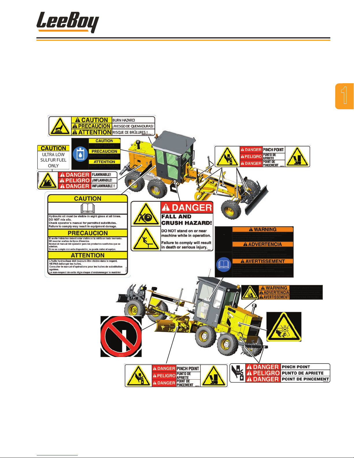
Safety Decals
Safety
If your machine is repainted, it is extremely important
that you replace all the CAUTION, WARNING and
DANGER safety decals in the proper locations. (Figure
1-1) For additional help, refer to the parts listing in
Section 7 and contact your authorized LeeBoy dealer to
order a replacement kit.
NOTE: It is the responsibility of the owner and
operator to make sure that all safety labels are
readable and located on the grader as designated
by LeeBoy.
1
(Both Sides)
(Console)
(Both Sides)
Figure 1-1. Safety Labels and Safety Label Locations
(Both Sides and
Inside Engine Panel)
LeeBoy 685D Motor Grader 1-11
Page 26
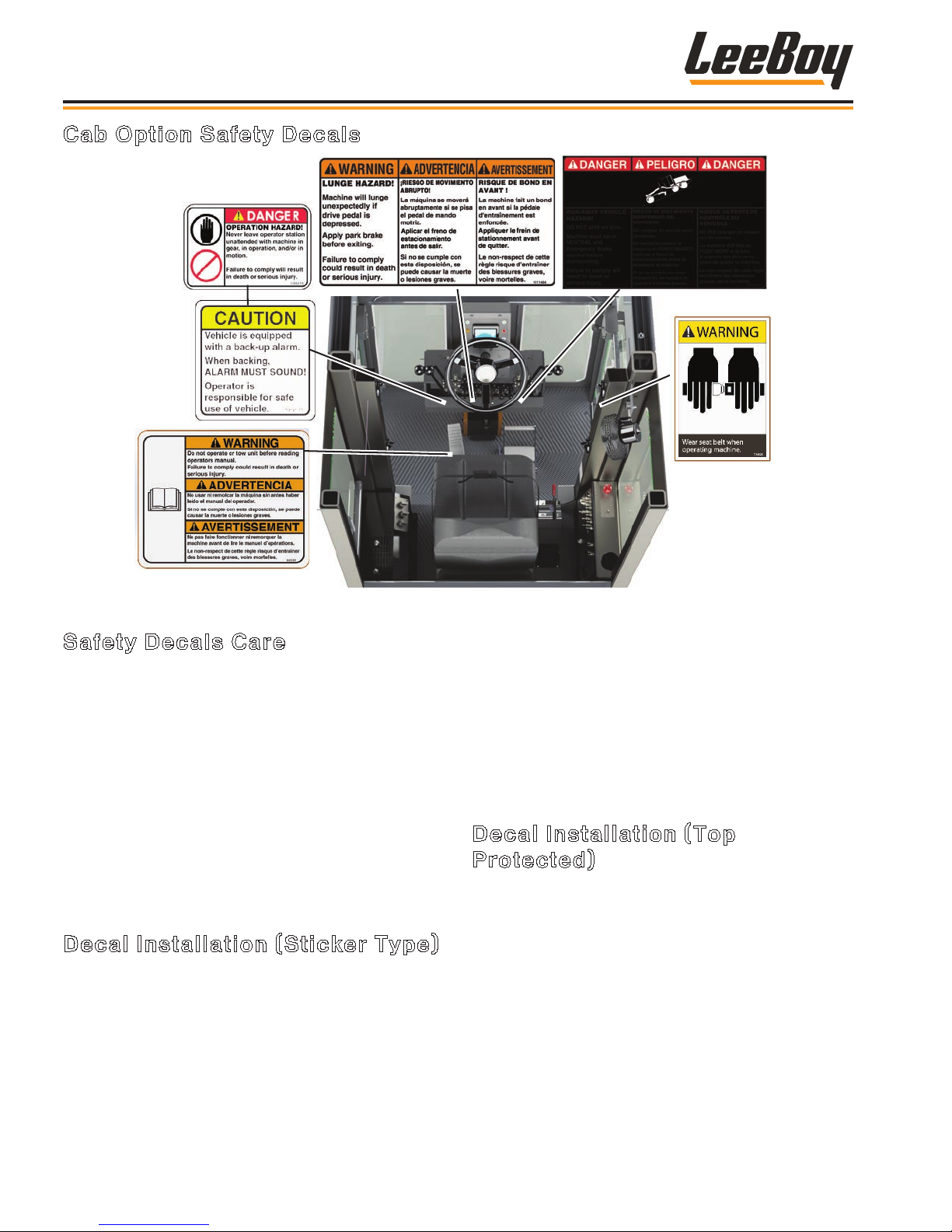
Safety
Cab Option Safety Decals
(Panel Under Seat)
Figure 1-2. Cab Option Additional Safety Decals
Safety Decals Care
1. Keep safety decals and signs clean and legible at all
times.
2. Become familiar with the content and the position
of each safety decal. Decals include important
information.
3. Replace decals and signs that are missing or become
impossible to read.
4. When replacing parts that display a safety decal,
ensure that the new part is tted with a decal as well.
5. Obtain replacement safety decals or signs from your
authorized LeeBoy dealer.
Decal Installation (Sticker Type)
1. Be sure that the installation area is clean and dry. Use
hot, soapy water to clean the surface where the decal
will be applied.
2. Thoroughly dry the surface.
3. Measure and t decal before removing the paper
backing.
4. For decals with no top protection paper, remove the
smallest split-backed paper.
5. Align decal over the specied area and carefully press
exposed portion into place.
6. Slowly remove the remaining backing and carefully
smooth the remaining portion of the decal into place.
7. Small air pockets can be pierced with a pin and
smoothed using a piece of the decal backing.
Decal Installation (Top
Protected)
1. If the decal has a protective top paper, use hot soapy
water on the surface where the decal will be applied.
Leave wet.
2. Determine the proper location, remove protective back
paper and soak decal in clean soapy water before
application. This will help to alleviate air bubbles in the
applied decal.
3. Smooth decal into place with a squeegee and check
for air bubbles.
4. Small air pockets can be pierced with a pin and
smoothed out using a piece of the decal backing.
5. When decal is completely smoothed, carefully remove
top paper.
LeeBoy 685D Motor Grader1-12
Page 27

Section 2
INFORMATION AND SPECIFICATIONS
Page
Limited Warranty Policy . . . . . . . . . . . . . . . . . . . . . . . . . . 2-2
Contact Information . . . . . . . . . . . . . . . . . . . . . . . . . . . . 2-3
Specication Charts . . . . . . . . . . . . . . . . . . . . . . . . . . . . 2-4
Torque Specications . . . . . . . . . . . . . . . . . . . . . . . . . . . 2-8
Standard Inch Fasteners . . . . . . . . . . . . . . . . . . . . . . . 2-8
Metric Fasteners . . . . . . . . . . . . . . . . . . . . . . . . . . . 2-9
Hydraulic Fittings . . . . . . . . . . . . . . . . . . . . . . . . . . 2-9
Determining Proper Torque . . . . . . . . . . . . . . . . . . . . . 2-10
2-1LeeBoy 685D Motor Grader
Page 28

Information and Specications
ONE YEAR LIMITED WARRANTY
Limited Warranty
If a manufacturing defect in factory supplied materials or factory
workmanship is found and the authorized LeeBoy dealer (“Dealer”)
is notied during the warranty period, LeeBoy will be responsible for
repairing or replacing any part or component of the unit or part that
fails to conform to the warranty during the warranty period.
Terms and Conditions
The warranty applies for a period of one year (for unlimited hours of
usage on the unit during the one year), beginning on the date that
the Dealer from which the unit is purchased submits the warranty
registration form to LeeBoy (typically on the date of purchase).
The warranty is not transferable and applies only to the original
purchaser of a new unit from a Dealer.
Warranty work must be performed at an authorized Dealer location.
LeeBoy has the right to repair any component or part before
replacing it with a new one.
Replacement parts furnished by LeeBoy are covered for the
remainder of the warranty period applicable to the unit or
component in which such parts are installed.
All new replacement parts purchased from a Dealer will carry a six
(6) month warranty.
Items Not Covered
LeeBoy is not responsible for the following:
• All used units or used parts of any kind.
• Repairs due to normal wear and tear or brought about by abuse
or lack of maintenance of the machine.
• Attachments not manufactured or installed by LeeBoy.
• Liability for incidental or consequential damages of any type
including, but not limited to, lost prots or expenses of acquiring
replacement equipment.
Exclusions and Limitations
VT LeeBoy has no obligation under this warranty for any defects or
failures caused by:
• Misuse, misapplication, negligence, accident or failure to maintain
or use in accordance with the most current operating instructions;
• Unauthorized alterations or modications;
• Any replacement parts or attachments not manufactured by or
expressly approved by LeeBoy;
• Failure to conduct normal maintenance and operating service,
including without limitation, providing lubricants, coolant, fuel, tuneups, inspections or adjustments; or
• Unreasonable delay, as determined by LeeBoy, in making the
applicable units or parts available upon notication of a service
notice ordered by LeeBoy.
LeeBoy is not responsible for any of the following:
• Defects or failures with respect to any engine or truck chassis;
• Defects or failures covered by a warranty provided by a third-party,
including without limitation warranties with respect to engines or
truck chassis;
• Costs related to travel time, mileage or overtime;
• Costs related to transporting the unit to and from the place at which
warranty work is performed;
• Airfreight charges related to transporting repair parts to the place at
which warranty work is performed;
• Used units or used parts of any kind;
• Repairs due to normal wear and tear, or brought about by abuse or
lack of maintenance of the equipment, except for premature failures;
• Attachments not manufactured or installed by LeeBoy; or
• Miscellaneous charges.
Exclusion of Other Warranties/Limitation of Liability
OTHER THAN THE EXPRESS WARRANTY PROVIDED IN SECTION A. ABOVE, LEEBOY GIVES NO EXPRESS, STATUTORY, OR
IMPLIED WARRANTY OR GUARANTEE AND HEREBY DISCLAIMS ALL SUCH WARRANTIES, INCLUDING WITHOUT LIMITATION
ANY IMPLIED WARRANTY OF MERCHANTABILITY, FITNESS FOR A PARTICULAR PURPOSE, SUITABILITY, DURABILITY,
CONDITION, QUALITY, OR FREEDOM FROM CLAIMS OF ANY PERSON BY WAY OF INTERFERENCE, INFRINGEMENT, OR THE
IN NO EVENT OR UNDER ANY THEORY OF RECOVERY, WHETHER AS A RESULT OF BREACH OF CONTRACT OR WARRANTY,
ALLEGED NEGLIGENCE, OR LIABILITY WITHOUT FAULT, SHALL LEEBOY BE LIABLE FOR ANY SPECIAL, INCIDENTAL OR
CONSEQUENTIAL DAMAGES ARISING OUT OF THE SALE, USE, OR LOSS OF USE OF ANY PRODUCT, INCLUDING WITHOUT
LIMITATION LOST PROFITS OR REVENUES, COST OF CAPITAL, COST OF SUBSTITUTED EQUIPMENT, FACILITIES OR SERVICES,
DOWNTIME COSTS, LABOR COSTS, OR DIMINUTION OF VALUE.
2-2
LIKE.
LeeBoy 685D Motor Grader
Page 29
CONTACT INFORMATION
Information and Specications
For information regarding parts and repairs about your
machine, contact your authorized LeeBoy dealer. If your
dealer is unable to resolve the problem, contact LeeBoy
directly.
Sales Representative:
Dealership Name:
Dealership Address:
Dealership Phone:
Record dealer information in the space provided.
For additional information about LeeBoy, please visit:
www.leeboy.com.
Record of Ownership
Please complete the following information for use if you need to contact LeeBoy for service, parts or literature.
Machine Model Number:
Product Serial Number:
Date of Purchase:
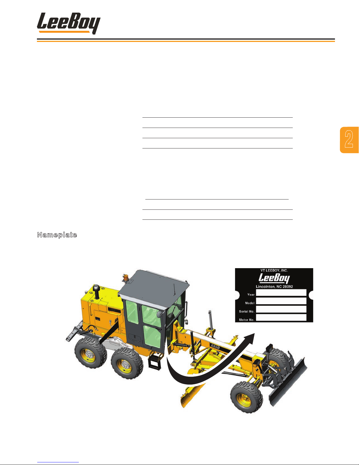
Nameplate
2
The nameplate contains the model and serial numbers used to identify the machine and its components for parts or
service information. Refer to the Engine Operator’s Manual for the location of the engine nameplate.
LeeBoy 685D Motor Grader
Figure 2-1. Nameplate Location
2-3
Page 30
Information and Specications
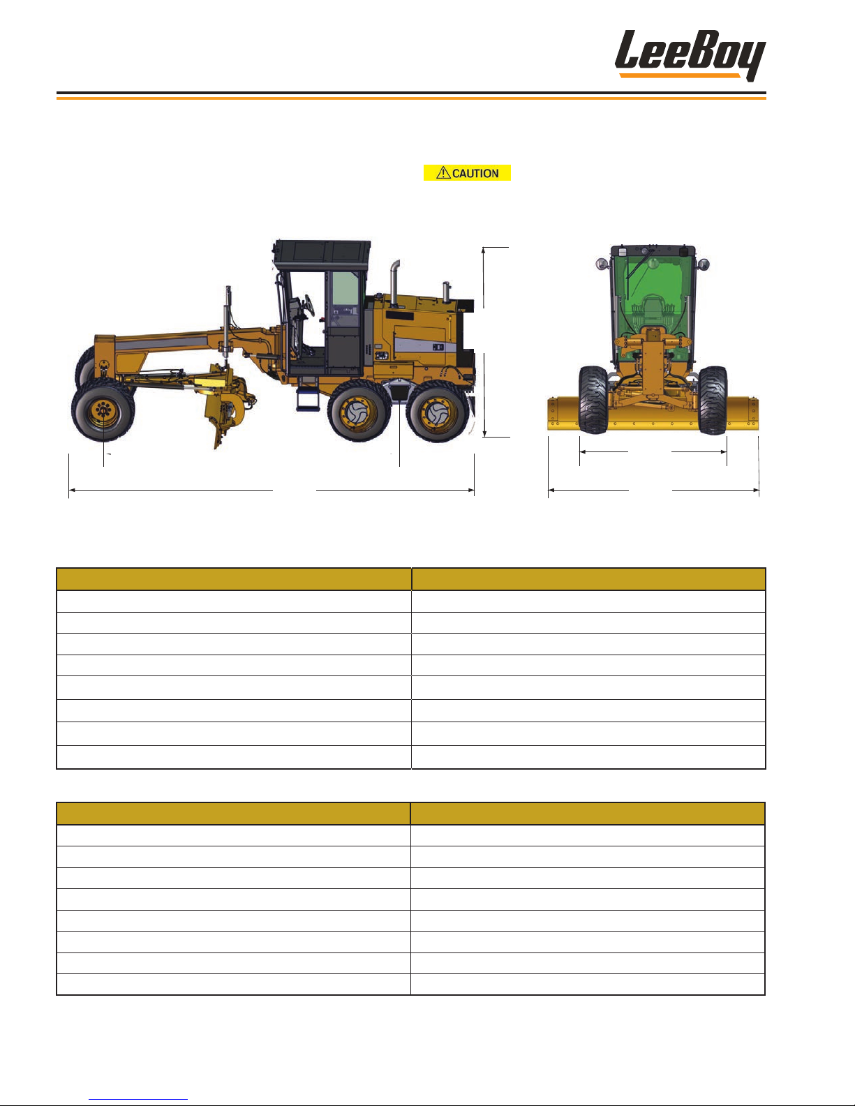
SPECIFICATION CHARTS
The specications provided in this section include
screed weights, dimensions, performance, and torque
values for both metric and standard inch fastener.
16’ 1”
(4.9 m)
22’ 3”
(6.8 m)
Table 2-1. Machine Dimensions
Replace original equipment only with
components approved by LeeBoy.
10’ 2”
(3.1 m)
7’ 8”
(2.3 m)
11’
(3.35 m)
ITEM SPECIFICATION
Base Overall Length 22 ft 3 in (6.8 m)
Overall Height with Beacon 10 ft 2 in (3.1 m)
Overall Width (Outside Front Tires) 7 ft 8 in (2.37 m)
Overall Width (Moldboard ) 11 ft (3.3 m)
Base Weight 16,000 lbs (7257.47 kg)
Wheelbase 16 ft 1 in (4.9 m)
Outside Turning Radius 22 ft (6.7 m)
Minimum Ground Clearance 1 ft (30.4 cm)
Table 2-2. Engine Specications
ITEM SPECIFICATION
Model Cummins 3.8 Tier 4F
Engine Type 4-Cylinder, Water-Cooled Diesel
Horsepower 130 HP @ 2200 RPMs (97 kW)
Displacement, Bore and Stroke 229 cu in (3.8 L); 4.02 in (102 mm); 4.53 in (115 mm)
High Idle Speed 2200 RPMs
Maximum Gross Torque 360 ft lbs (488 N•m)
Maximum Gross Torque 360 ft lbs
Idle Speed 1200 RPMs
2-4
LeeBoy 685D Motor Grader
Page 31

Information and Specications
Table 2-3. Electrical Specications
ITEM SPECIFICATION
Batteries (2) 12 VDC, Maintenance Free
Cold Cranking Amps (CCA) 800 CCA Per Battery (1600 CCA Total)
Alternator 135 amp
Table 2-5. Operational Specications
ITEM SPECIFICATION
Travel Speed (@ 2200 RPMs) 0 - 20 mph (0- 32.2 kph)
Recommended Speed While Grading 0 - 10 mph (0 - 16 kph)
Table 2-6. Fuel and Lubricant Specications
ITEM SPECIFICATION
Engine Oil API CJ-4 or ACEA-E9 (Low Ash) 15W40 WT
Hydraulic Oil AW32 or AW68 Hydraulic Oil
Coolant Ethylene/Glycol or Propylene Glycol
Fuel Ultra Low Sulphur Diesel (ULSD)
Transfer Case (2-Speed) 80-90 WT Gear Oil
Tandem Gear Box 80-90 WT Gear Oil
Differential Oil 80-90 WT Gear Oil
Planetary Hub 80-90 WT Gear Oil
Grease Shell Avania EP Grease or Equivalent
Table 2-7. Machine System Capacity Specications
ITEM SPECIFICATION
Fuel 45 gal (170.3 L)
Engine Lubrication Oil 15.4 qt (14.6 L)
Engine Coolant 5.75 gal (22 L)
Hydraulic Oil Reservoir 30 gal (113.56 L)
Transfer Case (2-Speed) .92 gal (3.48 L)
Differential Oil 2.2 gal (8.4 L)
Planetary Hub .63 gal (2.4 L) per hub
Tandem Gear Box 2.32 gal (8.78 L) per side
2
ITEM SPECIFICATION
Tires 15-19.5 TL 8PR; 30 PSI
Brakes
Front Drive Axle
LeeBoy 685D Motor Grader
Table 2-8. Chassis Specications
Foot-Operated, hydrostatic traction drive system.
Hydraulic park brake is electrically actuated.
Oscillating axle supported by tapered roller bearings
and bushings. Wheel lean 15° left or right. Ground
clearance of 1.2 feet (.36 m)
2-5
Page 32

Information and Specications
Table 2-9. Hydraulic Specications
ITEM SPECIFICATION
Traction Pump Variable Piston 4.58 cu in (75 cu cm)
Function Pump Gear 0.93 cu in (15.2 cu cm)
Steering Pump Gear 0.93 cu in (15.2 cu cm)
Drive Motor Variable Volume 4.8 cu in (80 cu cm)
Hydraulic Filters Remote Pressure and Return
Table 2-10. System Pressures
ITEM SPECIFICATION
Operating Pressure 0 - 6000 psi (0 - 414 Bar)
Accumulator 2300 psi (158.579 Bar)
Accumulator Low-Pressure Switch 1300 psi (89.6 Bar)
Relief Valve 3000 psi (206.8 Bar)
Charge Valve to Orbital (At Relief) 2465 psi (170 Bar)
10-Section Valve 1900psi (131 Bar)
Main Drive Pump 6000 psi (413.68 Bar)
Charge Pressure 350 psi (24 Bar)
Park Brake Release 350 psi (24 Bar)
Table 2-11. Moldboard Specications
ITEM SPECIFICATIONS
Width and Height
Side Shift, Tilt and Rotation 3 ft (.91 m); 30° Tilt; 64° Rotation
Penetration 1 ft 2 in (.365 m)
Raised Clearance 1 ft 1 in (.335 m)
Table 2-12. Front Blade Specications
ITEM SPECIFICATION
Width and Height
Raised Clearance 1.9 ft (.533 m)
Penetration 6 in (15.1 cm)
Table 2-13. Rear Scarier Specications
ITEM SPECIFICATION
Width 6 ft (1.8 m)
Number of Teeth 9
Raised Clearance
Penetration
Width: 11 ft (3.3 m)
Height: 1 ft 9 in (.579 m)
Width: 8 ft (2.4 m)
Height: 1.3 ft (.381 m)
Low: 11.5 in (29 cm)
High: 13.7 in (34 cm)
Low: 8.5 in (21 cm)
High: 6 in (15 cm)
2-6
LeeBoy 685D Motor Grader
Page 33
TORQUE SPECIFICATIONS
Information and Specications
The following tables list torque values for standard
hardware. This is a guide for average application
involving typical stresses and machined surfaces.
Values are based upon physical limitations of clean,
plated and lubricated hardware. Under more extreme
conditions, individual torque value should be followed.
Conversion formulas are provided in the adjacent table:
ft-lb to N•m [ft-lb]*1.3558 = [N•m)
ft-lb to in-lb [ft-lb]*12 = [in-lb]
N•m to in-lb [N•m]*8.8508 = [in-lb]
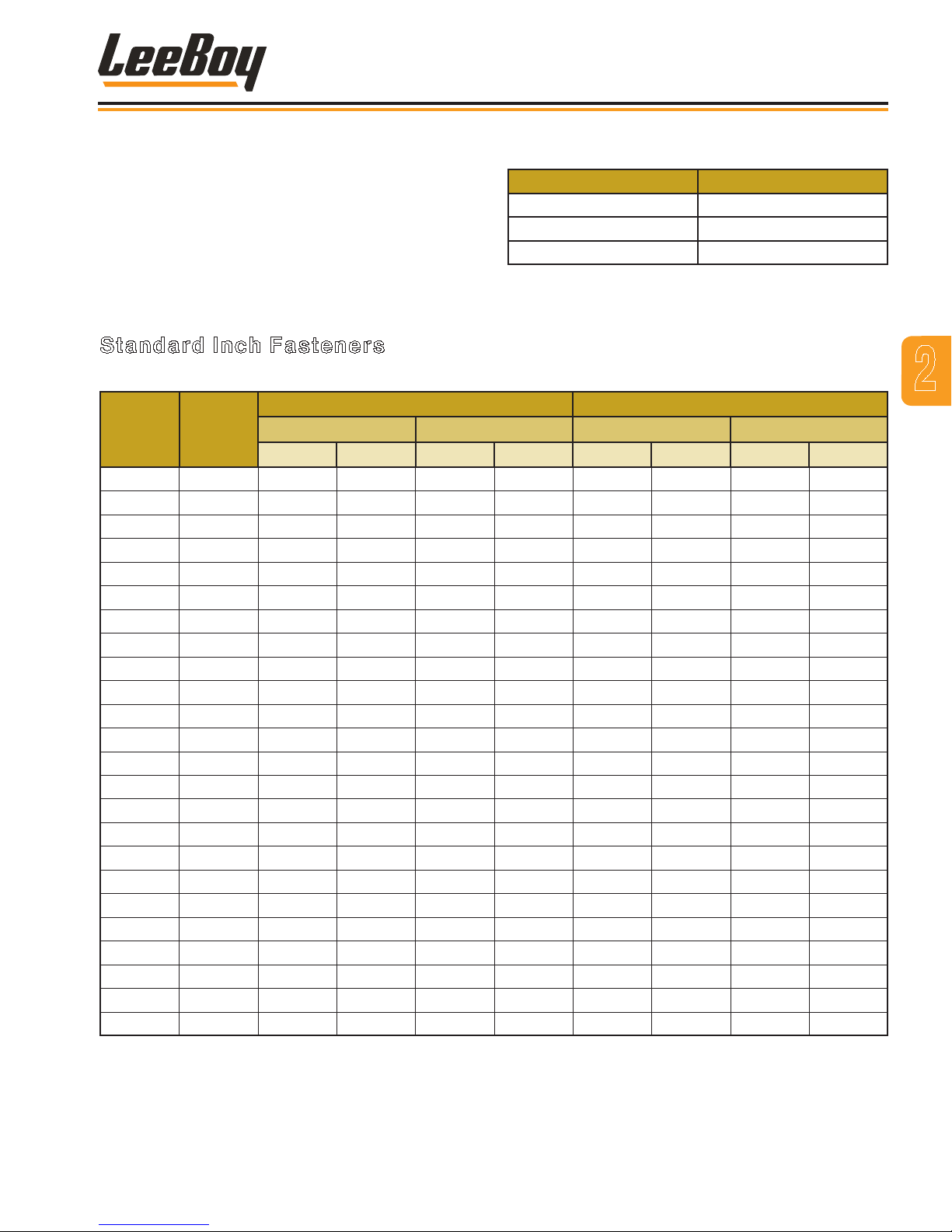
Conversion Formula
Standard Inch Fasteners
Table 2-14. Torque Specications For Standard Inch Fasteners
CAPSCREWS: SAE GRADE 5 CAPSCREWS: SAE GRADE 8
SIZE THREAD
1/4 20 UNC 8 6 11 8 12 9 16 12
28 UNF 10 7 14 9 14 10 19 14
5/16 18 UNC 17 13 23 18 25 18 34 24
24 UNF 19 15 26 20 27 20 37 27
3/8 16 UNC 31 23 42 31 44 33 60 45
24 UNF 35 26 47 35 49 37 66 50
7/16 14 UNC 49 37 66 50 70 52 95 71
20 UNF 55 41 75 56 78 58 106 79
1/2 13 UNC 75 57 102 77 106 80 144 108
20 UNF 85 64 115 87 120 90 163 122
9/16 12 UNC 109 82 148 111 154 115 209 156
18 UNF 121 91 164 123 171 128 232 174
5/8 11 UNC 150 113 203 153 212 159 287 216
18 UNF 170 127 230 172 240 180 325 244
3/4 10 UNC 267 200 362 271 376 282 510 382
16 UNF 297 223 403 302 420 315 569 427
7/8 9 UNC 429 322 582 437 606 455 822 617
14 UNF 474 355 643 481 669 502 907 681
1 8 UNC 644 483 873 655 909 681 1232 923
14 UNF 722 542 979 735 1020 765 1383 1037
1-1/4 7 UNC 1121 840 1520 1139 1817 1363 2464 1848
12 UNF 1241 930 1683 1261 2012 1509 2728 2046
1-1/2 6 UNC 1950 1462 2644 1982 3162 2371 4287 3215
12 UNF 2194 1645 2975 2230 3557 2668 4823 3617
TORQUE (ft lb) TORQUE N•m TORQUE (ft lb) TORQUE N•m
Dry Lubed Dry Lubed Dry Lubed Dry Lubed
2
LeeBoy 685D Motor Grader
2-7
Page 34
Information and Specications
Metric Fasteners
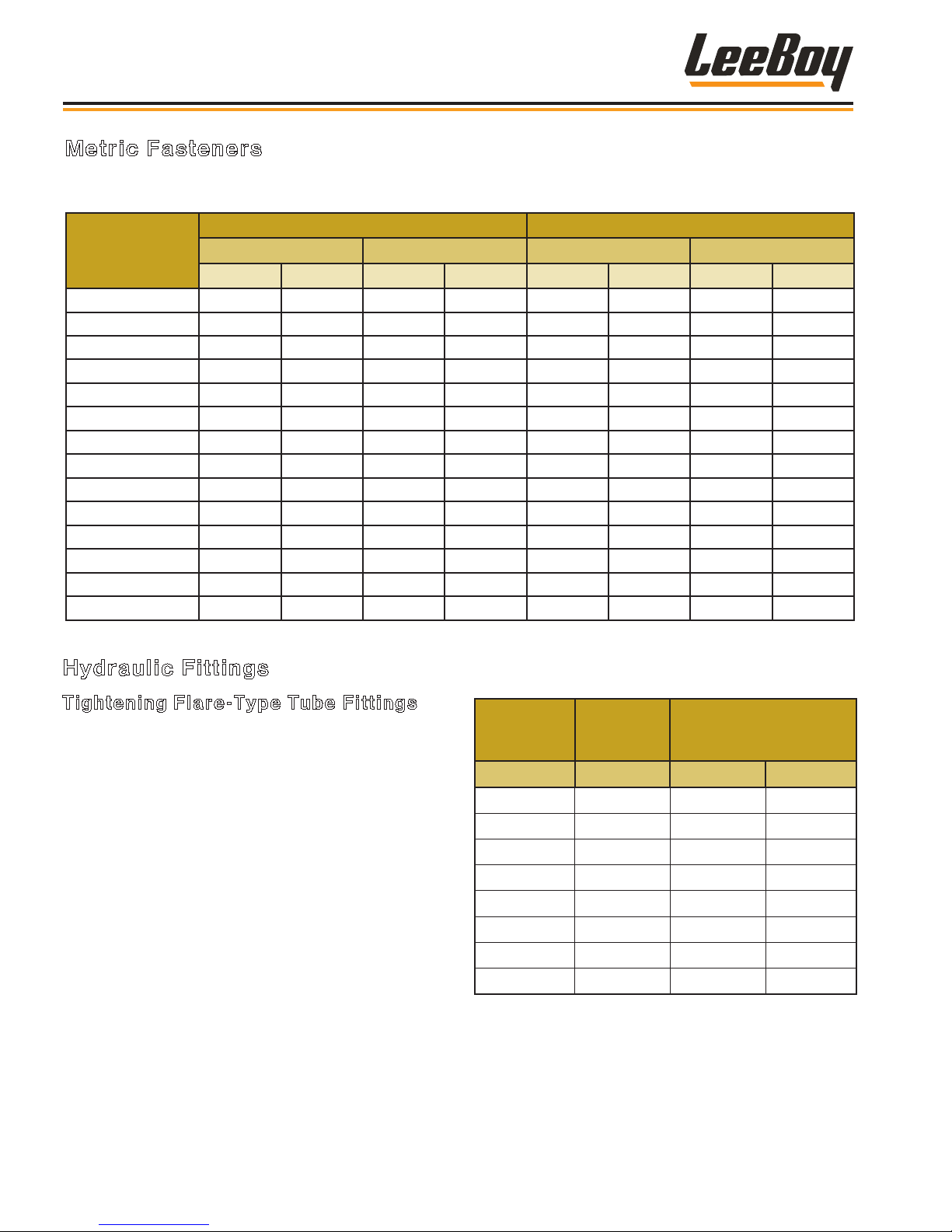
Table 2-15. Torque Specications for Metric Fasteners
CLASS 8.8 [GRADE 5 EQUIVALENT] CLASS 10.9 [GRADE 8 EQUIVALENT]
NOMINAL SIZE
AND PITCH
M4 x 0.7 2 2 3 2 3 2 4 3
M5 x 0.8 5 3 7 4 7 5 9 7
M6 x 1 8 6 11 8 11 8 15 11
M8 x 1.25 19 14 26 19 27 20 37 27
M10 x 1.5 37 28 50 38 53 40 72 54
M12 x 1.75 65 49 88 66 93 70 126 95
M14 x 2 104 78 141 106 148 111 201 150
M16 x 2 161 121 218 164 230 173 312 235
M18 x 2.5 222 167 301 226 318 239 431 324
M20 x 2.5 314 236 426 320 449 337 609 457
M22 x 2.5 428 321 580 435 613 460 831 624
M24 x 3 543 407 736 552 777 582 1053 789
M27 x 3 796 597 1079 809 1139 854 1544 1158
M30 x 3.5 1079 809 1463 1097 1544 1158 2093 1570
TORQUE (ft lb) TORQUE N•m TORQUE (ft lb) TORQUE N•m
Dry Lubed Dry Lubed Dry Lubed Dry Lubed
Hydraulic Fittings
Tightening Flare-Type Tube Fittings
1. Check the are and are seat for defects that might
cause leakage.
2. Align tube with tting before tightening.
3. Lubricate connection.
4. Hand tighten swivel nut until snug.
5. To prevent twisting the tube(s), use two wrenches.
Place one wrench on the connector body and
tighten the swivel nut with the second to the torque
shown in the following table:
NOTE: The torque values shown are based upon
lubricated connections.
Table 2-16. Torque Specications for Steel Flare
Type Tube Fittings
TUBE SIZE
OUTER
DIAMETER
(IN) (IN) (LB FT) (N•m)
3/16 7/16 8 11
1/4 9/16 12 16
5/16 5/8 16 22
3/8 11/16 23 31
1/2 7/8 38 52
5/8 1 54 73
3/4 1 1/4 75 102
7/8 1 3/8 83 113
NUT SIZE
ACROSS
FLATS
TORQUE VALUE
2-8
LeeBoy 685D Motor Grader
Page 35
Determining Proper Torque
LA
L
E
LA
LH
The only reliable method of creating a consistently
leak-free and long-lasting connection is to ensure the
coupling is brought to the proper torque. Using a torque
wrench with crowfoot is the best method, but the ats
method can be used if a torque wrench is not available.
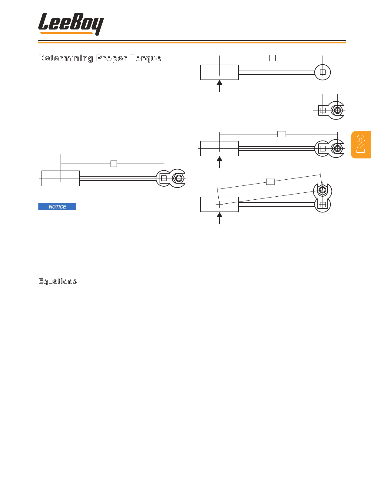
The most straightforward method of determining the
correct torque setting is to multiply the desired torque
by the length of the wrench from the center of the handle
to the center of the drive (L); divided by the length of the
wrench from the center of the handle to the crowfoot
center (LA) as shown below:
L
Figure 2-2. Torque Wrench - Crowfoot
Information and Specications
2
The minimum torque values are
adequate for sealing most applications. Maximum
torque values should never be exceeded.
There are several methods of determining the correct
setting on the torque wrench when using a crowfoot. All
of the methods involve making the setting proportional
to the effective change in length of the wrench multiplied
by the desired nal torque. The equations and
illustration below describe proper measurements.
Equations
• Torque setting if the crowfoot is placed in line with
respect to the wrench:
TS = TD * L / LA
OR
TS = TD * L / (L+E)
• Torque setting if the crowfoot is placed at 90° with
respect to the wrench
TS = TD * L / LH
OR
TS = TD * L / √(L2 + E2)
• To estimate the crowfoot size (E)
Figure 2-3. Measurements Needed
LEGEND
L = Distance from center of torque wrench handle to the
center of socket drive
E = Distance from center of socket drive to the center of
crowfoot
LA = Distance from center of torque wrench handle to
the center of crowfoot
LH = Distance from center of torque wrench handle to
the center of crowfoot, when mounted at 90°
TD = Desired torque at the tting
TS = Torque setting indicated on wrench
E = Drive Size * 0.5 + Distance between Drive and
Open End + Wrench Size * 0.5774
LeeBoy 685D Motor Grader
2-9
Page 36
Mark Line on Nut
Information and Specications
Coupling Installation
Use the following steps for proper coupling installation:
1. Determine the correct torque value for your
coupling.
NOTE: Only use the torque values specied from
the manufacturer. DO NOT use SAE torque
recommendations.
2. Ensure the seal face and threads are clean and in
good condition. O-Rings should be lubricated with
light oil, but threads should be completely dry unless
making pipe thread connections (interference seal).
NOTE: Attach the male end of the hose onto the
equipment rst since it may be necessary to
rotate the entire hose assembly to tighten
the male threads. Then route the hose into
position while avoiding twisting the hose.
3. Tighten the connection (by hand), bringing the seal
face into contact and rotating the nut until it stops.
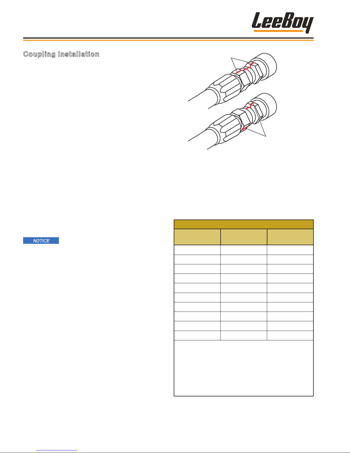
4. Mark a line across the coupling nut and backup hex
for the ats method verication of coupling torque.
5. Apply a wrench to the backup hex to prevent the
coupling and hose from moving while tightening the
nut with a torque wrench.
Failure to retain the backup hex during
installation will also result in additional clamp load
force that could cause damage to the seal face.
NOTE: The coupling nut must be in motion for an
accurate torque reading. If the nut is stopped
before nal torque value is achieved, it must
be loosened and retightened until the torque
is attained while the nut is in motion.
If a torque wrench cannot t into the coupling area or if
it is unavailable, the ats method may be used to ensure
that the coupling is properly tightened.
Example 2 Flats
difference
Figure 2-14. Flats Method Tightening
NOTE: The mark placed on the nut and backup hex
after tightening by hand should rotate during
nal tightening according to the table below.
The nut and backup hex can then be marked
to indicate if the coupling loosens over time.
Table 2-17. Flats Method Values for Selected
Terminations
FLATS METHOD VALUES
Termination
Type
JIC -4 1.5 - 1.75
JIC -6 1.0 - 1.5
JIC -8 1.5 - 1.75
JIC -10 1.0 - 1.5
JIC -12 1.0 - 1.5
JIC -16 .75 - 1.0
JIC -20 .75 - 1.0
JIC -24 .75 - 1.0
JIC -32 .75 - 1.0
JIS -4 .5 - 1.5
1. Seal faces must be in contact with the tting fully
tightened by hand before marking ats.
2. The ats method is most accurate for the rst
assembly cycle. For multiple disassembly and
assembly cycles, torque values are more reliable.
Dash Size Flats
2-10
3. Tightening two (2) ats or more may damage seal
faces.
LeeBoy 685D Motor Grader
Page 37

Information and Specications
Table 2-18. Torque Specications For US Style Coupling Terminations
JIC, SAE 45°, ORFS, O-RING BOSS, GATES ADAPTERLESS AND MEGASEAL
JIC 37°, SAE 45°
DASH
SIZE
-3 8 10
-4 10 11 5 6 10 12 14 16 14 16
-5 13 15 7 9 18 20
-6 17 19 12 15 18 20 24 26 24 26
-8 34 38 20 24 32 40 37 44 50 60
-10 50 56 34 40 46 56 50 60 72 80
-12 70 78 53 60 65 80 75 83 125 135
-14 65 80 160 180
-16 94 104 74 82 92 105 111 125 200 220
-20 124 138 75 83 125 140 133 152 210 280
-24 156 173 79 87 150 180 156 184 270 360
-32 219 243 158 175
& Mega-Seal
(Steel)
Min Max Min Max Min Max Min Max Min Max
JIC 37°, SAE 45°
& Mega-Seal
(Brass)
Flat Face O-Ring
Seal (Steel)
SAE O-Ring Boss
(Steel) & Gates
Adapterless
≤ 4000 PSI
SAE O-Ring Boss
(Steel) & Gates
Adapterless
> 4000 PSI
2
Table 2-19. Torque Specications for DIN 24, DIN 60,
and Inverted Cone Style Coupling Terminations
DIN 24, DIN 60, AND INVERTED CONE
Size (mm) Torque (lb ft)
Light
Series
Tube OD
6 7 15
8 15 26
10 8 18 30
12 10 22 33
14 12 26 37
15 14 30 52
18 20 44 74
22 25 59 89
28 30 74 111
35 133 184
42 148 221
Heavy
Series
Tube OD
16 30 52
38 74 162
Min Max
Table 2-20. Torque Specications for 4-Bolt
Flange Connections
4-BOLT FLANGES
Dash Size Bolt Size (in) Torque (lb ft)
-8 0.31 17
-12 0.38 26
-16 0.44 43
-20 0.50 65
-24 0.63 130
-32 0.75 220
1. Align faces and tighten bolts (by hand) before
applying nal torque in a pattern. The seal faces
must be parallel with an even bolt tension to seal
properly.
2. Torque values apply to bolts that are plated or
coated in light engine oil.
3. Before assembly, lubricate O-Ring with light oil
(SAE 10W or 20W).
LeeBoy 685D Motor Grader
2-11
Page 38

Information and Specications
Table 2-21. Torque Specications for NPTF Dry Seal
Pipe Threads
NPTF
Dash Size Max Torque (ft-lb)
-2 20
-4 25
-6 35
-8 45
-12 55
-16 65
-20 80
-24 95
-32 120
1. The torque values obtained from tightening pipe
threads can vary considerably depending upon
thread condition. Adequate sealing can occur at
values much lower than the maximum values listed
above. Only enough torque to achieve adequate
sealing should be used.
2. When using a male tapered pipe thread with a
female straight or parallel pipe thread, maximum
values are 50% of those listed in the table above.
Table 2-22. Torque Specications for BSP 30°
Inverted Cone and JIS Coupling Terminations
BSP 30° INVERTED CONE AND JIS
Torque (ft-lb)
Dash Size
Min Max
-2 7 9
-4 11 18
-6 19 28
-8 30 36
-10 37 44
-12 50 60
-16 79 95
-20 127 152
-24 167 190
-32 262 314
3. If thread sealant is used, maximum values shown
should be decreased by 25%.
2-12
LeeBoy 685D Motor Grader
Page 39
Section 3
COMPONENT LOCATION
Page
Component Location . . . . . . . . . . . . . . . . . . . . . . . . . . . . . 3-1
Components Overview . . . . . . . . . . . . . . . . . . . . . . . . . . . 3-3
Operator Station . . . . . . . . . . . . . . . . . . . . . . . . . . . 3-3
Engine . . . . . . . . . . . . . . . . . . . . . . . . . . . . . . . . 3-3
Hydrostatic Drive . . . . . . . . . . . . . . . . . . . . . . . . . . 3-4
Electrical System . . . . . . . . . . . . . . . . . . . . . . . . . . 3-4
Scarier (Optional) . . . . . . . . . . . . . . . . . . . . . . . . . . 3-5
Standard Equipment/Options . . . . . . . . . . . . . . . . . . . . 3-5
Machine Overview . . . . . . . . . . . . . . . . . . . . . . . . . . . . . 3-6
Operator Station . . . . . . . . . . . . . . . . . . . . . . . . . . . . . . 3-7
Steering Column Controls . . . . . . . . . . . . . . . . . . . . . . . . . 3-8
Main Control Panel . . . . . . . . . . . . . . . . . . . . . . . . . . . . . 3-10
Heat and Air Conditioning (Cab Option) . . . . . . . . . . . . . . . . . . . 3-12
3
3-1LeeBoy 685D Motor Grader
Page 40

Components
NOTES
LeeBoy 685D Motor Grader3-2
Page 41
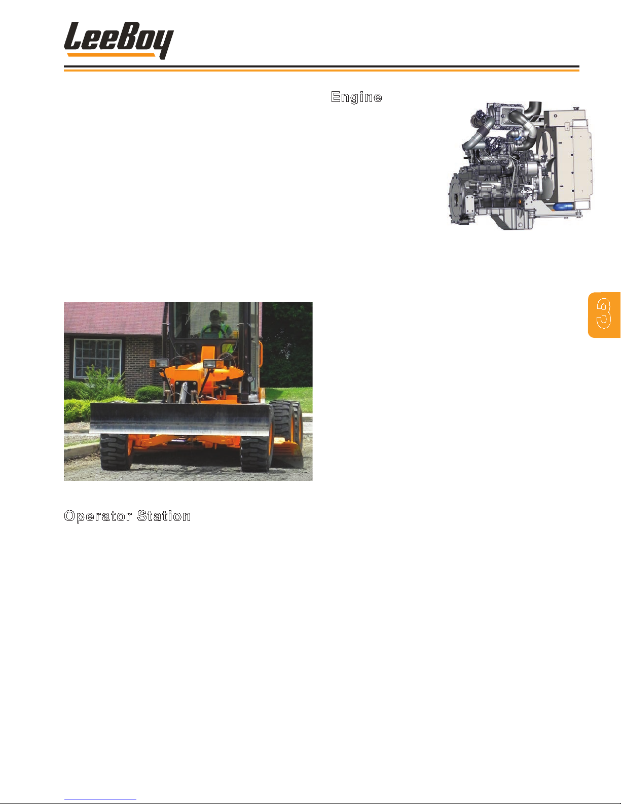
Components
COMPONENTS OVERVIEW
The LeeBoy 685D Motor Grader is a compact motor
grader with the functionality of a large motor grader.
It’s versatility and specialized applications include
spreading base materials, ditch and shoulder projects,
ne grading, medium cutting and even snow removal.
Graders can also be used for bank sloping, leveling,
crowning, and road/runway maintenance. This selfpropelled, wheeled grader has an adjustable, 11-foot
(3.35 meter) moldboard blade positioned between the
front and rear wheels. An optional 12-foot (3.65 meter)
moldboard is also available. Optional attachments
include an 8-foot (2.4 meter) front blade, front or rear
scariers or a blade-mounted, ip-down scarier. Be
familiar with all the grader’s components and optional
attachments purchased before operating this machine.
Engine
The 685D Motor Grader
is equipped with a
Cummins QSF3.8 Tier
4F diesel engine. This
Tier 4 Final fuel-efcient
engine offers the latest
in innovative emission
solutions to reduce diesel
particulate matter (DPM)
and other toxins released
into the air.
Advanced emission-control devices and low-sulfur fuel
requirements--only Ultra-Low Sulfur Diesel (ULSD)
can be used in this engine--combine with new after-
treatment methods. The SCR system is an efcient,
effective means of ltering dirt and other contaminates
for optimum engine performance and reducing air
pollution from exhaust emissions. The Selective
Catalytic Reduction (SCR) system precisely injects
Diesel Exhaust Fluid (DEF) into the engine’s exhaust
system to transform those toxic exhaust gases into
harmless water vapor and nitrogen. SCR technology is
also cost-effective and fuel-efcient.
3
Operator Station
The 685D Motor Grader is equipped with a canopy, but
an optional fully-enclosed cab version offers additional
operator comfort on the job site. Air conditioning,
heating, and other options are also available for a cab
model.
Levers, control switches and joystick controls are within
easy reach for operator comfort. The PV485 digital
controller unit on the steering control panel includes
throttle control, tachometer, fuel gauge, oil pressure
gauge, coolant temperature, voltmeter and hour meter
along with gauges and warning alerts. The steering
column can be tilted for comfort. Complete control
panel information is described in the following pages.
The High-Pressure Common Rail (HPCR) fuel system
offers a new level of cleanliness, performance and
fuel economy. The fuel lter removes contaminants
from diesel fuel before it ows into the injection pump,
providing better protection against harmful particles.
The Direct Flow™ air ltration system holds 30 percent
more dust particles than conventional lters, enabling
longer service intervals and reducing maintenance
costs. The radiator cools the engine. A mechanicallydriven fan removes heat, saves horsepower and
reduces noise.
Lockable engine access doors on both sides of the
grader allow convenient access to components with
vandalism protection.
Refer to the Engine Owner’s Manual accompanying your
machine for additional engine information.
3-3LeeBoy 685D Motor Grader
Page 42
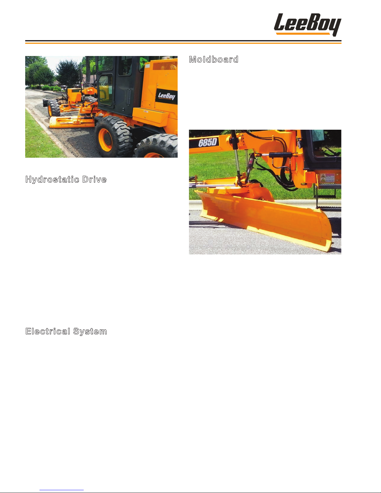
Components
Hydrostatic Drive
This grader is powered by a diesel engine with dualrange, hydrostatic transmission system that propels
the machine forward or reverse at varying speeds with
dynamic braking action. Components of the hydrostatic
drive system include a hydrostatic traction pump,
variable-speed hydraulic motor, two-speed tandem axle,
rear axle carrier assembly and gear drive. A two-speed
transfer case mounted between the drive motor and
rear axle carrier provides high and low gear selection.
The rear axle carrier assembly converts input rotation to
axle shaft output rotation to drive the wheels.
The function and steering pump is mounted on the rear
of the traction pump and driven by the traction pump
output shaft. This provides hydraulic pressure and ow
to operate all the hydraulic cylinders that controls the
steering cylinder and other grader functions.
Electrical System
The electrical system is powered by two 12-volt
batteries, wired in parallel and mounted in a battery
compartment on the frame. Each battery produces
800 cold cranking amperes (CCA) for a total of 1600
CCA. An engine-mounted alternator with 135 amperes
of charging capacity keeps the batteries charged during
normal operation.
Moldboard
The moldboard is a major component of the 685D Motor
Grader. This adjustable, hydraulically-controlled blade
is mounted between the front and rear wheels that can
cut, move and spread materials to grade requirements.
The moldboard blade is mounted under the turntable
circle that can be hydraulically rotated right and left.
The moldboard height is controlled by two hydraulic
cylinders mounted to ball joints at a turntable.
The blade can be aggressively angled perpendicular
to the line of travel or parallel to the direction of travel.
The blade’s curved shape allows material to roll more
freely along the blade. The moldboard can be moved
forward and also shifts three (3) feet (.9 meters) left or
right. It can tilt side-to-side and front-to-rear, rotate
64 degrees, and features oat controls that can cut 1.2
feet (.355 meter) below grade. This versatility allows
extreme moldboard positioning to meet a variety of road
construction and maintenance needs, including easier
bank sloping and ditch cutting.
LeeBoy 685D Motor Grader3-4
Page 43
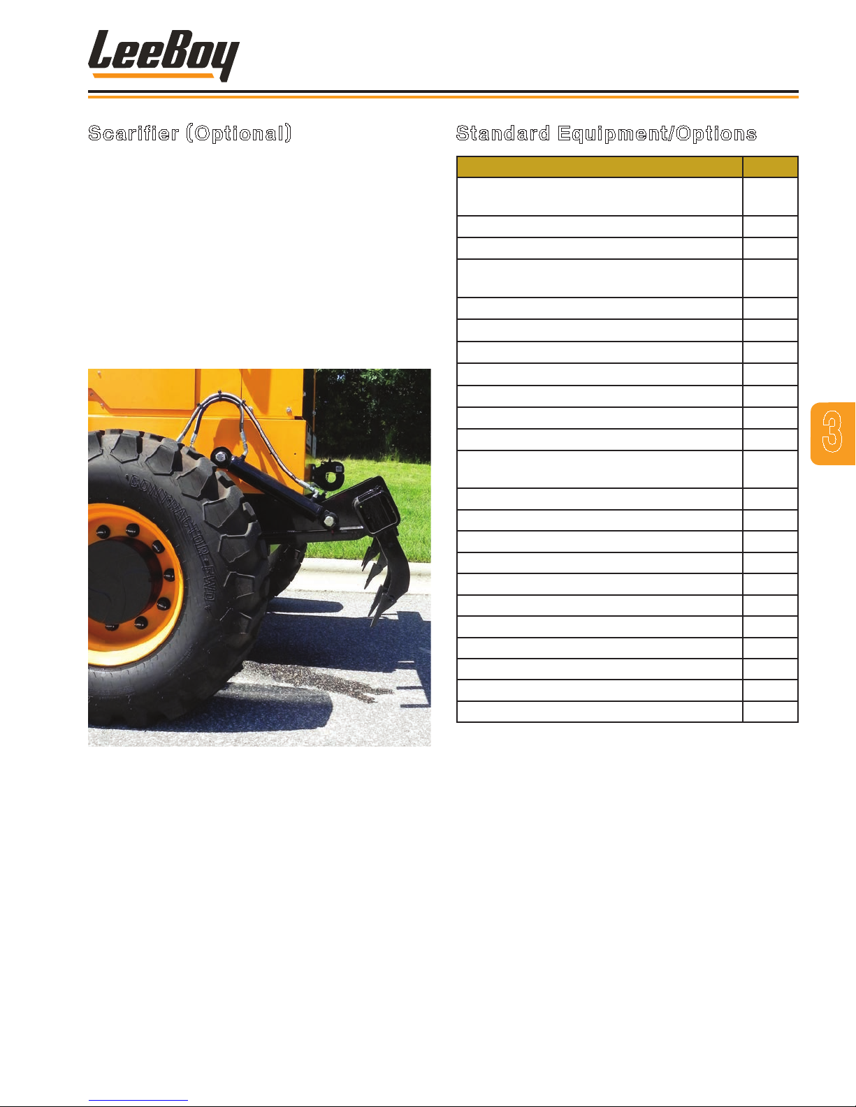
Components
Scarifier (Optional)
The scarier, or ripper, is a mechanism with large teeth
mounted on shanks for penetrating and loosening earth,
gravel, asphalt and similar surfaces to shallow depths.
This attachment is used to break up material too hard
for the moldboard blade to cut, such as a surface
preparation device for ripping asphalt or breaking up
packed soil for construction site preparation, digging
and even landscaping purposes.
Hydraulically raised and lowered, the scarier has ve
replaceable teeth (with space for a total of nine teeth if
needed) for penetrating the grading surface. The tooth
supports are adjustable and secured with pin locks.
Standard Equipment/Options
Component
Sliding Moldboard: 11-Foot (3.3 m)
(Includes Tilt and Float)
Articulated Frame
Safety Beacon and Work Light Package
Hydrostatic Traction Drive with Secondary
Brakes, 2-Speed Tandem Axle
Cushioned, Adjustable Suspension Seat
Anti-Vandalism Package
Heavy-Duty Rear Hitch
Canopy with ROPS/FOPS
Exterior Side Mirrors
Circle Turn Cushion Valve
Cab Version (Includes Heat) Option
Cab Options: A/C, Defrost Fan, Rear Window
Wiper/Washer, Radio
Rear Scarier Option
Front Scarier Option
Front Blade 8-Foot (2.4 m) Option
Front Blade-Mounted, Flip-Down Scarier Option
Front Blade Float Option
12-Foot (3.6 m) Sliding Moldboard Option
AWD (All-Wheel Drive) Option
Secondary Steering Option
Circle Side Shift Option
Cold Weather Engine Package Option
Back-Up Camera Option
v
v
v
v
v
v
v
v
v
v
Option
3
Front or rear scarier options offer the ripping power
to penetrate tough material fast. Choose from front or
rear scarier options (rear shown). The blade-mounted,
ip-down scarier option offers the convenience and
versatility of using the same attachment for plowing
or scarifying operations. This multi-use option also
attaches to the front nose of the grader.
3-5LeeBoy 685D Motor Grader
Page 44
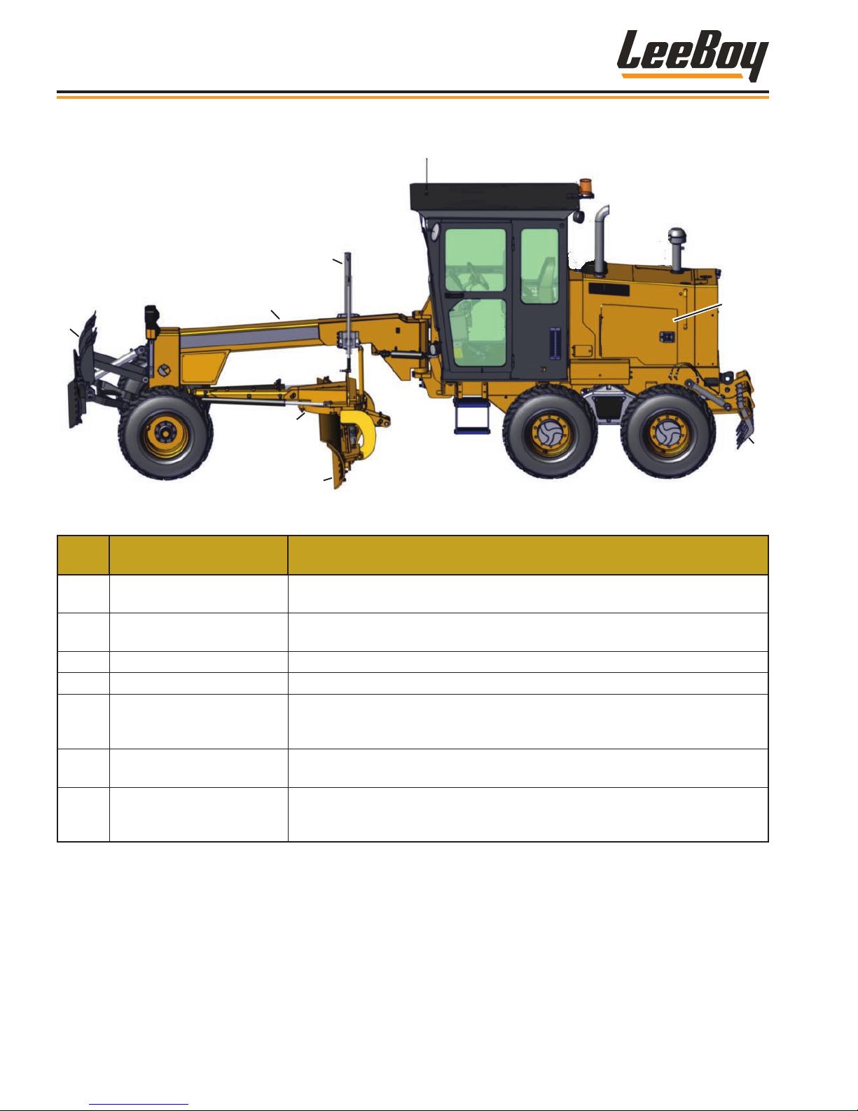
Components
MACHINE OVERVIEW
3
2
1
4
5
Figure 3-1. Machine Overview
ITEM
NO.
1 Front Attachment Mount
2 Front Boom
3 Lift Cylinders Cylinders lift and lower moldboard blade.
4 Turntable Rotates the moldboard left and right.
5 Moldboard
6 Engine Access Panel
7 Rear Scarier (Option)
CONTROL NAME FUNCTION
Optional attachments can be mounted to the attachment plate on the nose of
the grader, including an 8-foot blade or scarier..
The front part of the grader that pivots. The moldboard and optional
attachments are mounted onto the boom.
The moldboard blade is used for grading and smoothing surfaces. Also used
for ditch digging. Mounted under the boom, supported by a drawbar and
turntable.
Lockable access doors on both sides of the machine for easy access to
engine and other components.
Used for penetrating and loosening earth, gravel, asphalt and similar surfaces. Includes nine (9) replaceable teeth mounted on adjustable shanks and
secured with pin locks..
6
7
LeeBoy 685D Motor Grader3-6
Page 45
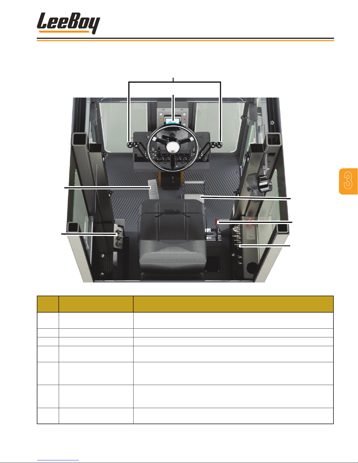
OPERATOR STATION
1
Components
2
3
4
Figure 3-2. Operator Station
ITEM
NO.
1 Steering Column Controls
2 PV485 Digital Controller Displays engine operating parameters, warnings and alerts.
3 Foot Brake Press on the foot brake to stop the grader.
4 Heat/AC Controls (Option)
5
6 Throttle
7 Main Control Panel
CONTROL NAME FUNCTION
Contains steering wheel, component indicator lights, and grader work
function levers.
If equipped with the cab option, this additional option contains controls for
the heat and air conditioner.
FNR (Forward/Neutral/
Reverse) Pedal
Step on the front part of the pedal to move forward; step on the rear part of
the pedal to move in reverse. The center position is NEUTRAL. The FNR
pedal must be in the neutral (center) position to start the engine.
Use to increase and decrease engine speed (RPMs) when in gear (low or
high gear). Push lever forward to increase speed. Push lever rearward to
decrease speed.
Contains numerous machine component controls, including the ignition
switch, lights, park brake, gears, fan, and wipers.
3
5
6
7
3-7LeeBoy 685D Motor Grader
Page 46
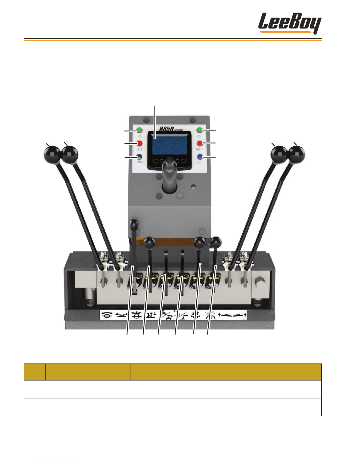
1
12
13
14
15
Components
STEERING COLUMN CONTROLS
Grader operations involve using levers on the steering control panel. When levers are released from the forward or
back position, they return to the neutral center position (except the oat position on the moldboard), suspending the
function or component movement.
2
8
9
3
4
5
6
10
11
7
ITEM
NO.
1 PV485 Digital Controller Displays engine operating parameters, warnings and alerts.
2 Left Turn Signal Indicator Light Blinks when the left turn signal is engaged.
3 Brake Failure Warning Light Illuminates when there is low service brake pressure.
4 All Wheel Drive (AWD) OPTION If equipped with this option, illuminates when AWD is engaged.
CONTROL NAME FUNCTION
16
17
Figure 3-3. Steering Column Controls
LeeBoy 685D Motor Grader3-8
Page 47

Components
ITEM
NO.
5
6 High Gear Indicator Light Illuminates when operating in high gear.
7 High Beam Indicator Light Illuminates when the headlights are switched to high beam.
8 Moldboard Blade Angle Lever Rotates moldboard. Pull lever to rotate left; push lever to rotate right.
9 Moldboard Slide Lever
10 Moldboard Lift Lever (Left)
11 Moldboard Lift Lever (Right)
12 Circle Side Shift (Option)
13
14 Wheel Lean Lever
15 Moldboard Tilt Lever
16 Rear Scarier Lever (Option) Raises/lowers rear attachment. Pull lever to raise; push lever to lower.
17 Articulate Lever
CONTROL NAME FUNCTION
Right Turn Signal Indicator
Light
Front Attachment Lever
(Option)
Blinks when the right turn signal is engaged.
Shifts moldboard left or right. Pull lever to shift moldboard left; push lever
to shift moldboard right.
Raises/lowers left moldboard edge. Pull lever to raise left edge; push
lever to lower left edge. Continue to push lever forward into oat detent.
Push or pull both the left and right moldboard lift levers to raise and lower
the entire moldboard.
Raises/lowers right moldboard edge. Pull lever to raise right edge; push
lever to lower right edge. Continue to push lever forward into oat detent.
Push or pull both the left and right moldboard lift levers to raise and lower
the entire moldboard.
Rotates drawbar left or right. Pull lever to shift drawbar left; push lever
to shift drawbar right. (This lever is nonfunctional if not equipped with
option.)
Raises/lowers optional front attachments. Pull lever to raise, push lever
to lower. (This lever is nonfunctional if not equipped with option.)
Tilts the front wheels left or right. Push lever forward to tilt tires left; pull
lever to tilt tires right.
Tilts moldboard. Pull lever to tilt top of the moldboard backward. Push
lever to tilt top of moldboard forward.
Rotates front “boom” portion of the grader. Pull lever to rotate boom right;
push lever to rotate boom left.
NOTE: The articulation angle can affect the stability of the
machine. Efcient and safe articulation requires skill and
experience to take advantage of its full capabilities.
3
3-9LeeBoy 685D Motor Grader
Page 48
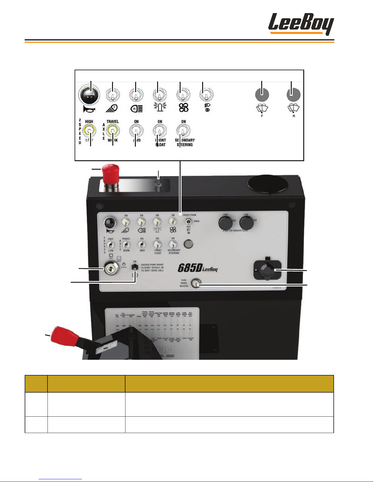
11
Components
MAIN CONTROL PANEL
4
12
1
5 6
13
14
7 8
15
2
16
9
10
3
17
18
21
ITEM
NO.
1 (Emergency) E-Stop
2 Headlight High/Low Beam
CONTROL NAME FUNCTION
19
20
Figure 3-4. Main Control Panel
Immediately stops the engine and all electronic functions. Turn clockwise to
release the emergency stop. If machine is moving, the park brake will apply
and the grader will stop rapidly.
Use this switch to select HIGH or LOW beam when the headlights are on.
Turn the switch up for HIGH BEAM and down for LOW BEAM.
LeeBoy 685D Motor Grader3-10
Page 49

Components
ITEM
NO.
3 Cupholder A convenient holder for beverages.
4 Horn Press this button to sound the horn.
5 Front work lights
6 Rear Lights
7 Beacon Light
8 Fan
9 Headlights Hi/Low Beam Turn the switch UP for high beam; turn the switch DOWN to dim lights.
10
11 Rear Wiper/Washer
12 2-Speed High/Low
13 Axle Travel/Work
14
15 Front Blade Float (Option) Turn switch up to turn on the front blade oat.
16 Secondary Steering Turn switch up to activate secondary power steering.
17 Ignition
18 Park Brake
CONTROL NAME FUNCTION
Turns the front work lights ON and OFF. Turn the switch up to turn ON or
down to turn OFF the front work lights.
Turns the rear lights ON and OFF. Turn the switch up to turn ON or down to
turn OFF the rear lights. The center position is OFF.
Turns the beacon light ON and OFF. Turn the switch up to turn beacon light
ON or down to turn it OFF.
Turns the fan ON and OFF. Turn the switch up to turn fan ON or down to turn
it OFF.
Front Windshield Wiper/
Washer
All-Wheel Drive (AWD)
(Option)
Turns the front windshield wiper ON and OFF. Rotate switch clockwise one
position for low-speed wiper or two positions for high-speed wiper. Rotate
fully counterclockwise to turn off wiper. Push button to spray washer.
Turns the rear wiper ON and OFF. Rotate switch clockwise one position
for low-speed wiper or two positions for high-speed wiper. Rotate fully
counterclockwise to turn off wiper. Push button to spray washer.
Turn switch up to place rear axle gearbox into HIGH gear, used when
traveling to and from job sites. Turn switch down to place rear axle gear box
into LOW gear, used when grading. You must come to a complete STOP
with the FNR pedal in neutral and apply the park brake to shift gears.
Turn the switch up to select TRAVEL speed. Turn the switch down to
select WORK speed. Work speed maintains the hydrostatic drive motor
at maximum torque and a constant speed (with the ability to increase or
decrease speed using the FNR pedal). Travel speed allows the grader
to travel at a higher speed when maximum torque isn’t needed, but
automatically slows when more torque is needed.
If equipped with this option, turn the switch up to turn ON the AWD feature.
Turn the switch down to disengage AWD.
Starts and stops engine. The park brake must be engaged and the FNR
pedal in the neutral (center) position to start the engine.
Engages and disengages the park brake. Push the switch up to engage the
park brake. Push the switch down to disengage the park brake. The park
brake must be applied to start the engine and to shift axle between HIGH and
LOW modes.
3
19 12-Volt Outlet An outlet socket that can provide power for external devices.
20 Fuse Panel Access
21 Throttle
NOTE: Always engage the park brake when the machine is parked.
Provides easy access to the fuse panel. Locks and unlocks to prevent
vandalism.
Use to increase and decrease engine speed (RPMs) when in gear (low or
high gear). Push lever forward to increase speed. Push lever rearward to
decrease speed.
3-11LeeBoy 685D Motor Grader
Page 50
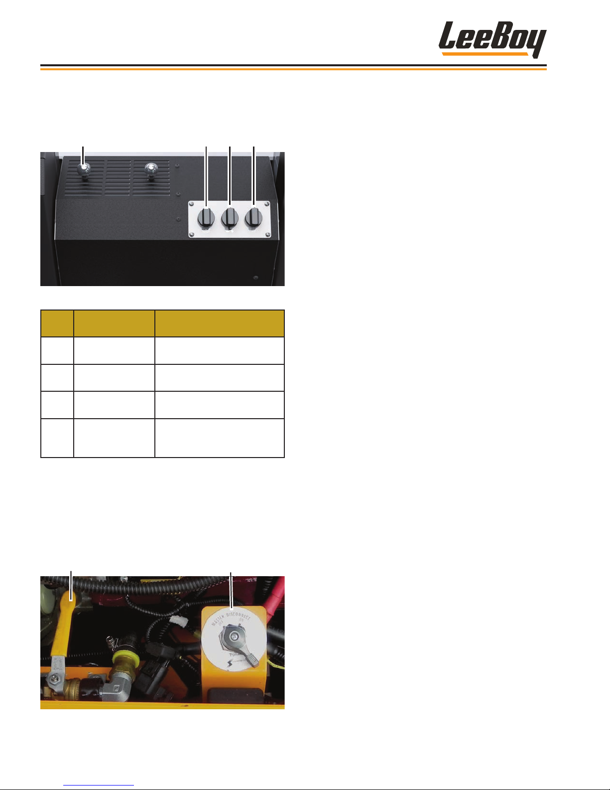
1 2 3 4
Heat Valve
Components
HEAT AND AIR CONDITIONING
(CAB OPTION)
Figure 3-5. Heat and Air Conditioning Controls
Item
No.
• Before turning on heat for the rst time each
winter, open the heat valve beside the master
battery switch located inside the left engine panel
by turning the lever clockwise.
• At the end of winter, shut off the valve by turning
the lever counterclockwise (perpendicular to the
hose).
COMPONENT FUNCTION
1 Vent Knobs
2 Heat
3 Fan
4 Air Conditioning
Opens and closes
recirculation vents.
Adjusts temperature and
turns heat on and off.
Controls blower fan for heat
and air conditioning.
Adjusts temperature and
turns air conditioning on
and off.
Master Battery Switch
Figure 3-6. Heat Valve in the Open Position
LeeBoy 685D Motor Grader3-12
Page 51
Section 4
OPERATION
Operation . . . . . . . . . . . . . . . . . . . . . . . . . . . . . . . . . . 4-1
General Information . . . . . . . . . . . . . . . . . . . . . . . . . . . . 4-3
Receiving the Machine . . . . . . . . . . . . . . . . . . . . . . . . 4-3
Initial and Daily Inspection . . . . . . . . . . . . . . . . . . . . . . 4-3
Start-Up Procedure . . . . . . . . . . . . . . . . . . . . . . . . . . . . 4-4
Brake Check . . . . . . . . . . . . . . . . . . . . . . . . . . . . 4-4
Starting the Engine . . . . . . . . . . . . . . . . . . . . . . . . . . 4-4
Cold Weather Starting . . . . . . . . . . . . . . . . . . . . . . . . 4-5
Stopping the Engine . . . . . . . . . . . . . . . . . . . . . . . . . 4-5
Emergency Stop Button . . . . . . . . . . . . . . . . . . . . . . . 4-5
Regeneration (REGEN) . . . . . . . . . . . . . . . . . . . . . . . . . . . 4-6
Diesel Exhaust Fluid (DEF) After-Treatment System . . . . . . . . . 4-6
PV485 Digital Display . . . . . . . . . . . . . . . . . . . . . . . . . . . 4-7
Gauge Screen . . . . . . . . . . . . . . . . . . . . . . . . . . . . 4-8
Main Menu Screen . . . . . . . . . . . . . . . . . . . . . . . . . . 4-10
Diagnostics . . . . . . . . . . . . . . . . . . . . . . . . . . . . . 4-11
Page
4
System Info . . . . . . . . . . . . . . . . . . . . . . . . . . . . .4-12
User Settings . . . . . . . . . . . . . . . . . . . . . . . . . . . .4-12
Tier 4F . . . . . . . . . . . . . . . . . . . . . . . . . . . . . . . . 4-14
Regen Request . . . . . . . . . . . . . . . . . . . . . . . . . . . 4-15
Driving the Grader . . . . . . . . . . . . . . . . . . . . . . . . . . . . . 4-16
Regen Inhibit . . . . . . . . . . . . . . . . . . . . . . . . . . . . . 4-16
Adjust Seat . . . . . . . . . . . . . . . . . . . . . . . . . . . . . 4-17
Adjust Steering Console . . . . . . . . . . . . . . . . . . . . . . . 4-18
Axle Travel/Work . . . . . . . . . . . . . . . . . . . . . . . . . . . 4-18
2-Speed High/Low . . . . . . . . . . . . . . . . . . . . . . . . . . 4-18
Throttle . . . . . . . . . . . . . . . . . . . . . . . . . . . . . . .4-18
Directional Control . . . . . . . . . . . . . . . . . . . . . . . . . . 4-19
Braking . . . . . . . . . . . . . . . . . . . . . . . . . . . . . . .4-19
Steering . . . . . . . . . . . . . . . . . . . . . . . . . . . . . . . 4-20
LeeBoy 685D Motor Grader
4-1
Page 52

Operation
Articulation . . . . . . . . . . . . . . . . . . . . . . . . . . . . . . 4-20
Front Wheel Lean . . . . . . . . . . . . . . . . . . . . . . . . . . 4-21
Motor Grader Terms . . . . . . . . . . . . . . . . . . . . . . . . . . . . 4-22
Moldboard . . . . . . . . . . . . . . . . . . . . . . . . . . . . . . . . . 4-23
Circle Turn Cushion Valve . . . . . . . . . . . . . . . . . . . . . . 4-24
Grader Attachments . . . . . . . . . . . . . . . . . . . . . . . . . . . . 4-25
Mounting Front Attachments . . . . . . . . . . . . . . . . . . . . . 4-25
Operating Front Attachments . . . . . . . . . . . . . . . . . . . .4-26
Front Blade Float. . . . . . . . . . . . . . . . . . . . . . . . . . . 4-26
Scariers . . . . . . . . . . . . . . . . . . . . . . . . . . . . . .4-27
Operating a Scarier . . . . . . . . . . . . . . . . . . . . . . . . . 4-28
Replacing Scarier Teeth . . . . . . . . . . . . . . . . . . . . . .4-28
Operating Techniques . . . . . . . . . . . . . . . . . . . . . . . . . . . 4-29
Grading Tips . . . . . . . . . . . . . . . . . . . . . . . . . . . . . 4-29
Grading Around Objects . . . . . . . . . . . . . . . . . . . . . . . 4-30
Spreading and Leveling . . . . . . . . . . . . . . . . . . . . . . . 4-31
Slope Work . . . . . . . . . . . . . . . . . . . . . . . . . . . . . 4-32
Grading an “S” Curve Shoulder . . . . . . . . . . . . . . . . . . . .4-33
Road Maintenance . . . . . . . . . . . . . . . . . . . . . . . . . . . . . 4-33
Gravel and Dirt Roads . . . . . . . . . . . . . . . . . . . . . . . . 4-34
Crowning the Road . . . . . . . . . . . . . . . . . . . . . . . . .4-35
Ditch Work . . . . . . . . . . . . . . . . . . . . . . . . . . . . . . 4-35
Cul-De-Sacs . . . . . . . . . . . . . . . . . . . . . . . . . . . . . 4-36
Transport . . . . . . . . . . . . . . . . . . . . . . . . . . . . . . . . .4-37
Loading . . . . . . . . . . . . . . . . . . . . . . . . . . . . . . . 4-37
Unloading . . . . . . . . . . . . . . . . . . . . . . . . . . . . . . 4-38
Tie-Down Procedure . . . . . . . . . . . . . . . . . . . . . . . . . 4-38
Towing . . . . . . . . . . . . . . . . . . . . . . . . . . . . . . . . . . . 4-38
Options . . . . . . . . . . . . . . . . . . . . . . . . . . . . . . . . . .4-39
Cab Option . . . . . . . . . . . . . . . . . . . . . . . . . . . . .4-39
Sliding Moldboard . . . . . . . . . . . . . . . . . . . . . . . . . . 4-40
Circle Side Shift . . . . . . . . . . . . . . . . . . . . . . . . . . . 4-40
Secondary Steering . . . . . . . . . . . . . . . . . . . . . . . . . 4-40
All-Wheel Drive (AWD) . . . . . . . . . . . . . . . . . . . . . . . . 4-41
Cold Weather Engine Package . . . . . . . . . . . . . . . . . . . . 4-41
Reverse Camera System . . . . . . . . . . . . . . . . . . . . . . . 4-41
LeeBoy 685D Motor Grader4-2
Page 53
Operation
GENERAL INFORMATION
The LeeBoy 685D Motor Grader is a hydrostatic,
articulating grader designed with the functionality of
a larger grader but more compact. The 685D model
has the versatility for ne grading, spreading base
materials, ditch and shoulder work, medium cutting,
general construction, shaping, bank sloping, , and even
snow removal. The 685D is excellent for driveways,
parking lots, landscaping and road/runway maintenance
projects as this smaller grader is very maneuverable
and easier to transport than a larger machine.
This section offers information to help you understand
how to operate this grader and its components and
attachments, along with basic grading techniques. Pay
particular attention to safety warnings in Section 1 and
throughout this manual.
Ensure operators are properly
licensed if required in your location.
Use only Ultra-Low Sulfur Diesel
(ULSD) with a maximum sulfur content of 15
ppm or less in this machine. This is a regulatory
requirement. Failure to do so will result in damage to
the engine and after-treatment system within a short
period of time.
Only authorized personnel who are
properly trained should operate this machine. DO
NOT allow others on the operator platform or near
this industrial machine and its heavy equipment at
any time.
DO NOT leave the operator station
unattended while the engine is running.
Keep the steps, hand-hold bars,
operation station and machine components clean
and clear of debris, mud and grease to prevent
falls or other accidents. Be careful mounting and
dismounting the motor grader. Always use the handhold bars and steps. NEVER mount or dismount the
grader while it is moving. DO NOT jump from the
grader at any time.
Receiving the Machine
Although the machine has been checked thoroughly by
the manufacturer, road hazards or other factors during
transport may result in damage. Inspect machine for
any damage during transport. Contact your authorized
dealer immediately if any damage has occurred.
Be sure to check the machine thoroughly upon receipt:
1. Check engine oil. (Page 5-13)
2. Check hydraulic uid level. (Page 5-25)
3. Check DEF tank uid level. (Page 5-17)
4. Check machine hoses for any damage or leaks.
5. Rotate the beacon light bracket from its shipping
position to its operating position. Ensure the
bracket “clicks” into position.
6. Inspect machine for any damage during transport.
Contact your authorized dealer immediately if any
damage has occurred in transit.
Initial and Daily Inspection
The following inspections are essential and should be
performed before starting the machine. Visually inspect
the unit to check its general condition. Continue with a
check of the systems and components shown in Table
4-1 below:
Table 4-1. Initial and Daily Inspection
INSPECT PROCEDURE
Engine Oil
Level
Fuel Tank
Hydraulic
Tank
DEF Tank
Radiator
Brake
Battery
Air Cleaner
Drain Plugs Make sure plugs are inserted and tight.
Engine Belt Check for wear or damage.
Grease
Fittings
Maintain oil level between ADD and FULL
marks on dipstick.
Check for adequate fuel supply. Fill if
needed. Always ll tank at end of the day to
prevent condensation in the tank.
Check the tank for oil level and leaks.
Check the DEF tank level and rell if needed.
Check coolant level.
Always perform a pre-start brake check
before operating using the procedure shown
on Page 4-4.
Ensure all cables are tight and clean. Check
for corrosion on the battery terminals.
Check the air lter element and connections.
Air cleaner has both a primary and
secondary lter.
Ensure ttings are greased and in good
working order.
4
LeeBoy 685D Motor Grader 4-3
Page 54
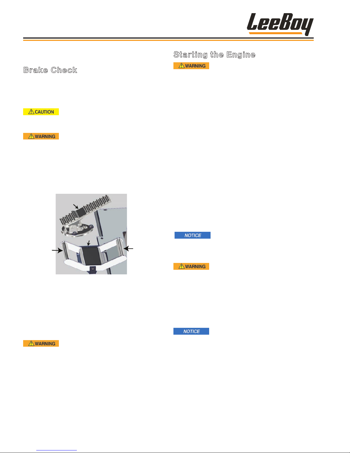
Operation
START-UP PROCEDURE
Brake Check
A Neutral Start feature has been installed for safety.
The grader will not start unless the FNR pedal is in the
neutral position. It is recommended that operators
always check the brake before operating.
Verify there are no people, obstacles
or other equipment in the machine’s path before
starting the engine.
Be sure the park brake is engaged
and the FNR pedal is in the neutral position before
starting the engine. DO NOT put your foot on the
FNR pedal when starting.
To check that the park brake is functioning properly:
1. Engage the park brake. (Figure 4-2)
2. Step on the foot brake pedal. (Figure 4-1)
Foot Brake
GENTLY
Press for
Forward
Press for
Reverse
FNR
Starting the Engine
ALWAYS fasten your seat belt and
adjust steering console, seat and mirrors BEFORE
starting the engine.
To start the 685D Motor Grader:
1. Ensure the park brake is engaged. (Figure 4-2)
2. Fasten seat belt, adjust steering console, seat
position and mirrors.
3. Place the FNR pedal into the NEUTRAL position.
(Figure 4-1)
4. Ensure the throttle is in the idle position (completely
rearward). Check control panel gauges for proper
readings.
5. Insert key into the ignition and turn clockwise to the
ON position. (Figure 4-2)
• The PV485 digital controller on the steering
control console (described on the following
pages) will “boot” for a few seconds when
starting the engine. A “Wait to Start” banner will
appear for a few seconds while booting. AFTER
the Wait to Start light disappears, turn key to the
START position to crank engine.
DO NOT hold the starter longer than
10 - 15 seconds. If the engine does not start, allow
the starter to cool two or three minutes between
attempts to prevent damage to the starter.
Figure 4-1. FNR Pedal
3. Turn the ignition key to the START position. The
engine should not start unless the FNR pedal is in
NEUTRAL (center position).
• If the engine starts with the FNR pedal in
either FORWARD or REVERSE, contact your
authorized dealer immediately for service. DO
NOT drive the grader until repaired.
The FNR pedal is very sensitive. Use
only a little pressure on the pedal when moving
in forward or reverse to prevent lunging. DO NOT
engage FNR pedal before releasing park brake.
The engine is equipped with an
electric heat starting system. Using start additives,
such as ether, is not recommended as it could cause
an explosion resulting in severe injury and/or engine
damage.
6. Check control panel gauges for proper readings.
7. Allow the engine to idle a few minutes before moving
in either direction.
A safety sensor system in the seat
detects whether the operator is properly seated.
The grader will remain in neutral and will not move
forward or reverse, despite movement of the FNR
pedal, if the operator is not seated.
LeeBoy 685D Motor Grader4-4
Page 55
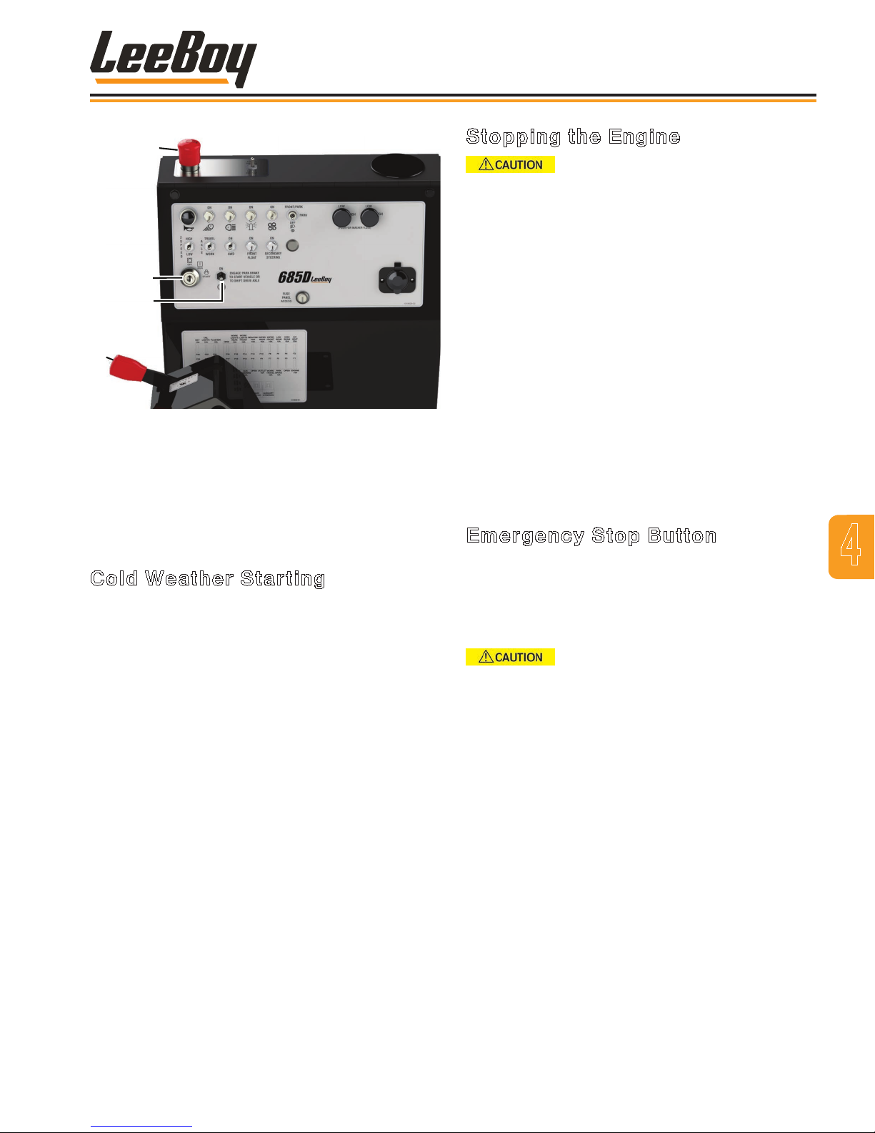
4
Operation
Stopping the Engine
Before leaving the operator station,
place the machine in neutral, lower the moldboard
(and any other attachments) to the ground, and apply
the park brake.
1. Lower all attachments to the ground.
3
2
1
Figure 4-2. Start-Up Controls
1 - Throttle Lever
2 - Park Brake Switch
3 - Ignition Switch
4 - E-Stop Button
Cold Weather Starting
1. Engage the park brake. (Figure 4-2)
2. Insert key into the ignition and turn clockwise to
the START position. (The “Wait to Start” light will
illuminate for a few seconds on the steering control
panel). AFTER the Wait to Start light disappears,
turn key to the ON position to crank engine.
3. Allow the engine to idle about ten minutes before
driving the machine.
2. Apply park brake.
3. Turn ignition key counterclockwise to the OFF
position and remove key.
NOTE: The electrical system will continue to
operate for approximately 20 seconds after
the ignition is turned off. This allows the
engine ECU (Engine Control Unit) to store
critical engine data as it powers down.
NOTE: You may also hear a slight noise for a few
seconds after turning off the engine. This
is the DEF (Diesel Exhaust Fluid) system
automatically purging.
Emergency Stop Button
The purpose of the Emergency Stop Button (E-Stop)
is to shut down the engine and all machine functions in
an emergency situation. This additional safety feature
should only be used if the operator needs to shut down
all machine operations quickly. (Figure 4-2)
ALWAYS wear your seat belt! If you
engage the E-Stop button, the grader will stop very
quickly and could result in serious injury if you are
not wearing seat belt securely.
4
LeeBoy 685D Motor Grader 4-5
Page 56
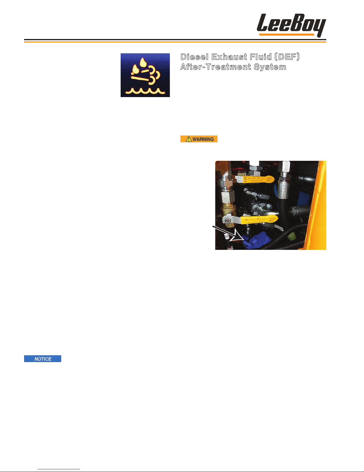
Operation
REGENERATION
(REGEN)
Regeneration is the term given to the
cleaning process where the exhaust
temperature is raised to safely
burn off any soot and undesired combustion gas to
signicantly reduce toxic emissions as required by Tier
4 Final engine standards.
Maintenance is kept at a minimum with a crankcase
ventilation breather that requires no lter element, and
a Cummins Filtration Direct Flow air cleaner that has a
higher dust capacity. It is particularly important that the
operator understand the regeneration process before
operating the grader.
This engine uses Diesel Exhaust Fluid (DEF), (known as
AdBlue® in Europe), a critical element of its Selective
Catalytic Reduction (SCR) after-treatment system.
Alerts and messages illuminate on the PV485 digital
display controller (described in the following pages)
when the DEF tank needs to be lled or the regeneration
process needs to be performed.
When the soot saturation in the exhaust system reaches
a certain level, the onboard engine ECU (Engine
Control Unit) will activate a regeneration cycle. During
normal operation, the regeneration process begins
automatically. This engine requires little to no operator
interaction, but under certain circumstances, the
operator may have to initiate the regeneration process.
The exhaust system cleaning light will illuminate during
regeneration. It is important not to shut off the engine
as the regeneration cycle will fail and could possibly
damage the engine. Once regeneration is complete,
the light will turn off. If the regeneration cycle fails, the
ECU may attempt a second regeneration.
Use only Ultra-Low Sulfur Diesel (ULSD) with a maximum
sulfur content of 15 ppm or less in this machine. Failure
to do so will result in damage to the engine and aftertreatment system within a short period of time.
Modifying or disconnecting any
emission-related component will subject you to
government penalties and void your warranty.
Tampering with emission controls is in violation of
federal law, and can result in serious civil penalties.
Diesel Exhaust Fluid (DEF)
After-Treatment System
The LeeBoy 685D Motor Grader is equipped with a
DEF after treatment system that treats post-combustion
exhaust gases prior to tailpipe emission. This system
allows greater engine power, higher torque and fuel
economy while decreasing exhaust pollution. The
DEF system is an important factor in operating the
machine. Keeping the DEF tank lled is critical to engine
operation. (Figure 4-3)
DO NOT operate the machine with
an empty DEF tank to prevent serious engine and
emission system damage.
DEF Tank
Filler Cap
Figure 4-3. DEF Fluid Tank
If the DEF tank level runs low (below 15 percent) during
operation, a solid yellow DEF warning symbol will
illuminate on the PV485 controller screen. If the level
drops to ve (5) percent, the warning icon ashes yellow.
Engine torque will be reduced 50 percent and engine
speed will be reduced 40 percent after 45 minutes.
If the operator continues to ignore the warning and
the DEF tank is still not relled after an additional 45
minutes, the warning icon will illuminate red and ash
continuously. At this point, there will be no available
torque--the engine will only idle.
In either of these conditions, relling the DEF tank will
restore engine performance.
LeeBoy 685D Motor Grader4-6
Page 57
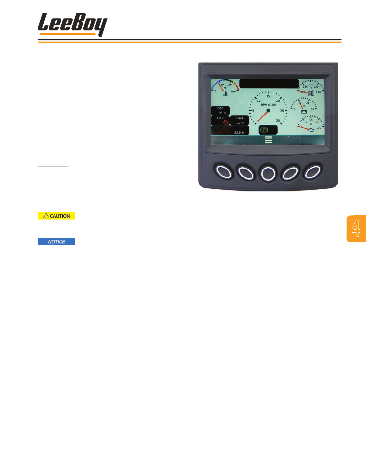
If the DEF tank level has fallen to 0 percent, a STOP
warning symbol will also illuminate and ash red. At this
level, there is no ability for DPF regeneration or DEF
injection into the exhaust system, therefore no ability to
cool the DEF injector as needed. The DEF injector may
now be damaged by heat and require replacement
from your authorized dealer.
DEF Thaw Control Mode: Sensors on the DEF tank
also detect the ambient air temperature within seconds
of starting the engine. If the DEF is frozen, the SCR
system automatically starts the Thaw Control Mode and
turns on the DEF pump, tank and tube heaters. Engine
maximum torque may be limited to protect the DEF
injector.
DEF Purge: The SCR system will automatically purge
DEF after shutting down the engine. You will hear the
pumping noise as the system circulates DEF to cool
the DEF injector, then the pump reverses to return DEF
back to the tank. Always allow this purging process to
nish to prevent damage to the injector and other SCR
components.
Operation
Figure 4-4. PV485 Digital Display Controller
NEVER disconnect battery until the
purge cycle has completed to prevent serious
damage to components in the SCR system.
Be sure the DEF uid in the tank is not
contaminated before relling. Dispose of DEF uid in
accordance with environmental laws.
PV485 DIGITAL DISPLAY
Before driving the LeeBoy 685D Motor Grader, it is
important to be familiar with the PV485 PowerView™
digital controller located on the steering control panel.
This system is a multi-functional display that enables
operators to view standard engine parameters along
with active and stored trouble codes.
• The digital display screen show single or multiple
text descriptions, i.e., engine temperature, voltage,
oil pressure, engine RPMs, and service reminders
or fault conditions. The operator can toggle through
different screens for displaying critical data broadcast
by the electronic engine and transmission Engine
Control Unit (ECU).
• Diagnostic codes with text descriptions of fault
conditions are enhanced by ultra-bright alarm
indicators that illuminate amber or red to alert the
operator of a condition requiring attention.
• An amber warning light illuminates to alert the
operator that a trouble code or service reminder
is being shown on the display.
4
LeeBoy 685D Motor Grader 4-7
• If the red warning light illuminates, the operator
should shut down the machine and promptly
repair the problem to prevent possible damage.
Page 58
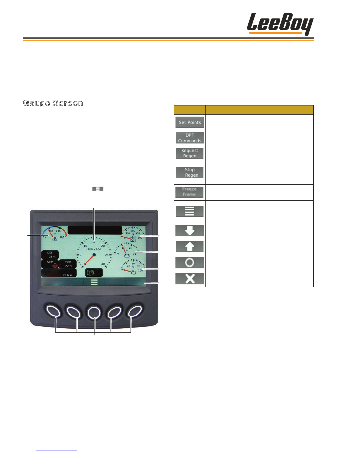
2
3
4
5
6
Operation
When turning the ignition key to the ON position, you
will see a logo with the “Wait to Start” banner along the
bottom of the screen while the system “boots.” DO NOT
start the engine until this message disappears and
the gauge screen appears.
Gauge Screen
The gauge screen is the rst screen to appear on the
PV485 digital controller when starting the engine. This
is the default screen. (Figure 4-5)
Pressing the “soft key” buttons along the bottom of the
controller unit allows the operator to navigate to various
other screens. The banner icons along the bottom of
the screen correspond with these buttons, and change
accordingly when navigating to other screens as
described on the following pages. Table 4-2 shows the
icons that appear on the banner with descriptions.
Pressing the center button ( ) navigates to the Main
Menu screen. (Page 4-10)
Soft Keys (Buttons)
The following table shows icons appearing on the
bottom banner that correspond to the soft key button,
depending upon the screen mode. (Some sources may
not be present on your model.)
Table 4-2. Soft Key Choices
Icon Description
Displays the default speed (RPMs) set
points.
Displays the DPF commands to access
Uninhibit Regen and Inhibit Regen.
Sends message to the ECU to start DPF
regeneration.
Sends message to the ECU to stop DPF
regeneration. (DO NOT use unless
necessary.)
Requests freeze frame data from the
ECU when faults are present.
Navigates to the Main Menu screen
where you can scroll to choose action
items (such as settings and diagnostics).
1
Soft Keys
Figure 4-5. Gauge Screen
1 - Engine Coolant Temperature
2 - Engine Speed/RPMs
3 - Hydraulic Oil Temperature
4 - Battery Voltage
5 - Actual Engine Torque Percentage
Use to scroll down through a list of items.
Use to up scroll through a list of items.
Select: Enters the action item selected.
Deselect: Closes pop-up messages.
6 - Soft Key Banner
LeeBoy 685D Motor Grader4-8
Page 59
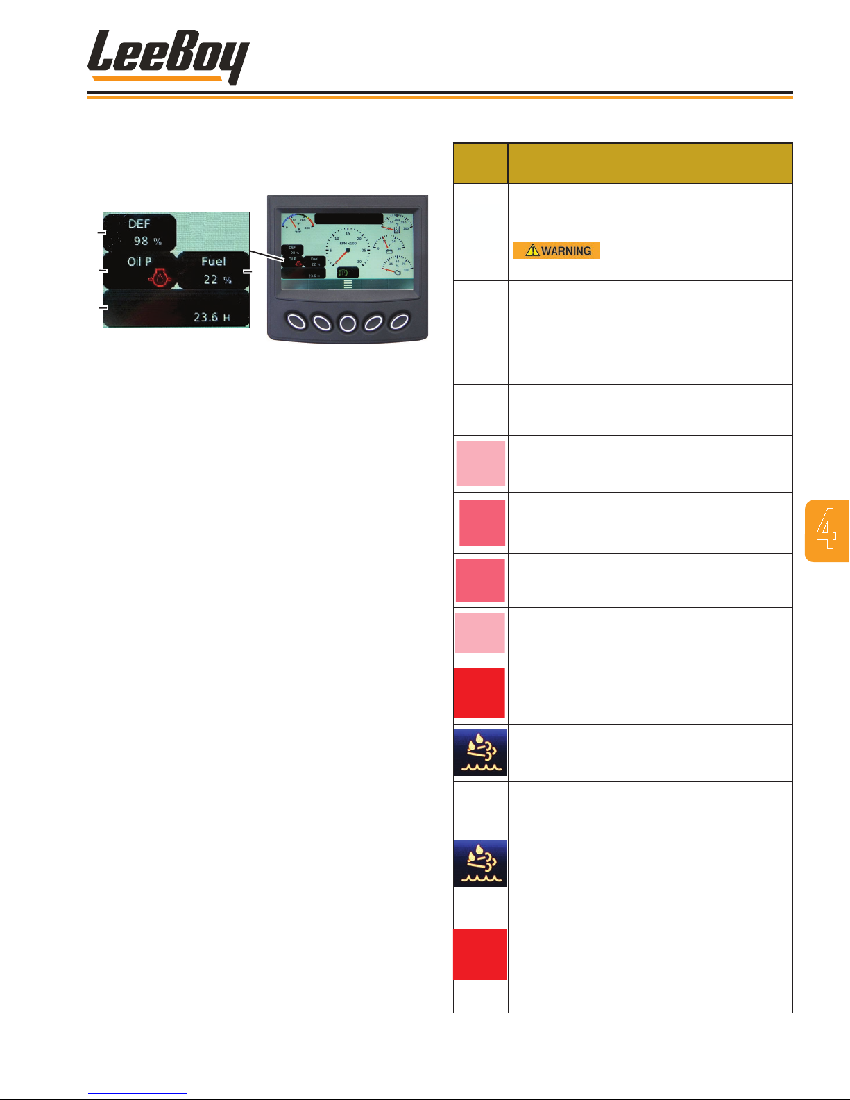
Operation
The soft menu screen also displays engine torque
percentage, DEF tank level, engine oil pressure, total
hours of operation, and fuel level in the lower left
quadrant of the screen. (Figure 4-6)
1
2
3
Figure 4-6. Status Quadrant
1 - DEF Tank Level
2 - Engine Oil Pressure
3 - Engine Total Hours of Operation
4 - Fuel Level
Warning lights will illuminate and fault codes will also
display:
• The engine oil light is normally illuminated green,
but will illuminate red if the hydraulic or engine oil
pressure is too low and display a warning icon on the
screen.
• A warning icon will also display if the hydraulic or
engine oil temperature is too high.
• Other warning and status icons may also illuminate.
(Table 4-3)
4
Status
Icon
Table 4-3. Status Icons
Description
Check Engine. When this lamp is illuminated
yellow, a fault exists within the control
system.
Take action immediately to
correct the fault.
Stop Engine. Illuminates red (and may ash)
when continued operation could result in
damage to the exhaust system. Shut down
the engine and do not operate the machine
until repair has been made. Contact your
authorized dealer if needed.
Park Brake. The park icon displays when
the parking brake is applied.
Alternator. Illuminates when the alternator
isn’t charging properly.
Coolant. Illuminates when the engine is
running too hot.
4
Fuel. Illuminates when the fuel tank is almost
empty.
Hydraulic Oil. Illuminates to warn operator
when the hydraulic oil is too hot.
Refer to Section 5, Troubleshooting, for a complete
list of Fault Codes.
LeeBoy 685D Motor Grader 4-9
Oil Pressure. Illuminates when the oil
pressure is low. A wavy line underneath
indicates the engine oil level is too low.
DEF Tank Level Warning Icon. This lamp
illuminates if the DEF tank level runs low
(below 15 percent). Rell the DEF tank.
DEF Lamp with Check Engine Lamp. The
yellow check engine and DEF tank warning
lamps illuminate if DEF tank is critically low.
Rell the DEF tank. Engine power will be
reduced, but will return when lled.
Diesel Exhaust Fluid (DEF) System
Warning. Indicates a failure of the emission
system or that engine emissions are too
high. The DEF may be contaminated and
need to be replaced, or the system may need
service. Contact your authorized dealer for
assistance if needed.
Page 60
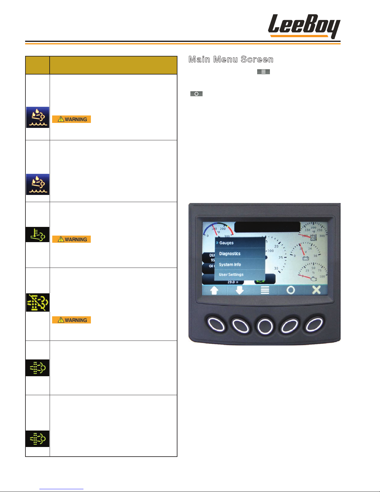
Operation
Status
Icon
Description
Flashing DEF Lamp with Stop Engine
Lamp. Illuminates when the DEF tank is near
zero, further limiting power. Rell DEF tank
immediately to avoid damage! Normal
power will restored when DEF tank is lled.
Insufcient DEF can result
in damage to the DEF injector and other
components.
Flashing DEF Lamp with Red Stop Engine
Lamp. Illuminates when the DEF has read
zero for 30 minutes. Power will be limited to
IDLE. STOP the machine and rell the DEF
tank immediately! If relling the DEF tank
does not turn the lamps off and/or restore
normal engine power, stop operation and
contact your authorized dealer immediately.
High Exhaust System Temperature (HEST)
Lamp. May illuminate when higher than
normal exhaust temperature exists due to
regeneration.
Main Menu Screen
Pressing the Main Menu ( ) soft key navigates to the
Main Menu action items. (Figure 4-7) Scroll through
the list using the UP/DOWN arrow keys, then press the
( ) key when the cursor (>) points to screen you wish
to view to select that screen mode. The Main Menu
choices are listed below and described on the following
pages:
• Gauge (default screen)
• Diagnostics
• System Info
• User Settings
• Tier 4
NOTE: Continue scrolling using the DOWN arrow
key to access the Tier 4F menu action items.
(Page 4-14)
Ensure the exhaust
pipe is not directed at any ammable
or combustible surface if any high
temperature icons illuminate.
DPF Regeneration Set to Inhibit — The
user may choose to inhibit the REGEN
if conditions are too hazardous for high
exhaust temperatures. When this lamp is
illuminated, a REGEN cannot be performed
and soot levels will continue to rise.
Unless hazardous
conditions exist, the REGEN Inhibit switch
and this lamp should remain off.
Exhaust System Cleaning. Illuminates
when the exhaust system is unable to
complete regeneration. As soon as
possible, performed a parked regeneration
procedure. (Pages 4-14 to 4-15) The icon
will ash during regeneration and stop once
regeneration is complete.
Exhaust System Cleaning and Check
Engine Lamps. Indicates a failure of the
emission system because the operator failed
to perform regeneration in a timely manner.
Engine power will be signicantly reduced.
Perform parked regeneration immediately.
Contact your authorized dealer for
assistance if engine power does not return.
Figure 4-7. Main Menu Screen
LeeBoy 685D Motor Grader4-10
Page 61
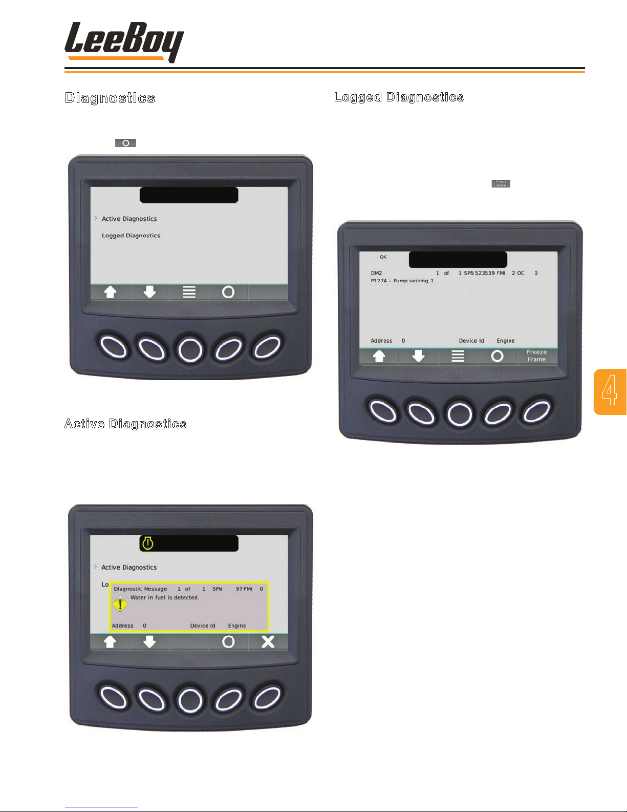
Operation
Diagnostics
Use the UP/DOWN soft keys and stop the cursor (>) for
to view either active or logged diagnostics, then press
the Select ( ) soft key. (Figure 4-8)
Figure 4-8. Diagnostics Screen
Logged Diagnostics
The Logged Diagnostics screen displays nonactive
warnings or faults with the appropriate Suspect
Parameter Number (SPN) and Failure Mode Indicator
(FMI) that are stored in the system. (Figure 4-10) Use
the UP/DOWN soft keys to scroll through list if needed.
NOTE: Select the Freeze Frame ( ) button to
request that frame data from the ECU when
faults are present.
4
Active Diagnostics
The Active Diagnostics screen displays active warnings
or faults with the appropriate Suspect Parameter
Number (SPN) and Failure Mode Indicator (FMI).
(Figure 4-9) Use the UP/DOWN soft keys to scroll
through list if needed.
Figure 4-10. Logged Diagnostics Screen
Figure 4-9. Active Diagnostics Screen
LeeBoy 685D Motor Grader 4-11
Page 62
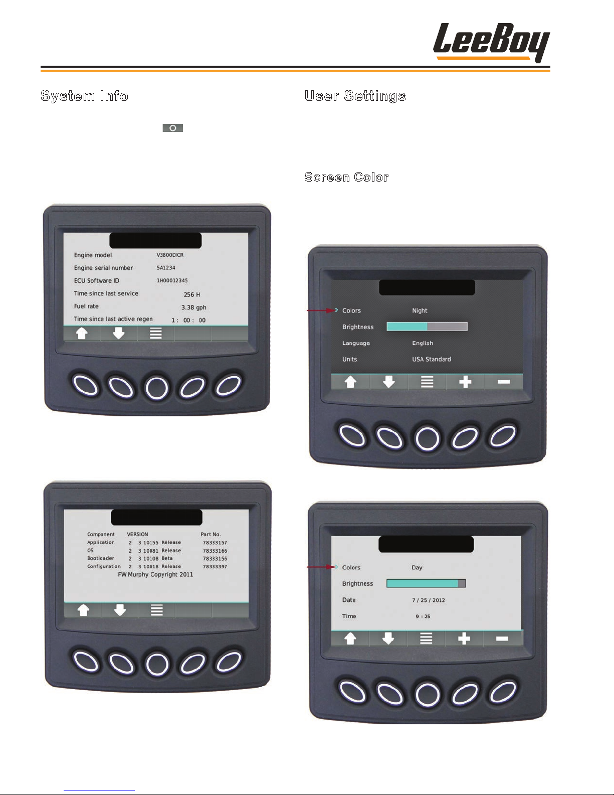
Operation
System Info
Scroll through the Menu list using the UP/DOWN soft
keys, then press the select ( ) soft key when the
cursor (>) points to the desired information. (Figure
4-11) The screen displays the engine model, serial
number, ECU Software ID, fuel rate, and the amount of
time since the last active regeneration process was
performed.
User Settings
These screens displays the following action items:
Screen Color; Brightness; Language; Units; Date and
Time.
Screen Color
Use the UP/DOWN soft keys and stop the cursor (>)
next to the action item Colors. (Figures 4-13 and 4-14)
Set your preference for day or night vision using the +/–
soft keys.
Figure 4-11. System Info Screen
Press the UP/DOWN soft keys to scroll to the screen
with application and conguration information. (Figure
4-12)
Figure 4-12. Application and Conguration
Information Screen
Figure 4-13. Set Night Vision Color Preferences
Screen
Figure 4-14. Set Day Vision Color Preferences
Screen
LeeBoy 685D Motor Grader4-12
Page 63
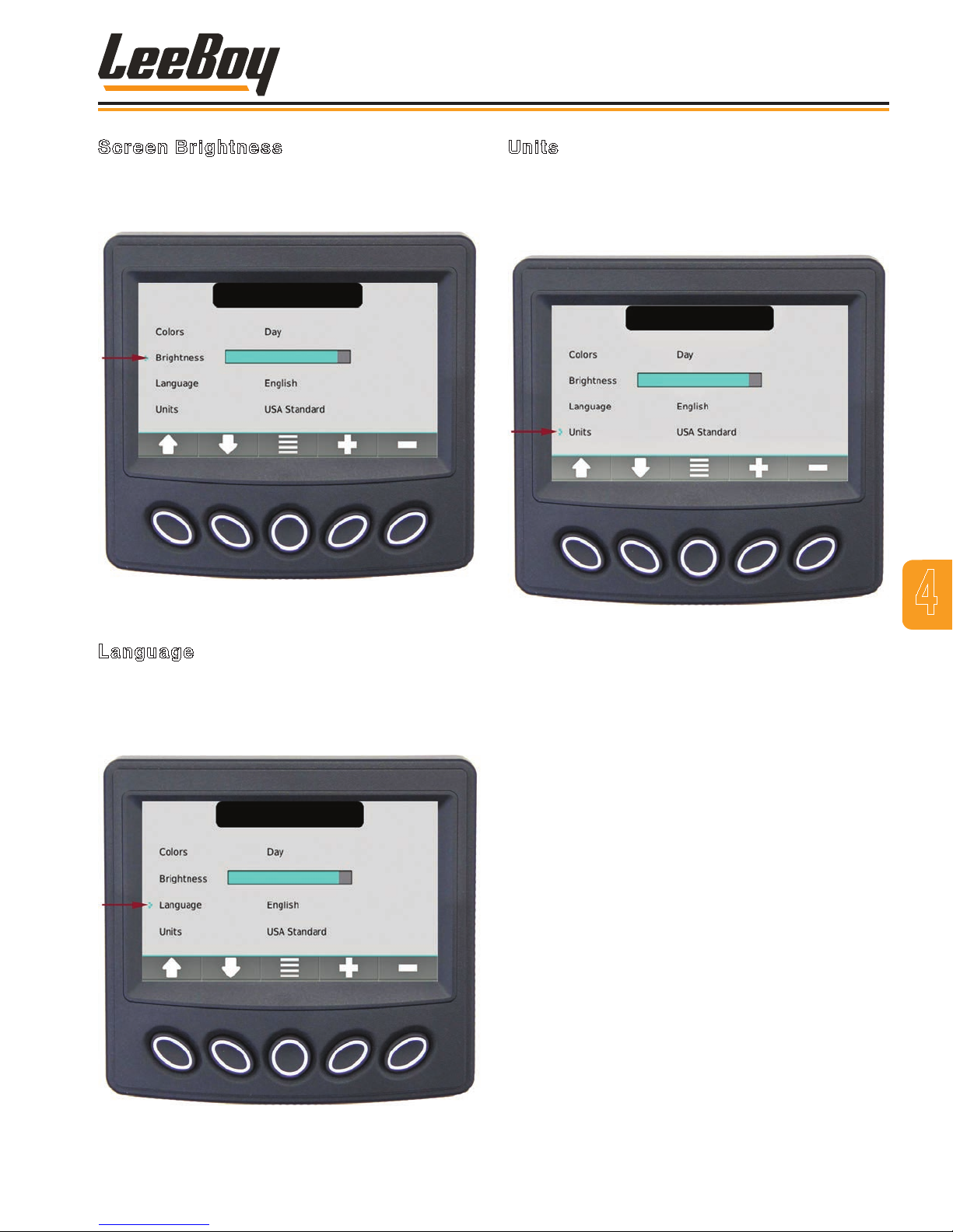
Operation
Screen Brightness
Use the UP/DOWN soft keys and stop the cursor (>)
next to the action item Brightness. (Figure 4-15) Set
the brightness of the backlight by using the +/– soft keys.
Figure 4-15. Set Brightness Of Backlight Screen
Units
Use the UP/DOWN soft keys and stop the cursor (>)
next to the action item Units. (Figure 4-17) Set your unit
preference using the +/– soft keys. (US Standard, Metric
kPa or Metric Bar.)
Figure 4-17. Set Unit Preferences Screen
4
Language
Use the UP/DOWN soft keys and stop the cursor (>)
next to the action item Language. (Figure 4-16) Set
your language preference using the +/– soft keys.
(English, French, German, Spanish, Italian or Japanese)
Figure 4-16. Set Language Preferences Screen
LeeBoy 685D Motor Grader 4-13
Page 64
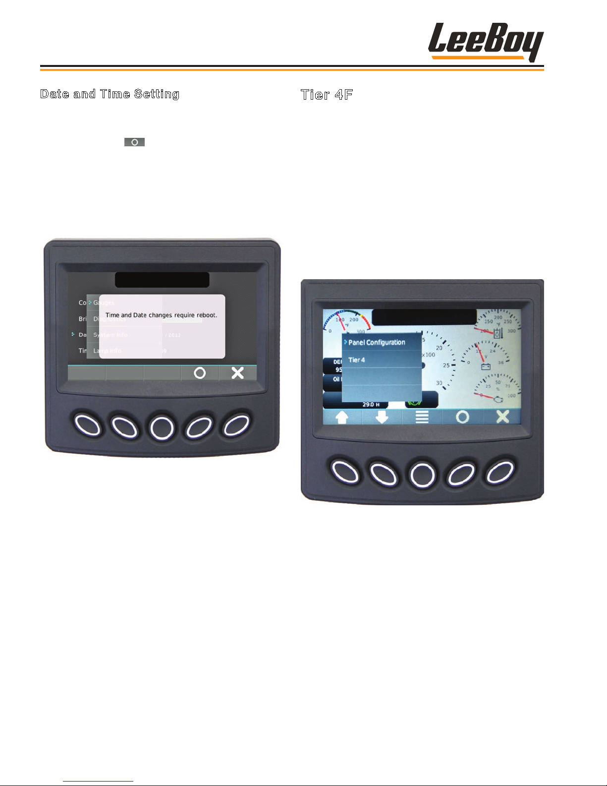
Operation
Date and Time Setting
Use the UP/DOWN soft keys and stop the cursor (>)
next to the action item Date or Time. (Figure 4-18)
• Press the select ( ) soft key to initiate change to
the month value. Use the (+/–) soft keys to increment
or decrement the number.
• Use the DOWN arrow to reach the day value and year
value, using the +/– soft keys to make changes.
NOTE: A reboot is required for changes to the Date
Setting to take effect.
Tier 4F
During normal operation, the regeneration process
begins automatically. If for some reason automatic
regeneration does not proceed, the operator should
navigate to the Tier 4 screen from the Main Menu.
(Figure 4-19) Use the UP/DOWN soft keys and stop the
cursor (>) next to the action item.
The machine should be maintained in an operating
condition so the system can automatically regenerate.
(A complete listing of Fault Codes is shown in
Troubleshooting, Section 5.)
NOTE: Only an authorized technician can access
the Panel Conguration screen for service
purposes.
Figure 4-18. Time Setting Screen
NOTE: Pressing the “X” button closes the pop-up
messages.
Figure 4-19. Tier 4 Navigation
The engine speed will increase during regeneration
and there may be a noticeable sound difference.
It is important not to shut off the engine as the
regeneration cycle will fail and could possibly
damage the engine. Once regeneration is complete,
the engine will return to normal idle speed. If the
regeneration cycle fails, the ECU may attempt a second
regeneration.
LeeBoy 685D Motor Grader4-14
Page 65
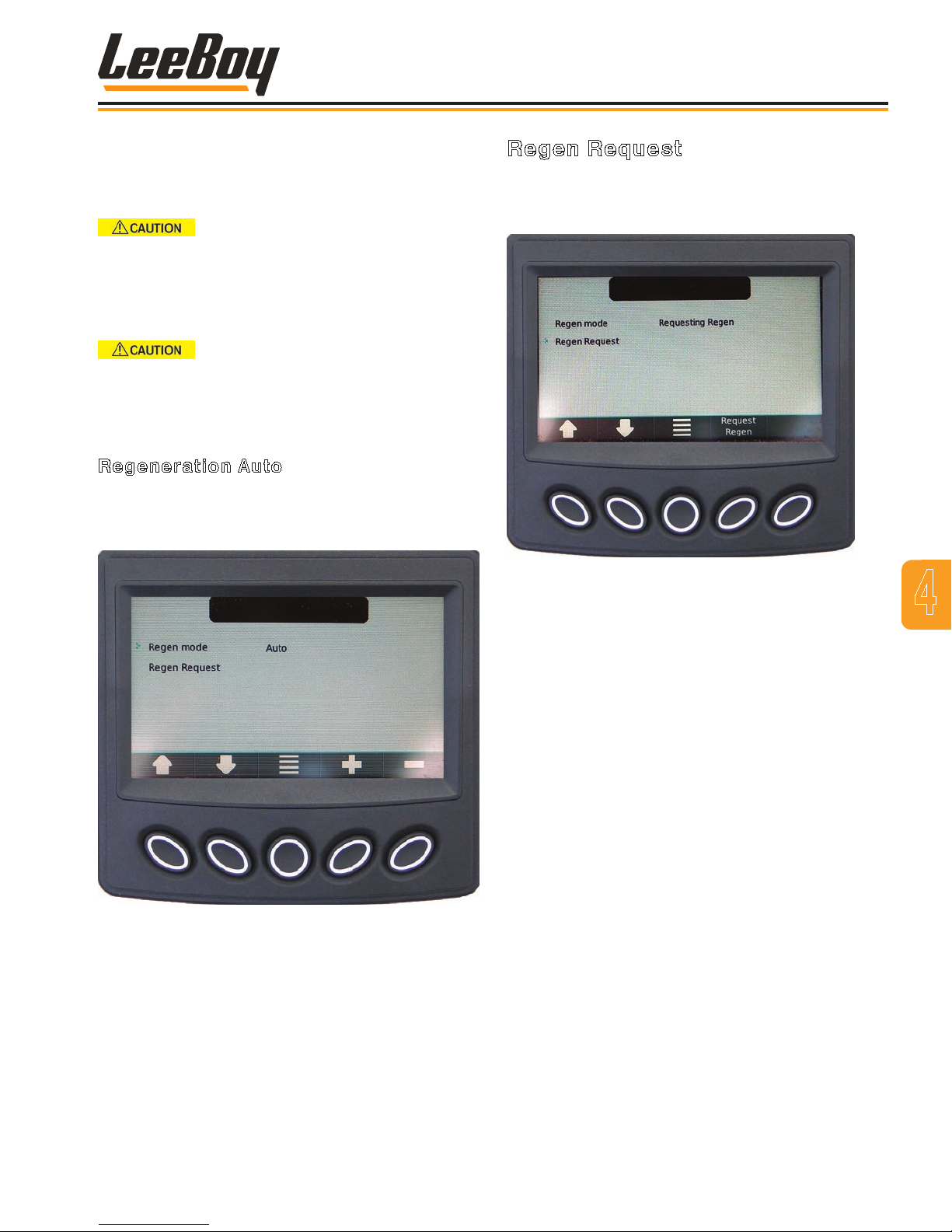
Operation
The HEST Lamp will illuminate and ash during the
regeneration process. (Table 4-3, Page 4-9) When
regeneration is complete, the engine will return to
normal idle speed and the HEST lamp will disappear.
DO NOT TURN OFF THE ENGINE,
ATTEMPT TO OPERATE THE UNIT, CHANGE ENGINE
RPM OR MOVE FROM PARK TO NEUTRAL WHILE
REGENERATION IS OCCURRING. This will abort the
regeneration process and require you to start the
process over.
EXHAUST TEMPERATURES WILL BE
EXTREMELY HIGH. BE SURE EXHAUST WILL NOT
COME INTO CONTACT WITH ANY FLAMMABLE OR
COMBUSTIBLE MATERIALS.
Regeneration Auto
The Regen Auto screen is the default screen
when navigating the Tier 4 as the system is set to
automatically regenerate when needed. (Figure 4-20)
Regen Request
To initiate the regeneration process, use the DOWN soft
key to select Regen Request and follow the procedure
below. (Figure 4-21)
Figure 4-21. Regen Request
Figure 4-20. Regen Auto Screen
BEFORE initiating the regeneration process:
1. Park the machine in a safe location where
the exhaust pipe does not face ammable or
combustible materials.
2. Engage the park brake and place the transmission
in either Park or Neutral.
3. With the engine running at IDLE speed, press the
Request Regen soft key to initiate the regeneration
process. (Figure 4-21) The HEST lamp will
illuminate.
4. Allow the regeneration process to proceed,
monitoring the machine and surrounding area for
safety.
NOTE: If you must stop the regeneration process,
DO NOT turn the engine off while
regeneration is in process. The Request
Regen soft key changes to Cancel Regen
once regeneration begins. Simply push
the (fourth) button under “Cancel Regen”
to communicate with the engine that
regeneration is unwanted or unsafe at this
time. Perform the regeneration process as
soon as possible.
4
LeeBoy 685D Motor Grader 4-15
Page 66
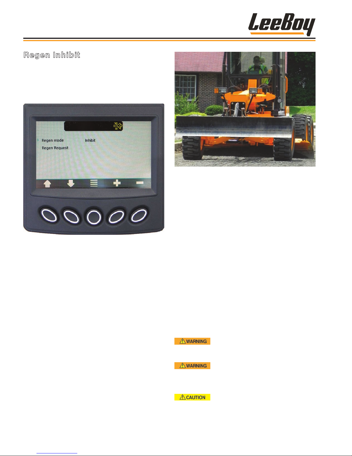
Operation
Regen Inhibit
You can scroll to the Regen Inhibit mode if the
regeneration process is unwanted or unsafe. (Figure
4-22)
Be sure to perform the regeneration process as soon
as possible to prevent engine damage.
Figure 4-23. Driving the 685D Motor Grader
Figure 4-22. Regen Inhibit Screen
NOTE: Continued operation without completing
a parked regeneration can cause engine
damage. If the exhaust soot level builds up
too much, non-warranty factory assistance
from the engine manufacturer is required.
DRIVING THE GRADER
Motor graders can be used for a number of different
tasks in a variety of ways. This type of vehicle handles
differently than other industrial machines, with numerous
capabilities and techniques that require skill and
experience. Fine, delicate jobs must be done slowly,
while others such as snow removal or knocking rocks
off a gravel road can be done faster. Keeping control
of the grader during the entire operation is key for job
quality and overall safety.
The 685D Motor Grader offers several features to
maximize the machine’s potential and efciency while
grading. Regardless of your skill level, it is important
to read this manual thoroughly to understand the
machine’s performance. Pay particular attention to
Section 1, Safety and safety warnings contained
throughout this manual. Know and understand the
various controls and functions before operating the
machine.
NEVER allow bystanders near the
machine while operating. Never allow anyone but the
operator on the operator platform.
ALWAYS WEAR YOUR SEAT BELT.
Adjust the seat belt BEFORE driving the grader.
Failure to wear seat belt can result in serious injury
or death.
Because the 685D Motor Grader
is a large industrial machine, the operator should
ALWAYS sound the horn to alert others before
moving in either direction.
LeeBoy 685D Motor Grader4-16
Page 67
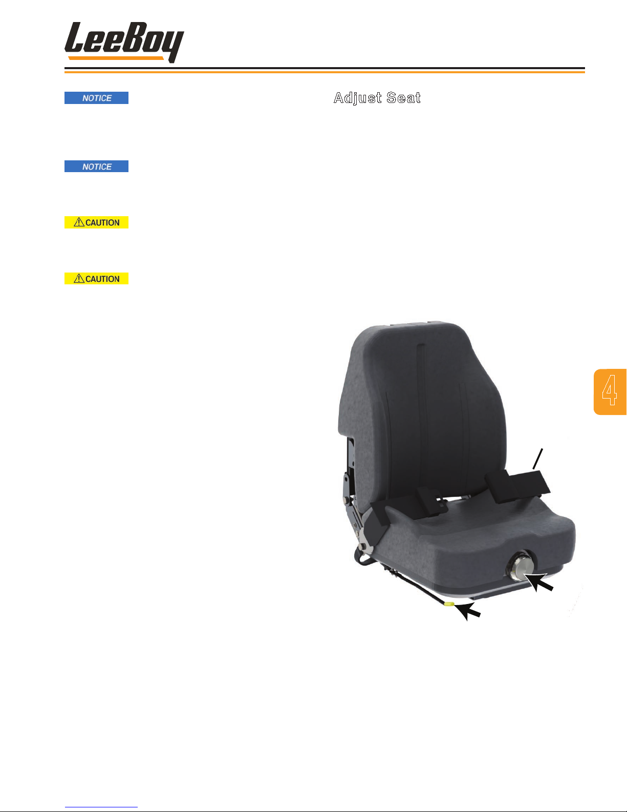
2
Operation
Before driving on public roads, check
state and local laws that may apply to industrial
self-propelled machines. Additional lights, mirrors,
slow-moving vehicle emblems, or reectors may be
required.
STAY SEATED while operating
the grader. For additional safety, the grader will
automatically return to neutral and stop if the
operator stands while moving in forward or reverse.
Drive the grader with care and at
speeds compatible with conditions. Use extra
caution when operating over rough ground, on
slopes, while turning and “ditching.”
Drive cautiously when entering or
leaving a road shoulder to prevent a possible rollover.
Keep in mind:
• Walk around the grader and visually inspect the
entire machine, ensuring the moldboard and any
other attachments are in an elevated position before
starting the engine. Perform an operational safety
check before operating the grader, ensuring all
equipment functions properly and all safety equipment
(i.e., re extinguisher) is present.
Adjust Seat
The operator seat suspension provides comfort by
absorbing some of the machine movements during
operation. It can also be adjusted for individual comfort.
(Figure 4-24)
Always make seat and seat belt adjustments BEFORE
driving the grader. The seat belt is designed for safe
operator retention if the machine is involved in an
accident or roller-over.
• Use the suspension adjustment knob to set the
suspension for operator weight. Rotate knob to
increase or decrease setting as shown on the knob
face.
• Use the Seat Position adjustment lever to move the
seat forward or backward. Pull up on the lever to
adjust and release to lock into place.
4
• Adjust the seat, steering console and mirrors
BEFORE driving the grader. Wear your seat belt!
• Stop at all railroad crossings and look both ways
before proceeding.
• Stop the grader before changing gears and before
changing directions while driving.
• Watch your speed. At higher speeds, inertia forces
tend to make the grader less stable. Use extra
caution at intersections.
• Keep both ends of the moldboard high and within
the width of the grader when travelling. Pay extra
attention to obstacles that can damage the blade, i.e.,
manholes, signs, and road debris, etc.
• Be aware of trafc behind you. Pull over to the side of
the road to allow vehicles to safely pass if needed.
• Ensure proper warning ags and/or devices are in
place to warn trafc of road construction, slow-moving
vehicle or other trafc alerts. If working at night,
ensure the work site is well-lit and well-marked.
• Caution should be taken to keep the blade away from
the tires in all driving and operational situations.
Seatbelt
1
Figure 4-24. Seat Adjustment
1 - Suspension Adjustment Knob
2 - Seat Position Adjustment Lever
• If using front or rear attachments, work in low gear and
reduce speed.
LeeBoy 685D Motor Grader 4-17
Page 68
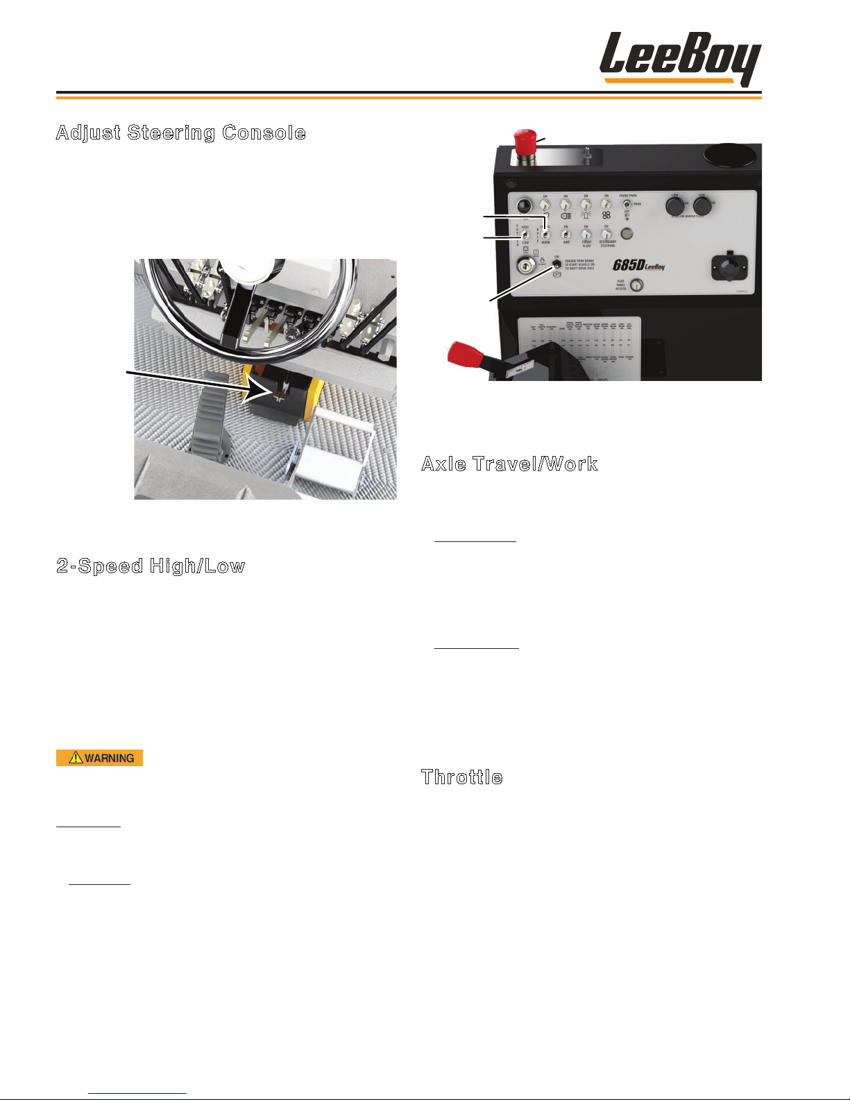
Operation
Adjust Steering Console
You can adjust the steering wheel console using the
console tilt lock toe pedal at the bottom of the steering
wheel column. (Figure 4-25) To adjust, simply depress
the toe pedal and push the steering console forward or
backward to a comfortable position, then release the tilt
lock pedal and it locks it into place.
Tilt Lock
Toe Pedal
Figure 4-25. Tilt Lock Toe Pedal
2-Speed High/Low
Grader speed is controlled by the 2-Speed High/Low
switch on the control panel to the right of the operator
seat. (Figure 4-26) This switch controls the rear axle
gearbox. Turn the switch down for Low gear. Always
use low gear while grading.
NOTE: You MUST STOP the machine on level
ground, place the FNR pedal in neutral and
engage the park brake to shift between high
and low gear.
E-Stop
Axle
Work/
Travel
2-Speed
High/
Low
Park Brake
Figure 4-26. 2-Speed, Axle Work/Travel,Park Brake
and E-Stop Controls
Axle Travel/Work
This switch controls the hydrostatic drive motor (Figure
4-26).
• Work Speed: Turn the switch DOWN for Work
speed. This maintains the hydrostatic drive motor
at a constant speed, but you can use the FNR pedal
to increase or decrease speed as needed. Use this
setting when grading for constant speed regardless
of load.
• Travel Speed: Turn the switch UP to select Travel
speed. This allows the grader to travel at a higher
speed when maximum torque is not needed, but
automatically slows when more torque is needed. Use
this setting when grading or traveling between job
sites.
ALWAYS move the FNR lever (or foot
pedal if equipped) SLOWLY after changing gears to
prevent lunging.
High Gear: Turn the switch UP for HIGH gear, used
when traveling to and from the work site. Maximum
speed in high gear is 20 mph (32 kph).
• Low Gear: Turn the switch DOWN for LOW gear.
The machine may reach up to 10 mph (16 kph),
depending upon speed in relation to torque condition.
NOTE: If equipped with the AWD option, it only
functions in Low gear.
Throttle
After selecting high or low gear, use the red-tipped
throttle lever beside the operator seat to increase or
decrease RPMs. (Figure 4-27)
A tachometer on the PV485 digital display controller
shows engine RPM speed. (Page 4-8)
• Pushing the throttle lever forward increases engine
speed.
• Pulling the throttle lever rearward decreases engine
speed.
LeeBoy 685D Motor Grader4-18
Page 69
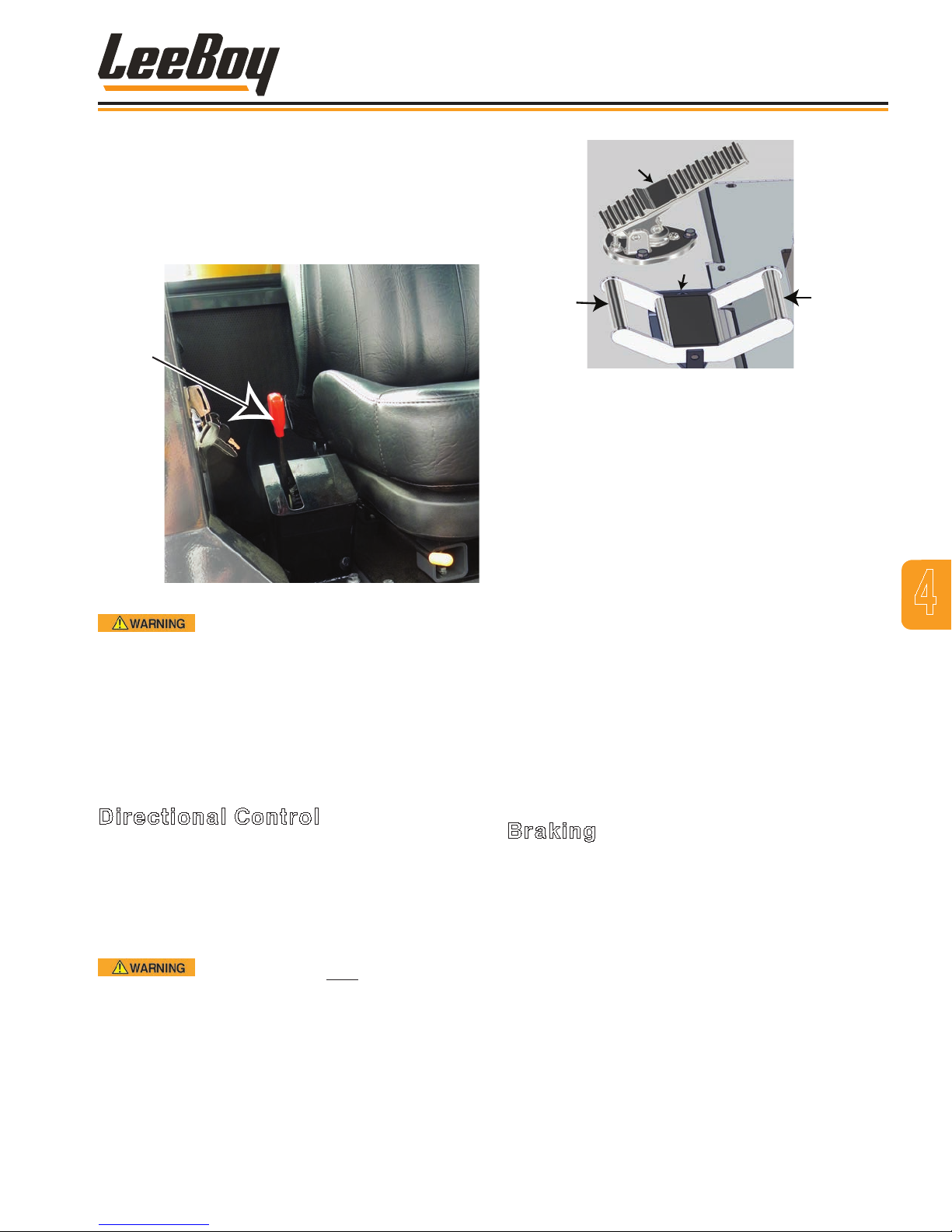
Operation
NOTE: Use slower ground speed when operating
with any attachment on the front or rear of
the grader.
After selecting high or low gear, use the red-tipped
throttle lever beside the operator seat to speed up and
slow down (increase or decrease RPMs). (Figure 4-27)
Throttle
Lever
Figure 4-27. Throttle Lever
Inexperienced grader operators
should always operate at slower speeds until gaining
the skills needed for faster operation. Extra care
must be taken by all operators in rough terrain,
bad weather and other hazardous situations to
prevent injury or even death. Before starting any
work, make sure you understand the machine, its
maneuverability, and its limitations.
Foot Brake
GENTLY
Press for
FNR
Reverse
Figure 4-28. FNR Pedal
To move the grader forward or in reverse:
1. Ensure the FNR pedal is in the neutral position, the
park brake is engaged, and follow the instructions
for Starting the Engine on Page 4-4.
2. Select High or Low gear.
NOTE: You MUST STOP the machine on level
ground and engage the park brake in
order to shift between High and Low speed
modes. (Figure 4-28)
3. Release the park brake by moving the switch
DOWN. (Figure 4-28)
• To drive forward, GENTLY push the front rail of
the FNR pedal forward with your foot.
• To drive in reverse, GENTLY push the back rail of
the FNR pedal backward with your foot.
• To stop, remove foot from pedal and allow it to
return to the center (neutral) position.
Press for
Forward
4
Directional Control
The 685D Motor Grader is equipped with a forward/
reverse variable-speed, hydrostatic transmission and
variable hydraulic motor that are controlled separately.
The FNR pedal controls the hydraulic ow and direction
of ow through the hydrostatic transmission. (Figure
4-28)
The FNR pedal is very sensitive.
Ensure nobody is near the grader before engaging
the FNR pedal and use only a little pressure on the
pedal when moving either direction to prevent the
grader from lunging.
LeeBoy 685D Motor Grader 4-19
Braking
Typically, operators use the FNR foot pedal for slowing
down by simply releasing it into neutral. This method is
recommended.
To quickly bring the grader to a complete stop, gently
step on the foot brake pedal. (Figure 4-28) Be sure
your seat belt is securely fastened as using the foot
brake will stop the grader very quickly and can abruptly
throw the operator in the direction of travel.
In an emergency, use the E-Stop (Emergency Stop)
button on top of the control panel. (Figure 4-26)
NOTE: If you use the E-Stop method, always check
brake function afterward as described
on Page 4-4. It is recommended that you
check brake function daily, but especially
important after E-Stop use.
Page 70
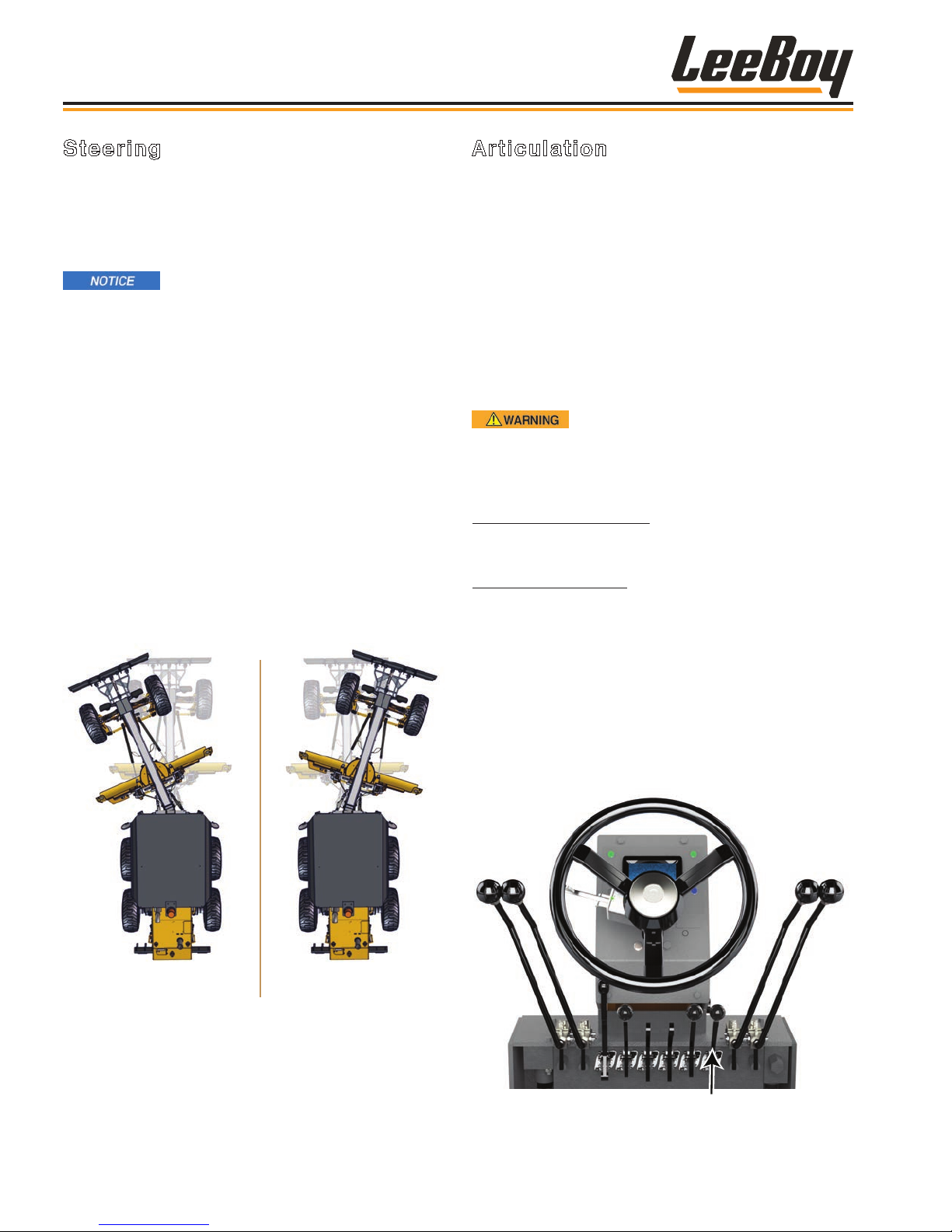
Operation
Steering
Steering a six-wheeled motor grader may seem a
little complex for inexperienced operators, but skilled
operators know the extra wheels can boost efciency
and productivity in all applications. An option for
secondary steering is also available.
Keep the tires properly inated to get
the best results. Over-inated tires result in less
traction between the tire and road surface. Airpressure differences in the rear tires can cause tire
slippage and grader bucking.
Operators steer the grader using a traditional steering
wheel. It is important to make slow turns to maintain
stability, especially for new operators. All operators
should become comfortable with driving and steering
the motor grader before operating at a work site.
The LeeBoy 685D Motor Grader has an articulated
frame, which means the front “boom” portion of the
machine can pivot left and right, adding exibility and
maneuverability for many applications. (Figure 4-29)
The front wheels can also be leaned in the direction of
the turn for more steering assistance in tight turns and
grading techniques. (Page 4-22)
Articulation
Articulating into turns gives the shortest turn radius
for close-quarter work, cul-de-sacs and corners.
Articulation also provides more control, maneuverability
and safety when operating in tight quarters, and
counters side draft when making a heavy cutting pass
or grading wet ditches. Experienced operators also use
articulation techniques to maintain a straight path when
working with a windrow or lessen the blade load without
using the circle.
The articulation angle can affect the stability of the
machine. Efcient and safe articulation requires skill and
experience to take advantage of its full capabilities.
Use articulation ONLY in WORK GEAR.
Articulation can adversely affect machine stability,
therefore, DO NOT articulate in Travel gear.
Other uses for articulation include:
Counteracting Side Loads: You can counteract side
draft when making a heavy cutting pass by articulating
the back frame toward the toe of the moldboard.
Reducing Blade Loads: Articulate the back frame
toward the heel of the moldboard to reduce blade loads
without “circling” the blade under the load or where
maximum circle torque has been reached. This reduces
the width of cut and the load.
Articulate
Left
Figure 4-29. Articulation
Use the articulate lever on the steering control column
to articulate left or right (Figure 4-30):
• To articulate to the left, push the articulate lever
forward.
• To articulate to the right, pull the articulate lever back.
Articulate
Right
Articulate Lever
Figure 4-30. Articulate Lever
LeeBoy 685D Motor Grader4-20
Page 71
Inexperienced operators should
pay particular attention and watch both ends of the
moldboard blade when articulating to ensure the
blade is far enough away to prevent slashing a tire.
For new operators, it’s a good idea to practice turning
around in both directions to get familiar with using
articulation:
1. ALWAYS raise the moldboard (and any other
attachments) before turning the grader around.
(See Pages 4-23 to 4-24)
Operation
2. Set the Work/Travel switch to Work mode.
3. With the grader moving forward, turn the steering
wheel into the direction of the turn (the example in
Figure 4-31 is shown turning left), then move the
articulate lever forward if turning left or move the
lever back if turning right.
Figure 4-31. Turning Around Using Articulation
4. Upon completing the turn, move the articulate lever
back to it’s neutral position as you straighten the
steering wheel.
Figure 4-32. Front Wheel Lean
Front Wheel Lean
The proper use of the front wheels is a great aid in
steering and grading. The front wheels can be leaned in
either direction to lean the weight of the grader toward
and balance the weight against the pulling forces
(inertia) caused by the angled moldboard. The leaning
wheels, combined with the angled blade, increase
the grader’s ability to excavate and move material in a
specic direction.
The top of the front wheels are normally leaned in the
direction the material comes off the angled moldboard
(heel) to counteract inertia exerted on the front end of
the moldboard (toe). Leaning the front wheels can also
be used in conjunction with articulation to achieve an
even tighter turning radius if needed. Front wheel lean
helps keep the front wheels from sliding off the desired
straight line, shortens turn radius, reduces front sliding
on slopes, and is especially helpful when cutting ditches.
Use the front wheel lean feature:
• To increase slope angle capability when cutting high
or ditch-back slopes. It allows keeping the front
wheels in a vertical position when working slopes or
ditches to enhance steering in this terrain.
4
LeeBoy 685D Motor Grader 4-21
• For cutting ditches, lean the wheels toward the top of
the ditch.
• For high bank-cutting operations, lean the top of the
wheels toward the bank to counteract inertia.
• For side slope work, use articulation and lean the front
wheels up the slope.
Page 72
Operation
Use the wheel lean lever on the steering control column
to lean the front wheels left or right (Figure 4-33):
• Push the lever forward to lean the wheels left.
• Pull the lever back to lean the wheels right.
Wheel Lean Lever
Figure 4-33. Front Wheel Lean Lever
MOTOR GRADER TERMS
To understand techniques and applications discussed
on the following pages, an understanding of grading
terms is essential:
Moldboard Blade: The moldboard blade is attached
the bottom of the moldboard. This is what makes
contact with the surface.
Moldboard Toe: This is the leading end of the
moldboard closest to the front wheels. (Figure 4-34)
Moldboard Heel: This is the trailing end of the
moldboard farthest from the front wheels.
Moldboard Angle: The angle of the moldboard as
measured from the moldboard toe to the center line of
the front frame.
Moldboard Pitch: Tilting the top of the moldboard
forward or backward from its vertical position is pitch.
Moldboard Side Shift: The moldboard can be shifted
outward up to three (3) feet right or left.
Turntable (Circle): This is the circular part of motor
grader located under the frame. The turntable (or circle)
rotates, which moves the moldboard blade left and right.
Windrow: This is the ridge of loose material, also known
as a berm, that pushes to the side while grading.
Angle
Crown: This is the process of building up the middle
part of a road bed so water will drain to the sides. This is
especially important for road maintenance projects.
Scarify: This term means loosening or ripping up
the grading surface. The 685D Motor Grader offers
scarier optional attachments that mount on the front or
rear of the grader.
Toe
Turntable
(Circle)
Heel
Figure 4-34. Moldboard Angle, Toe and Heel
LeeBoy 685D Motor Grader4-22
Page 73
Operation
Pitching the moldboard forward or backward changes
the depth of cut across the entire moldboard. (Figure
4-36) Most grading passes start with the top of the
moldboard tilted about two inches (5 cm) ahead of the
bottom. For better penetration, tilt the moldboard more
rearward.
Figure 4-35. Grading with the Moldboard
MOLDBOARD
Grading is most efcient when material is consistently
rolling across the moldboard blade toe to heel. This is
achieved by proper moldboard angle while grading. The
operation of the entire motor grader machine rotates
around the moldboard blade and its precise movement
from the turntable and frame to the hydraulic cylinders
and gears. Levers on the steering column control
moldboard movement.
DO NOT allow others near the grader
while working, especially near the moldboard area.
Serious injury or even death can occur if a bystander
is struck by a moving moldboard.
Moldboard angle is one of the most important elements
of grading since the angle is what allows material to roll
along the moldboard. Improper blade angle and pitch
will overwork the grader and burn more fuel. It can also
cause unnecessary wear on the machine, moldboard
and attachments.
NOTE: When the blade is angled straight across
(perpendicular to the direction of
movement, it is at 0 degrees.
• Most grader work is done at moldboard angles of
10 to 45 degrees.
Forward Pitch (Tilt)
Figure 4-36. Moldboard Pitch (Tilt)
• For normal cutting action, the moldboard blade is
used in the upright position only slightly tilted forward.
• Tilting the moldboard forward allows material to roll
for spreading or compacting. Use a forward pitch to
make light cuts, spread material, smoothing material
and typical road maintenance projects.
There are high levels of wear and tear
on the moldboard blade, therefore, inspect the blade
daily. Replace the blade if worn or damaged. (See
Section 5) For maximum cutting edge life in road
maintenance work, maintain consistent moldboard
pitch as frequent position changes can result in
accelerated blade edge wear.
Counteract the resulting side thrust
(inertia) from blade angle and pitch by leaning the
wheels toward the moldboard heel. You may also
need to articulate slightly toward the blade toe for
additional side thrust control.
Rearward Pitch (Tilt)
4
• Lower moldboard angles (10 - 30 degrees) are
normally used for light, free-owing material.
• Higher moldboard angles (30 - 50 degrees)
are required when processing wet and sticky
material, mixing large windrows, and ditching,
among others. The greater the moldboard angle,
the more material is carried across, allowing for
deeper cuts and heavier grading.
LeeBoy 685D Motor Grader 4-23
Page 74
Operation
2
1
NOTE: Continuing to push both moldboard lift
levers forward moves the moldboard into
“oat” detent, if equipped with this option.
3
4
5
5 - Moldboard Tilt Lever: Push this lever forward to tilt
the top of the moldboard blade forward. Pull the lever
back to tilt the top of the moldboard backward.
Floating means there is no down pressure
(except the weight of the blade). This is
useful for moving ne materials across the
surface, snow removal, and removing loose
material from a hard surface. Pull both
levers back to release the oat detent.
Figure 4-37. Moldboard Control Levers
1 - Moldboard Angle Lever: Push this lever forward to
rotate the moldboard blade to the right. Pull the lever
back to rotate the moldboard blade to the left. (Figure
4-37)
2 - Moldboard Slide Lever: The moldboard slide lever
enables the moldboard to shift outward (left or right)
as much as three feet (.9 m) to extend the moldboard
blade’s reach. Push this lever forward to shift the
moldboard to the right. Pull the lever back to shift the
moldboard to the left.
3 - Moldboard Lift Lever (Left): Push this lever forward
to lower the left side of the moldboard. Pull it back to
raise the left side of the moldboard.
4 - Moldboard Lift Lever (Right): Push this lever
forward to lower the right side of the moldboard. Pull it
back to raise the right side of the moldboard.
NOTE: Push both moldboard lift levers together to
lower the entire moldboard. Pulling both
moldboard lift levers back to raise the
entire moldboard.
Circle Turn Cushion Valve
The circle turn cushion valve is an optional valve built
into the steering and circle (turntable) turn circuits at the
factory. It protects both sides of the circuit from high
pressure spikes created by shock (extreme) loads. If
the moldboard strikes an immovable object, this valve
allows the circle (turntable) to turn, thus preventing
damage to the machine.
LeeBoy 685D Motor Grader4-24
Page 75
Operation
GRADER ATTACHMENTS
The LeeBoy 685D Motor Grader can be equipped with a
variety of optional attachments to extend its capabilities
for grading, plowing and scarifying. These rugged
attachments can be hydraulically raised and lowered.
Front attachments are designed for maximum
operator visibility, safety and efciency. A variety of
interchangeable attachments can be mounted on
the front nose of the grader. A rear scarier option is
mounted at the factory, and typically is not removed.
(See Page 4-27)
Both front and rear attachment
lift cylinders and joints must be lubricated with
multipurpose grease weekly. (See Page 5-7)
Mounting Front Attachments
Replacing optional attachments to the front nose of the
grader is not difcult, but care must be taken to prevent
injury or damage as the attachments are heavy. It is
recommended an assistant help when mounting or
exchanging grader attachments.
ALWAYS use a sling or secured lift
to raise high enough for installation or removal on
the nose plate. Place a block under the attachment,
ensuring the attachment cannot fall and possibly
cause serious injury or damage.
Use the following procedure to mount a front attachment
(reverse procedure to remove):
1. If replacing a front attachment, rst disconnect and
cap hydraulic hoses to prevent contamination from
entering the hydraulic system. (Figure 4-40)
2. Using a sling or lift, raise the attachment so that all
six holes on the attachment plate align with the six
holes on the grader nose plate.
3. Install bolts and washers. Torque to 260 ft lbs.
Figure 4-38. Front Blade Option
The front blade attachment is a dozer blade used for
moving material, backlling and general plowing or
grading. Some operators also use it for snow plowing.
NOTE: Be especially careful if using the front blade
for snow plowing. Objects can be hidden
under the snow, so be sure to wear your
seat belt and work in the direction of trafc
when possible. Snow also adversely affects
traction, so use tire chains or equip the
grader with snow tires.
There are two front-mounted scarier options available:
A standard scarier and blade-mounted, ip-down
scarier
See your authorized dealer to purchase optional front
attachments.
Bolts and
Washers
Lift
Nose
Plate
Cylinder
Figure 4-39. Mounting Front Attachment
4
LeeBoy 685D Motor Grader 4-25
Page 76
Operation
4. Uncap and connect the two hydraulic hoses as
shown in Figure 4-41.
• Connect hydraulic hose at top of the lift cylinder
to the right side of the grader nose.
• Connect hydraulic hose at bottom of the lift
cylinder to the left side of the grader nose.
Ensure the attachment is properly
secured before operating to prevent serious injury or
damage.
Hydraulic Hose
Connection
Figure 4-40. Connect Hydraulic Hoses
Front Blade Float
The front blade oat option allows the blade to follow
a varying surface using only the weight of the drawbar,
circle and moldboard. Blade oat prevents damage
to uneven surfaces but requires a hard surface such
as asphalt or frozen ground to prevent gouging the
surface. In areas with loose gravel on the road surface,
using blade oat may windrow the gravel onto the road
shoulder.
Turn the Front Float switch on the main control panel up
to the ON position to engage this feature. (Figure 4-42)
Operating Front Attachments
The front blade lever is used to raise and lower all front
attachments. This lever is located on the steering
control panel. (Figure 4-41)
• Pull lever rearward to raise the attachment.
• Push lever forward to lower the attachment.
Front
Float
Figure 4-42. Front Blade Float Switch
Front Attachments Lever
Figure 4-41. Front Attachments Control Lever
LeeBoy 685D Motor Grader4-26
Page 77
Operation
Scarifiers
Scariers strong enough to penetrate material too hard
for the moldboard blade to cut or spread are available
that can be mounted on the front or rear of the grader.
Scarier “teeth” shanks “rip” and loosen earth, gravel,
and similar surfaces. After “scarifying” compacted or
hard material, the operator can then use the moldboard
to grade and reshape the road surface.
The rear-mounted scarier option features nine large,
replaceable teeth. (Figure 4-43)
A front blade-mounted, ip-down scarier option offers
the convenience of using either component at the front
of the grader. (Figure 4-45) If the job needs scarifying
operations, mount the attachment with the scarier side
down. Or “ip” attachment the other direction and mount
on the nose plate to use the dozer blade.
Scarier
Dozer
Blade
Figure 4-45. Front Blade-Mounted, Flip-Down
Scarier Attachment
Keep these items in mind when using a scarier:
4
Figure 4-43. Using the Rear Scarier
The front scarier option also features nine replaceable
teeth mounted on a plow-shaped plate. (Figure 4-44)
Figure 4-44. Front Scarier Attachment
• Be sure to drive in a straight line when the scarier is
in the ground to avoid breaking the teeth.
• The proper way to reshape a dirt road with ruts
and potholes is to scarify its surface to the depth
of the depressions to break up all the compacted
surrounding surface.
• To control dust, especially on a dirt road, wet the
surface. This also helps supporting the binding of
ll material if the dirt road will be compacted after
grading.
• To scarify extremely hard or compacted material,
remove alternate scarier teeth. DO NOT remove
more than ve teeth as the force against the
remaining teeth could shear them off.
NEVER make sharp turns or articulate
with scarier teeth in the ground. DO NOT drag the
scarier teeth along hard surfaces such as pavement
or large rocks. Damage or bent/broken teeth can
occur.
Scarify down the slope for better
stability whenever possible. If scarifying or ripping
across a slope, keep the moldboard parallel with the
front axle, extended toward the downhill side, and
lowered close to the ground to provide protection
against rolling over.
LeeBoy 685D Motor Grader 4-27
Page 78
Operation
Operating a Scarifier
Use the following procedure for scarifying roads or
other areas using the optional rear scarier:
1. Raise the moldboard at least one foot (.304 m) off
the ground to allow unrestricted movement. Rotate
the moldboard so that it is perpendicular with the
frame and pitch the blade forward halfway.
2. Position the grader ahead of the working area and
ensure the front wheels are vertical.
3. Slowly move the grader forward.
If the rear wheels lose traction, raise
the scarier until the wheels regain traction.
4. At the starting point for the job and while still moving,
lower the scarier.
• If equipped with a rear scarier, use the rear
scarier lever shown in Figure 4-46.
Replacing Scarifier Teeth
The scarier tooth supports are adjustable and secured
with pin locks.
Always support the scarier and other
attachments using a block or sling before servicing.
1. Raise the scarier. Support the scarier on
blocks or use a sling for support.
2. Using a pry bar or lock pin tool, remove the shank
lock pin and tooth from the scarier frame. (Figure
4-47)
• If only removing tooth, be sure to store tooth
shank and locking pin together for later use.
Pin
Lock
(Pin
Lock)
Tooth
Shank
Rear Attachment Lever
Figure 4-46. Rear Attachment Control Lever
5. When nished with the rst pass, raise the scarier
by pulling rearward on the scarier lever.
6. If more passes are needed, repeat the procedure.
DO NOT remove more than ve teeth
as the force against the remaining teeth could shear
them off.
Figure 4-47. Scarier Shank Lock Pin and Tooth
3. Position new tooth shank into the desired slot on the
scarier frame.
4. Insert lock pin. It is recommended using a rubber
hammer if you wish to hammer the lock pin back into
place to prevent damage.
LeeBoy 685D Motor Grader4-28
Page 79
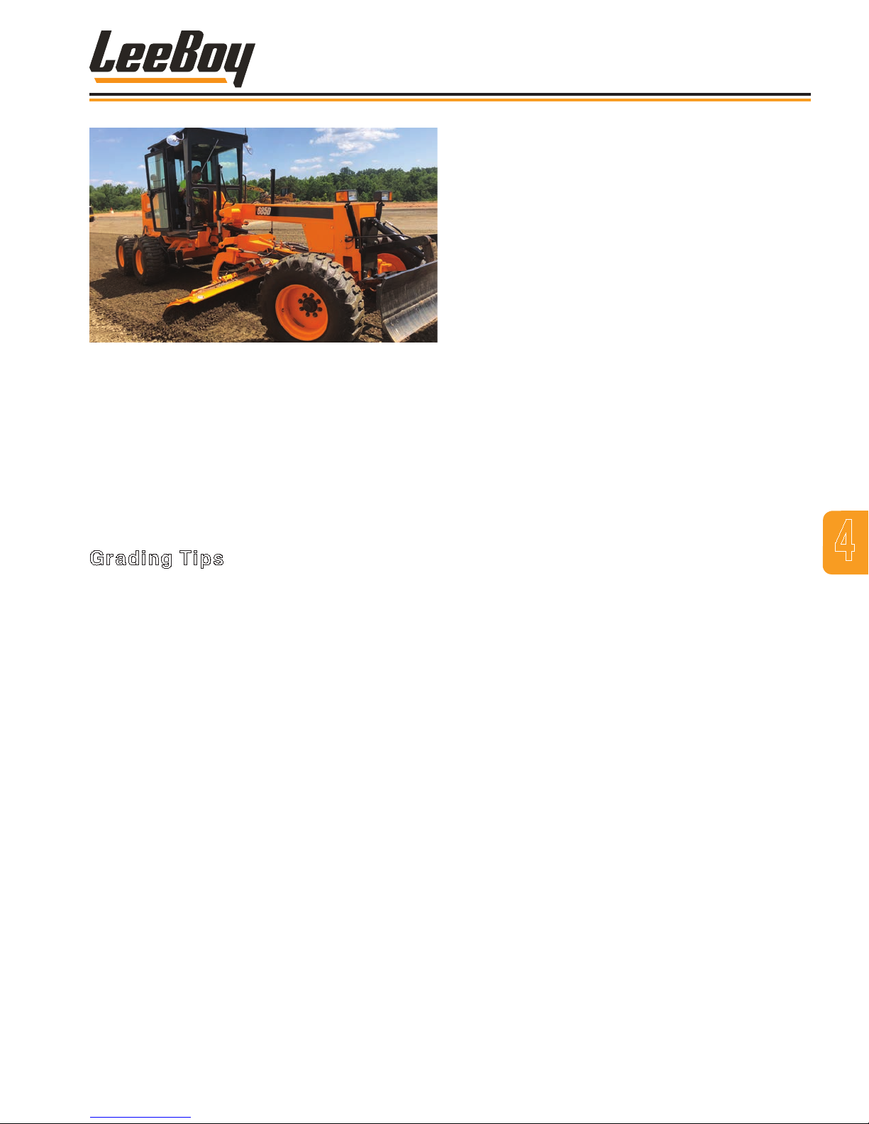
Figure 4-48. Operating the 685D Motor Grader
OPERATING TECHNIQUES
The information provided on the following pages are
basic grading techniques. Every road construction
project is different with a unique set of variables
operators must take into account, such as terrain and
weather conditions, that affect operation. Mastering
such versatile grading skills requires experience.
Grading Tips
The following are general tips for project success when
operating your motor grader:
• Keep your grader and its attachments in good
mechanical condition. Pay extra attention in checking
for wear on the moldboard blade edge often. If
the blade edge is worn or damaged, contact your
authorized dealer for replacement.
• Be very familiar with the controls, attachments and
component functions. Be especially familiar with
blade movement that are made possible by the
hydraulic controls for different tasks. Know the
settings needed, angle, height, and what you want the
blade to do before you lower it to the ground.
Operation
• Moldboard angles of 10 - 30 degrees can be used for
light, free-owing material. Higher angles of 30 - 50
degrees is required when processing wet or sticky
material, mixing large windrows, and ditch work.
• Remember that pitching, or tilting the top of the
moldboard tip forward or backward, changes the
depth of the cut across the entire moldboard.
• If material starts to ow around the leading end of the
moldboard or the rolling action stops, increase the
blade angle.
• Apply only enough downward pressure with the
moldboard to accomplish the task. Excessive
pressure, especially on hard, dry surfaces, causes
rapid cutting edge wear, requires more horsepower
and fuel, and reduces productivity.
• Choosing the right speed for a task is just as important
as the moldboard angle. Drive slowly for delicate
work, but faster if removing rocks from a road surface.
• Avoid moving material more often than needed.
• Trimming is much easier with good compaction.
• If dressing a road, the surface should be moist
whether from rain or hosed from a water truck. Ensure
there is good drainage by grading with appropriate
crown.
• Articulating the rear frame toward the toe of the
moldboard by 2 - 5 degrees helps reduce the
machine’s tendency to bounce. This is extremely
effective when cutting “washboards.”
• Wheel leans can help an operator make steering
adjustments without taking hands off the controls.
Wheel lean is also useful for moving heavy windrows.
• Graders remove snow the same as snow plows. Be
sure to raise the moldboard 1/2 to 1 inch (1.3 - 2.5 cm)
if removing snow from uneven pavement or other
surfaces to prevent damage to the blade.
4
• Every job requires a specic blade setting with the
right speed for optimum production. Be familiar with
the moldboard blade movements. Know what you
want to do before lowering the moldboard.
LeeBoy 685D Motor Grader 4-29
Page 80
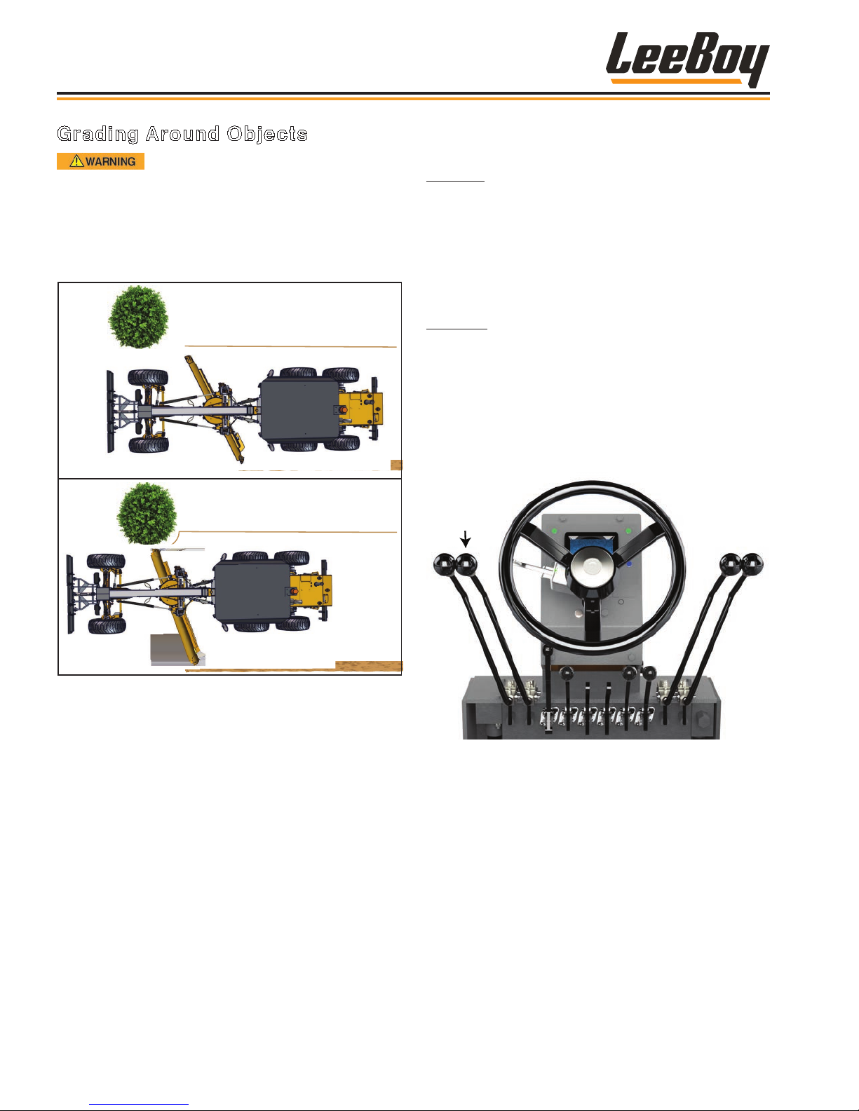
Operation
Grading Around Objects
Avoid hazards and obstructions
such as overhangs, ledges, slide areas, electrical
lines, underground cable, water main and gas lines,
etc., that can result in serious injury or even death.
ALWAYS request assistance from the appropriate
authorities if operating close to electrical or gas
lines, water main and any underground cables.
Method 1: Slowly drive around.
Method 2: Use moldboard slide.
There are two basic methods for grading around objects
(Figure 4-49):
Method 1:
1. Reduce speed before approaching object.
2. Slowly maneuver the grader around the object,
driving as close as possible (depending upon
skill level) to reduce the amount of hand shoveling
needed.
Method 2:
1. Reduce speed before approaching object.
2. Use the moldboard slide shift lever to shift the
moldboard in the opposite direction of the object.
(Figure 4-50)
• Pull lever to slide the moldboard left.
• Push lever to slide the moldboard right.
Moldboard
Slide Lever
Figure 4-49. Grading Around Objects
Figure 4-50. Moldboard Slide Lever
3. Slowly follow the shape of the object, sliding the
moldboard more if needed.
4. Slide the moldboard back to its original position
after passing the object.
LeeBoy 685D Motor Grader4-30
Page 81
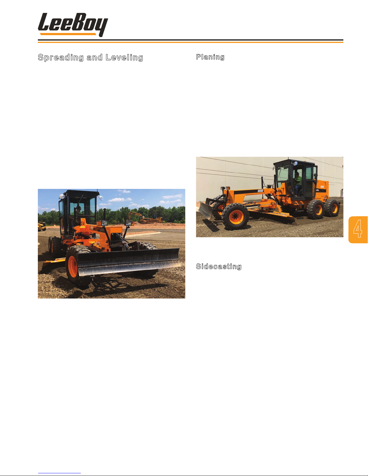
Operation
Spreading and Leveling
The 685D Motor Grader can also be used for spreading,
leveling, planing and side casting material. Graders
have less power and traction than dozers, but can move
the loads faster. The moldboard blade is lower and
more concave, which gives the grader increased rolling
action of the load so more material is pushed without
spilling over the top.
NOTE: Do not pile windrows in front of the rear
wheels because it will adversely affect
traction and grader control.
• If there is space to work around the sides of the
windrows, extend the blade well to the side and
reduce the windrow using a series of side cuts.
• Leveling large windrows may require two or more side
cuts.
Planing
Set the blade at an angle to “plane off” irregular surfaces
and use that material to ll hollows:
1. Cut enough material to keep some in front of the
blade, moving the loosened material forward to
distribute it evenly.
2. On the next pass, pick up the windrow left from the
trailing edge of the blade.
3. On the nal pass, make a lighter cut and lift the
trailing edge of the blade enough to allow surplus
material to under rather than around the end to
avoid leaving a ridge.
Figure 4-51. Leveling a Windrow
• You can also use articulation and lean the wheels
slightly to move and spread large windrows:
• Angle the moldboard blade toward the windrow,
tilting it forward slightly. Be sure the moldboard is
positioned high enough above the surface to obtain
the desired depth.
• Lean the front wheels slightly in the opposite direction
to overcome side thrust.
4
Figure 4-52. Planing
Sidecasting
The side casting technique is often used for lling
ditches, shaping and road maintenance.
• To shape and maintain most roads, the moldboard
blade should be at an angle of 25 - 30 degrees.
• Decrease the angle for spreading windrows.
• Increase the angle for hard cuts and ditching.
1. Angle the moldboard blade so the load being
pushed at the toe rolls off the heel. This rolling
action assists side movement.
2. Move forward, side casting the material into the
ditch.
3. Make the passes necessary to compact the ll.
LeeBoy 685D Motor Grader 4-31
Page 82
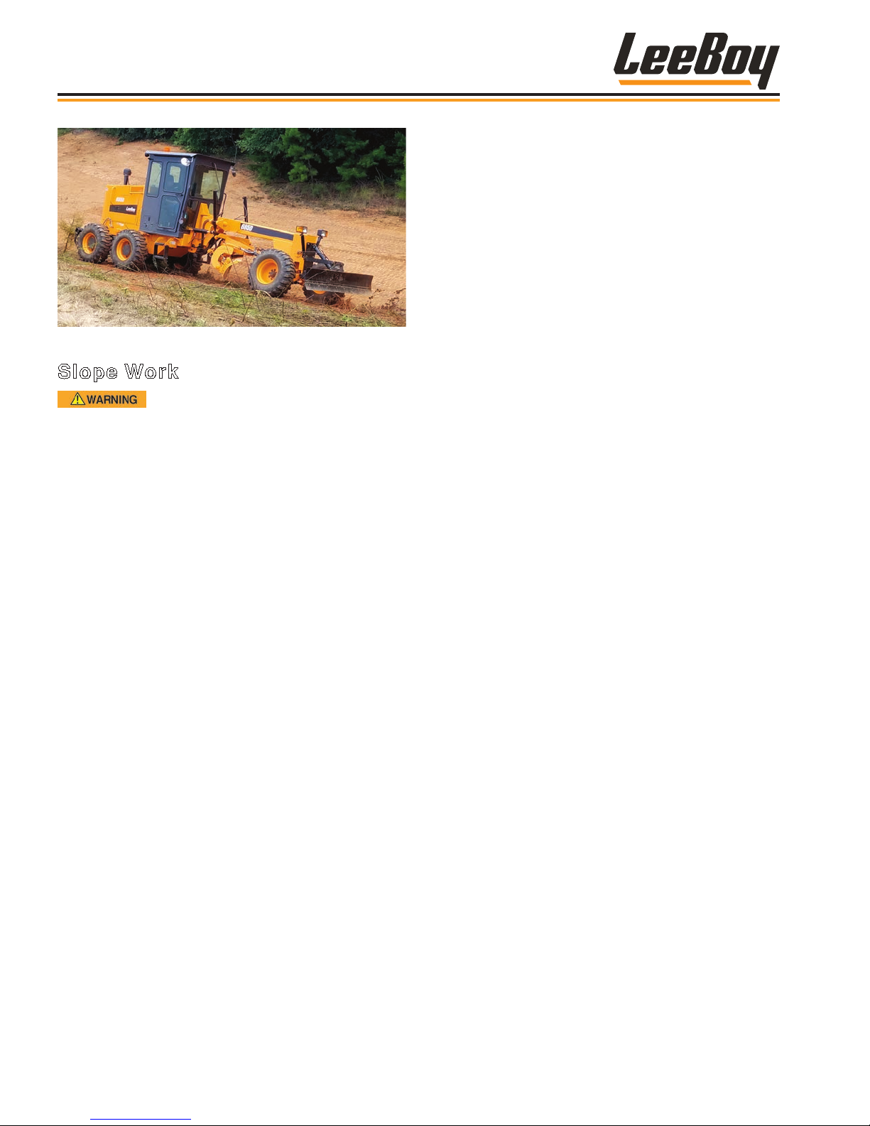
Operation
Figure 4-53. Slope Work
Slope Work
Use extreme caution and drive slowly
while working on slopes. While unlikely, the grader
can roll over and result in serious injury or even
death.
Operating the grader on slopes can be dangerous,
especially for inexperienced operators. Maneuvering
on or along steep slopes requires excellent operator
skills and experience.
The slope perpendicular to the machine’s direction of
travel is commonly known as “side sloping.” Typically
steep slopes require articulation to navigate, but ONLY
experienced operators familiar with the machine
should perform this type of work.
The slope parallel to the machine’s direction of travel
that affects the grader’s ability to travel up or down
terrain is known as gradeability. This is established
by the grader’s ability to stop without skidding the tire
while moving downhill. The grader can climb steeper
slopes than it can safely descend. If working on hills and
slopes, it is important to consider the following points:
• New lls may give way with the grader’s weight while
rocky surfaces can cause side slipping.
• Position the moldboard toe outside and behind the
uphill wheel so the moldboard heel deposits material
outside the downhill tandem wheels.
• Excessive loads or side draft can also cause wheel
slippage as the downhill tires “dig in” and increase the
angle of the grader.
• Articulation and wheel lean angles also affect the
stability of the grader. Only experienced operators
should articulate when working on slopes.
• Lean the front wheel vertically and position the uphill
front wheel on the edge of the windrow created from
previous pass to provide extra stability and create an
even grade.
If possible, make a rst pass from above the slope to
establish the moldboard blade angle you will need.
Experienced grader operators can also use articulation
for added reach, ensuring the tandem wheels (rear) are
on a level surface.
1. Angle the toe of the moldboard outside and behind
the uphill wheel, with the moldboard heel downhill
outside the tandem wheels.
2. Tilt the moldboard forward slightly and make the rst
pass.
3. On the second pass, lean the front wheels toward
slope and slightly articulate rear wheels down slope
to increase machine stability.
4. Make as many passes as needed for the desired
result, then clean with the moldboard less angled
but tilted more forward away to clean any windrow
away from the bottom of the slope.
• NEVER climb a slope steeper than you can safely
descend.
• At higher speeds, inertia forces make the grader less
stable. If you must work on a slope, work SLOWLY.
• Attachments can cause the grader to balance
differently. Ample allowance for the moldboard
and any other attachments should be made where
the terrain or surface is uneven to avoid damage to
attachments or injury from an unbalanced machine.
The position of the moldboard can affect the stability
of the grader considerably.
LeeBoy 685D Motor Grader4-32
Page 83
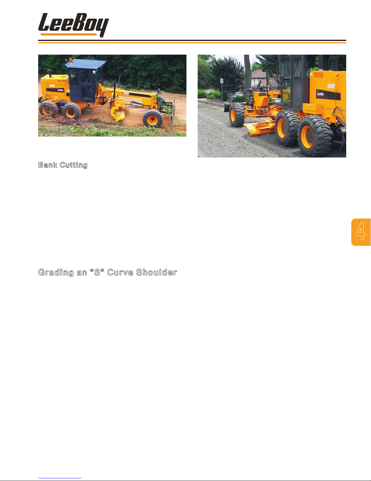
Figure 4-54. Bank Cutting
Operation
Bank Cutting
1. Make a rst pass at base of bank to level and
smooth a platform for the machine.
2. Tilt the moldboard slightly forward and sharply
angle the moldboard so the heel is in the opposite
direction of the bank you’re cutting. (You can
articulate slightly if more reach is needed.)
3. After making the bank cut, make a second pass with
the moldboard less angled but tilted more forward
to clean any loose material from the bottom of the
bank.
Grading an “S” Curve Shoulder
1. Slowly approach the rst curve.
2. Lean the front wheels slightly toward the opposite
direction of the curve to counteract side thrust.
• Push the lever forward to lean the wheels left.
• Pull the lever back to lean the wheels right.
3. Position the toe of the moldboard behind and
outside the front wheel closest to the edge of the
shoulder (in the opposite direction of the wheel
lean).
4. As you straighten the grader when nishing the
curve, return wheels to their normal position.
5. Slowly approach the second curve and repeat
Steps 2 - 4.
NOTE: If a windrow has been created while grading,
make a “clean-up” pass and reshape the
shoulder if necessary.
Figure 4-55. Road Maintenance
ROAD MAINTENANCE
Much of a grader’s road maintenance work involves
smoothing, shaping the travel surface and providing
drainage to prevent road deterioration.
Begin road maintenance work by tipping the top of
the moldboard approximately two inches ahead of the
cutting edge, then adjust to the material conditions.
Maintaining the material rolling action across the
moldboard blade reduces the horsepower required and
provides maximum productivity.
• The most important factor in road maintenance
grading is providing and maintaining a good drainage
system. Drainage of water from the road surface to a
ditch, even a minimal ditch, helps maintain good road
conditions longer.
• Remember that tipping the moldboard forwards or
backwards changes the depth of cut across the entire
moldboard. The best time to reshape earth and gravel
roads is after it’s rained. Dry roads should be sprayed
with water before grading for easy compaction and to
minimize dust while working.
• Articulating the rear frame toward the tow of the
moldboard 2 - 5 degrees helps reduce the motor
grader’s tendency to bounce.
• Keep the turntable circle clean. Material buildup may
increase wear and prevent smooth material rolling
action, reducing productivity.
4
LeeBoy 685D Motor Grader 4-33
Page 84
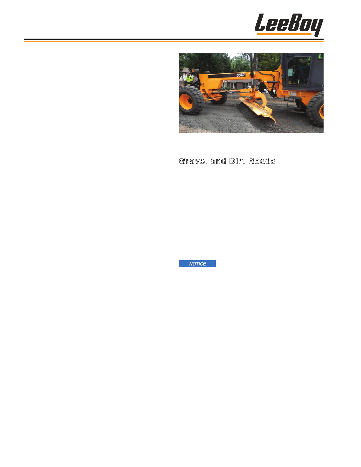
Operation
• For the widest possible pass on the travel surface,
keep the moldboard angle as square to the frame
as possible. If material starts to ow around the
moldboard toe or the rolling action stops, increase the
blade angle.
• The moldboard blade’s tip angle should be position
with the cutting edge at 90 degrees to the road
surface so the downward pressure places less stress
on the cutting edge and retaining bolts. To cut hard
material or for nishing work, tilt the moldboard further
forward.
• Keep your travel speed between 3 - 5 mph (4.8 - 8
kph) for maximum productivity with less machine
bounce. At higher speeds, the grader can “lope” or
bounce, causing ridges and depressions. Moisture,
material quality and road grade stability vary, so
operating speed must be slow enough to ensure the
grader remains stable.
• Grader efciency is directly proportional to the
number of passes made. Operator skill and project
good planning are most important for eliminating
unnecessary passes that increase time and cost of
the job.
• Before performing any road maintenance project, a
formal project plan or specications to control the
work is an important factor in road improvement. Be
sure to check with local and state departments of
transportation about roadway construction standards
and requirements before beginning the project. You
may also need to contact utility companies to verify
location of any utilities within the construction area
and arrange for temporary location if needed.
• Tree stumps, large rocks and other obstructions need
to be cleared and removed before grading. Tree
branches extending over the roadbed may also need
to be trimmed for adequate grader clearance.
• On straight sections, steer the grader as straight as
possible to maintain a straight shoulder and uniform
crown on the road.
Figure 4-56. Grading a Dirt or Gravel Road
Gravel and Dirt Roads
Level and maintain the gravel or dirt surface by working
the material across the road (or runway) from one side
to the other. The surface is easier to work with if it’s
damp. If grading a dry surface, work material from the
edges and shoulders toward the center to maintain a
satisfactory result.
Good gravel road maintenance depends upon proper
use of the grader and quality gravel that is the right
size correctly distributed onto the road surface. It is
important to properly shape the road surface before
spreading gravel to achieve quality results. The gravel
should also be damp.
Trafc, wind and grading can kick up
dust and cause loss of any binder material present,
so be cautious when disturbing dry road surfaces.
It is recommended that road maintenance grading
projects be done just after it rains, or use a water
truck to dampen the surface before grading. A damp
surface results in a better, smoother nish.
1. Start at the edge of the road shoulder and cut the
material into a windrow, depositing it toward the
center of the road (outside the tandem wheels).
2. Angle the moldboard 30 - 50 degrees and pitch
halfway back to cut. This removes ridges and
potholes.
NOTE: Scarify the surface rst on dirt roads with
deep ruts or extremely rough surfaces.
3. Lower moldboard until the toe and heel slightly
touch the ground, just enough to penetrate the
surface.
LeeBoy 685D Motor Grader4-34
Page 85
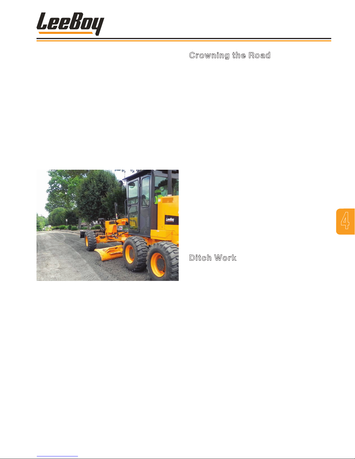
Operation
4. Lean the front wheels toward the moldboard heel as
you work toward the center of the road, maintaining
a straight course.
• You may need to adjust the moldboard slightly to
carry the material the length of the project.
• Pitch the moldboard forward and use very little
down pressure to feather the material at the end of
the pass.
5. Make as many passes as needed, continuing to
push the material toward the road center.
6. Repeat Steps 1 - 5 on the other side of the road.
7. Finish the road crown using the procedure
described in the next section.
Crowning the Road
Crowning a road is simply constructing the surface so
the center of the road is higher than the road edge to
allow water to drain. If the crown is not built properly,
water will be trapped and break up the road crust,
producing potholes and ruts. If also constructing
ditches, complete the ditch work rst, grading the
excess material to the center of the road, creating a
windrow.
• For good drainage, a road should have a crown of
1/3 inch (8.4 mm) to 1 /2 inch (12.7 mm) per foot (305
mm) as measured from the center of the road to the
outside edge where the road meets the shoulder.
To establish the road crown in the center and smooth
any ridges left:
1. Position the moldboard parallel to the front axle.
2. Raise the moldboard heel and tilt the moldboard
forward between 60 - 75 degrees.
3. Drive the grader straight down the center of the
windrow, keeping the moldboard high enough to
feather the material on both sides of the grader.
You can increase speed as this throws loose
material from the blade, feathers the material, and
blends the top.
4
Figure 4-57. Crowning
Ditch Work
Ditch work is typically done on the right side of the
grader. Cutting a ditch is called “Vee Ditching.”
Remember the following guidelines for ditch
construction:
• Make each ditch cut as deep as possible (without
stalling or losing control of the grader).
• Start with the blade positioned so the moldboard toe
is in line with the center of the lead wheel. Bring each
successive cut in from the edge of the bank slope so
the toe is in line with the ditch bottom on the nal cut.
• Ensure the moldboard is high enough off the surface
to allow unrestricted movement.
• Side shift the blade if needed to extend the moldboard
edge to the outside edge of the front wheel.
LeeBoy 685D Motor Grader 4-35
Page 86

Operation
1. Begin a ditch by establishing a marking cut.
• Pitch the moldboard forward halfway until top
of the moldboard is in line with the center of
the front tire, raising the heel just ahead of rear
wheels (so dirt spills between the rear tires).
• Rotate the moldboard so the toe is just behind
the outside edge of the right front wheel (about a
45-degree angle).
• Lean wheels toward the discharge end (heel) of
the moldboard.
• Make the rst cut light to establish the line of the
ditch.
2. Move the grader forward. As the front wheel
passes over the starting point of the ditch, lower
the moldboard toe, applying enough pressure to
penetrate the grounds surface 3-4 inches (7.6 - 10
cm).
3. On the second pass, position the wheels in the
ditch made by the rst pass to compensate for side
thrust and make a deeper cut. You can increase
speed on the second pass and apply as much down
pressure on the moldboard toe as the grader can
handle.
4. Continue along the ditch line until reaching the
nishing point.
NOTE: When making ditch cuts, windrows form
between the heel of the blade and the rear
wheel. Move or level these windrows when
either the ditch is at the planned depth or
the windrow becomes higher than the road
clearance of the grader. You can use this
material for the road shoulder.
6. Establish the road shoulder by sliding the
moldboard blade farther out, rotated to a 90-degree
angle (perpendicular with the frame), and tilted
slightly forward. Apply only enough downward
pressure to clean-up the ditch and skim the material
smoothly across the road shoulder.
Cul-De-Sacs
Articulating the grader helps when grading cul-desacs. Articulate the rear frame away from the curb (or
cul-de-sac radius), being careful not to articulate too
fast, and lean the wheels to keep the moldboard toe
position to the curb (or cul-de-sac radius). Remember
the center line crown extends all the way to the center
of the cul-de-sac, so do not straddle the crown or grade
perpendicular to the cul-de-sac entrance.
1. Angle the moldboard about 30 degrees and tilt
forward 5 - 10 degrees, keeping the toe toward
the outside cul-de-sac radius. Start grading at the
perimeter of the cul-de-sac in a circular pattern,
working material toward the center as you go.
2. To begin nishing the cul-de-sac, drive grader in the
opposite direction at the outside edge, forming a
windrow toward the center.
3. Tilt moldboard forward slightly and move windrows
toward the center of the cul-de-sac, checking the
slope as you grade.
4. When you have nished pushing all the excess
material to the center, straighten the moldboard
(parallel to the front axle) and push the excess
material out of the cul-de-sac entrance.
5. As dirt builds up between rear tires, make a cleanup pass, pushing material toward the road edge:
• Side-shift the moldboard blade toward the ditch
with front wheels positioned outside the windrow.
• Angle the moldboard heel between rear wheels
and pitch the moldboard blade slightly forward.
Be sure the moldboard toe is well beyond the
windrow to minimize spillage back into the ditch.
• Articulate the grader slightly to deposition
windrow between the rear tires if needed.
• Feather the material by raising and tilting the
moldboard blade slightly forward until all the
material passes under it.
LeeBoy 685D Motor Grader4-36
Page 87
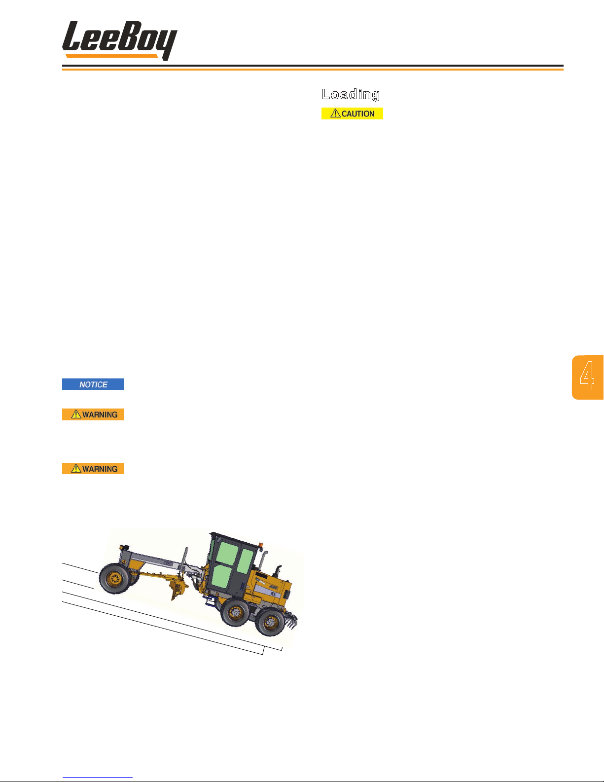
Operation
TRANSPORT
LeeBoy recommends transporting the grader on a at-
bed trailer rather than towing.
Remember the following guidelines:
• Ensure the ramp, trailer and transport vehicle are
strong enough to safely handle the size and weight of
this large industrial machine.
• Raise the moldboard and any other attachments to
the highest position. Pay close attention to clearance
when entering the ramp.
• NEVER load the grader onto a transport trailer without
assistance from another person serving as a ground
guide.
• Park the trailer in a clear, level area when loading or
unloading the machine.
• Keep the loading area clear. Work slowly and
carefully to avoid accidents.
• DO NOT place tie-down chains or cables over or
against hydraulic hoses, cylinders or valves, etc., to
prevent machine damage.
Check local and state regulations for
height restrictions on the transit route.
Ensure the transport route is free of
low bridges and other obstacles that can damage
the machine and/or cause a trafc accident that can
result in serious injury or even death.
Use extra caution steering when
loading and unloading the grader as slight steering
changes on ramps and trailers can cause the
machine to fall off. Serious injury or even death can
occur.
Loading
To prevent damage to the machine
undercarriage, frame and components, reduce
speed before wheels come into contact with loading
ramps or any abrupt change in the surface. The drive
system or other components can be damaged by
excessive shock.
1. Center grader with the ramp.
2. BEFORE moving onto the ramp:
• Ensure the hauling vehicle has its park brake
engaged.
• Ensure the moldboard and any attachments are
raised. The moldboard should be perpendicular
for added balance when moving up the ramp.
• Use only WORK gear.
3. SLOWLY drive the grader straight forward up the
ramp to position machine in the center of trailer.
The grader should centered between the left and
right side of the trailer.
4. Engage park brake and set engine speed to IDLE.
5. Angle the moldboard so it is inside the width of the
trailer. Lower the moldboard and any attachments
(without applying down-pressure) once the grader
is situated. Block the moldboard and all wheels.
6. Turn off the engine. Relieve residual hydraulic
pressure by operating all the console control levers
after turning off the engine.
7. Secure machine to the transport trailer using the
tie-down procedure that follows.
8. Ensure cab doors and all engine access panels are
closed and secured.
4
Figure 4-58. Correct Loading and Unloading
Position
LeeBoy 685D Motor Grader 4-37
9. Cover the exhaust with heavy-gauge plastic to
prevent turbo damage. Don’t forget to remove
before starting the engine!
Page 88
Operation
Unloading
1. Remove tie-down equipment.
2. Start the engine and allow machine to warm a few
minutes to ensure the hydraulic pump is providing
sufcient ow to operate all functions properly.
3. BEFORE backing machine down ramp:
• Ensure the moldboard and any attachments are
raised and secured to the machine frame.
• Use only WORK gear.
• Ensure the hauling vehicle has its park brake
engaged.
4. SLOWLY move machine down the ramp.
Tie-Down Procedure
1. Position grader in center of the trailer.
2. Place chocks at wheels to prevent machine
movement while securing and during transport.
3. Attach chains to the front and the rear D-ring tiedowns. (Figure 4-59). The front D-ring is located
under the frame. The rear D-rings are located on
each side of the frame behind the rear tandem tires.
4. Ensure that all chains are tightly secured before
transporting the grader.
TOWING
LeeBoy strongly recommends transporting the grader
on a truck trailer, but if you must tow the machine for a
short distance, use a tow hitch. A professional towing
service is recommended.
Improper towing methods can result in
severe personal injury or even death.
Stay clear of tow chains or cable,
especially when tension is applied. A broken cable
or chain can cause severe injury or even death. DO
NOT allow bystanders near the tow truck and grader
at any time. DO NOT allow the tow chain or bar to
contact any grader components.
Some state and local laws prohibit or
limit the use of tow chains on highways. Check state
and local regulations before towing with chains.
If the grader must be towed, remember the following
guidelines:
• DO NOT tow the grader a long distance. Transport it.
• Operator must be in the operator’s seat to control
steering and braking when towing the grader.
• NEVER tow the grader more than 5 mph (8 km/h).
• Ensure the tow truck has sufcient braking capacity to
stop the grader while being towed.
• Ensure the towline or tow bar is in good condition and
strong enough to tow the grader.
D-Ring
Figure 4-59. Tie-Down Locations
D-
Ring
• Sudden cab movement can cause the towline or tow
bar to break. When turning, keep the towing angle
and speed to a minimum. Proceed gradually and
smoothly, avoiding any sudden turns, braking or jerky
steering movements.
To tow the grader:
1. Block the wheels to prevent machine for moving
while preparing to tow the grader.
2. Ensure the FNR lever (or pedal) is in the NEUTRAL
position and the park brake is engaged.
3. Disconnect, plug and tag the hydraulic hoses on
the rear axle, being very careful to prevent any
contamination when plugging the hydraulic hose
ttings.
4. Use a small screwdriver or small pry bar to pull out
the shifting rod as far as it will go, then push it back
until you nd neutral. (Figure 4-60)
LeeBoy 685D Motor Grader4-38
Page 89
OPTIONS
Shifting
Cab Option
Operation
Rod
Figure 4-60. Shifting Rod
5. Locate both brake release screws on bottom of the
rear axle. (Figure 4-61)
Release Screw
The 685D Motor Grader offers the option of building
the machine with a comfort cab in lieu of the standard
canopy. (Figure 4-62)
Additional options for the cab include:
• Rear windshield wiper and washer.
• Air conditioning and heat with defroster.
• AM/FM radio.
4
Figure 4-61. Brake Release Screw
6. Using a caliper, measure the exact extension of the
screw and record measurement. Turn the screw
clockwise as far as it will go to release the brakes
for towing.
7. Repeat on the other side.
8. Raise and secure the moldboard and any other
attachments before towing. Use chains or cables
that are in good condition to secure attachments.
9. Fasten chain (or tow bar) to the front D-Ring.
10. Mark the center of the towline or tow bar with an
orange ag and attach a “Slow-Moving Vehicle” sign
onto the rear of the grader.
11. Remove wheel blocks and activate all warning lights
to alert trafc.
12. After towing the grader, readjust the brake release
screw according to the recorded measurement.
LeeBoy 685D Motor Grader 4-39
Figure 4-62. Cab Option
Page 90
Float
Operation
Sliding Moldboard
The 685D Motor Grader is equipped with an 11-foot
(3.35 m) sliding moldboard. A 12-foot (3.65 m) sliding
moldboard option is also available for even more reach.
See your LeeBoy dealer for installation.
Circle Side Shift
The circle side shift option allows the circle (or
turntable) and moldboard to reach far beyond the
wheels on either side. In its extreme position, it allows
the grader to position the moldboard blade in the bottom
of a highway ditch while traveling on secure footing on
the highway surface. For slope trimming, the moldboard
can swing out to either side and position at any angle
from horizontal to vertical.
Secondary Steering
The secondary steering option serves as a temporary
emergency steering back-up in the event of engine
failure or loss of hydraulic pressure. The secondary
steering system has a separate electrically-driven pump
that delivers hydraulic uid to the steering motor in the
event primary steering fails due to loss of hydraulic
pressure. This is an emergency feature that allows the
ability to steer the grader off the road, but is not intended
for traveling any distance as it will overheat quickly.
• To activate, turn the secondary steering switch on the
control panel up to the ON position. (Figure 4-64)
• Turn the switch down to disengage secondary
steering.
Secondary
Circle Side
Shift Lever
Figure 4-63. Circle Side Shift Lever
The circle side shift lever is located on the steering
control panel. (Figure 4-63)
• Pull lever rearward to shift the circle (and moldboard)
left.
• Push lever forward to shift the circle (and moldboard)
right.
Steering
AWD
Front
Figure 4-64. AWD, Secondary Steering and Front
Blade Float Switches
LeeBoy 685D Motor Grader4-40
Page 91
Operation
All-Wheel Drive (AWD)
The AWD option provides additional traction in all
weather conditions. The tires maintain a better grip
during rain or snow, in mud, and on gravel. AWD
provides better torque power for grading, pulling or lowspeed climbing and is especially useful when operating
on loose, low-traction surfaces.
DO NOT modify or alter any switch or
other component in the AWD system. Modications
can cause premature engagement or prevent
disengagement of the system, which could cause
injury and/or property damage.
NOTE: The Axle Work/Travel switch must be in the
Work position for AWD to function. AWD will
not function in the Travel mode.
To activate AWD:
1. Set the Axle Work/Travel switch to Work mode.
2. Turn the AWD switch to the ON position. (Figure
4-64)
3. Turn the AWD switch down (OFF) to disengage
AWD.
Cold Weather Engine Package
Reverse Camera System
A reverse camera system is also an available option.
(Figure 4-66) This additional safety feature assists
operators when moving in reverse by using the rear
camera to see directly behind the machine when moving
in reverse.
4
Figure 4-66. Back-Up Camera
The Cold Weather Engine package provides the ability
to keep the coolant system warm when the grader is not
in use for easier engine start-up during cold weather.
Simply plug the connector into the engine as shown in
Figure 4-65, then plug the other end into a standard
electrical outlet (110-volt). Be sure to remove the cord
and keep it in a safe place when not in use.
To Outlet
Connector
Figure 4-65. Cold Weather Engine Plug-In Location
LeeBoy 685D Motor Grader 4-41
Page 92

Operation
NOTES
LeeBoy 685D Motor Grader4-42
Page 93

Section 5
MAINTENANCE
Maintenance . . . . . . . . . . . . . . . . . . . . . . . . . . . . . . . . . . . 5-1
Maintenance Schedule . . . . . . . . . . . . . . . . . . . . . . . . . . . . 5-3
Maintenance Schedule . . . . . . . . . . . . . . . . . . . . . . . . . . . . 5-4
Prepare for Maintenance . . . . . . . . . . . . . . . . . . . . . . . . 5-4
10-Hour or Daily Routine Maintenance . . . . . . . . . . . . . . . . . . 5-4
50-Hour Routine Maintenance . . . . . . . . . . . . . . . . . . . . . 5-4
100-Hour or Monthly Routine Maintenance . . . . . . . . . . . . . . . 5-5
250-Hour or Quarterly Routine Maintenance . . . . . . . . . . . . . . 5-5
500-Hour or Semi-Annual Routine Maintenance . . . . . . . . . . . . . 5-5
1000-Hour or Annual Routine Maintenance . . . . . . . . . . . . . . . 5-5
2000-Hour or Every Two Years Maintenance . . . . . . . . . . . . . . 5-5
3000-Hour or Every Three Years Maintenance . . . . . . . . . . . . . 5-5
Lubrication . . . . . . . . . . . . . . . . . . . . . . . . . . . . . . . . . . 5-6
Grease Points . . . . . . . . . . . . . . . . . . . . . . . . . . . . . . 5-6
Axle Lubricants . . . . . . . . . . . . . . . . . . . . . . . . . . . . . 5-8
Breathers . . . . . . . . . . . . . . . . . . . . . . . . . . . . . . . . 5-8
Planetary Hubs . . . . . . . . . . . . . . . . . . . . . . . . . . . . . 5-10
Machine Adjustments . . . . . . . . . . . . . . . . . . . . . . . . . . . . . 5-10
Moldboard Blade . . . . . . . . . . . . . . . . . . . . . . . . . . . . 5-10
Drawbar Ball and Socket . . . . . . . . . . . . . . . . . . . . . . . . 5-11
Toe-In . . . . . . . . . . . . . . . . . . . . . . . . . . . . . . . . . . 5-12
Park Brake (Rear Bogie Axle) . . . . . . . . . . . . . . . . . . . . . . 5-12
Engine Maintenance . . . . . . . . . . . . . . . . . . . . . . . . . . . . . . 5-13
Check Engine Oil . . . . . . . . . . . . . . . . . . . . . . . . . . . . 5-13
Change Engine Oil and Filter . . . . . . . . . . . . . . . . . . . . . . 5-13
Engine Drive Belt . . . . . . . . . . . . . . . . . . . . . . . . . . . . 5-14
Air Filter . . . . . . . . . . . . . . . . . . . . . . . . . . . . . . . . 5-15
Radiator Coolant . . . . . . . . . . . . . . . . . . . . . . . . . . . . 5-15
Selective Catalytic Reduction (SCR) System . . . . . . . . . . . . . . . 5-16
DEF Tank Filter . . . . . . . . . . . . . . . . . . . . . . . . . . . . . 5-18
DEF Dosing Unit Filter . . . . . . . . . . . . . . . . . . . . . . . . . . 5-19
Fuel System . . . . . . . . . . . . . . . . . . . . . . . . . . . . . . . . . . 5-19
Page
5
LeeBoy 685D Motor Grader
5-1
Page 94

Maintenance
Electrical System . . . . . . . . . . . . . . . . . . . . . . . . . . . . . . . 5-21
Hydraulic System . . . . . . . . . . . . . . . . . . . . . . . . . . . . . . . 5-25
Chassis . . . . . . . . . . . . . . . . . . . . . . . . . . . . . . . . . . . . 5-29
Replacement Procedures . . . . . . . . . . . . . . . . . . . . . . . . . . . 5-31
Welding on Machine . . . . . . . . . . . . . . . . . . . . . . . . . . . . . . 5-40
Winterizing for Storage . . . . . . . . . . . . . . . . . . . . . . . . . . . . . 5-41
Troubleshooting Chart . . . . . . . . . . . . . . . . . . . . . . . . . . . . . 5-44
PV485 Diagnostic Trouble Code (DTC) Chart . . . . . . . . . . . . . . . . . 5-51
Fuel Filter . . . . . . . . . . . . . . . . . . . . . . . . . . . . . . . . 5-20
Fuel Water Separator . . . . . . . . . . . . . . . . . . . . . . . . . . 5-20
Battery Servicing . . . . . . . . . . . . . . . . . . . . . . . . . . . . 5-21
Alternator Servicing . . . . . . . . . . . . . . . . . . . . . . . . . . . 5-22
Fuse Boxes . . . . . . . . . . . . . . . . . . . . . . . . . . . . . . . 5-22
Lighting . . . . . . . . . . . . . . . . . . . . . . . . . . . . . . . . . 5-23
Dielectric Grease . . . . . . . . . . . . . . . . . . . . . . . . . . . . 5-24
Checking Hydraulic Oil Level . . . . . . . . . . . . . . . . . . . . . . 5-25
Change Hydraulic Oil and Filter . . . . . . . . . . . . . . . . . . . . . 5-25
Change Hydraulic Oil Cap Strainer . . . . . . . . . . . . . . . . . . . 5-27
Hydraulic Pump and Motor . . . . . . . . . . . . . . . . . . . . . . . 5-27
Hydraulic Test Ports . . . . . . . . . . . . . . . . . . . . . . . . . . . 5-28
Tires . . . . . . . . . . . . . . . . . . . . . . . . . . . . . . . . . . 5-29
Repack Front Wheel Bearings . . . . . . . . . . . . . . . . . . . . . . 5-30
Batteries . . . . . . . . . . . . . . . . . . . . . . . . . . . . . . . . 5-31
Radiator Hoses . . . . . . . . . . . . . . . . . . . . . . . . . . . . . 5-32
Moldboard Blade . . . . . . . . . . . . . . . . . . . . . . . . . . . . 5-33
Side-Cut Edges . . . . . . . . . . . . . . . . . . . . . . . . . . . . . 5-33
Moldboard Slide Cylinder . . . . . . . . . . . . . . . . . . . . . . . . 5-34
Moldboard Lift Cylinders . . . . . . . . . . . . . . . . . . . . . . . .5-35
Moldboard Tilt Cylinders . . . . . . . . . . . . . . . . . . . . . . . .5-36
Moldboard Angle Cylinder . . . . . . . . . . . . . . . . . . . . . . . . 5-37
Articulate Cylinders . . . . . . . . . . . . . . . . . . . . . . . . . . . 5-37
Wheel Steering Cylinder . . . . . . . . . . . . . . . . . . . . . . . . . 5-38
Wheel Lean Cylinder . . . . . . . . . . . . . . . . . . . . . . . . . . 5-39
Scarier Lift Cylinder . . . . . . . . . . . . . . . . . . . . . . . . . . 5-39
Front Blade Lift Cylinder (Option) . . . . . . . . . . . . . . . . . . . . 5-40
Periodic Maintenance in Storage . . . . . . . . . . . . . . . . . . . . 5-42
Removing from Storage . . . . . . . . . . . . . . . . . . . . . . . . . 5-42
Hydraulic Motor Start-Up . . . . . . . . . . . . . . . . . . . . . . . . 5-43
PV485 Troubleshooting . . . . . . . . . . . . . . . . . . . . . . . . . 5-56
LeeBoy 685D Motor Grader5-2
Page 95

Maintenance
MAINTENANCE SCHEDULE
This section gives the necessary procedures for
routine and general maintenance on the LeeBoy 685D
Motor Grader. Keep the grader clean and follow all
maintenance schedules and procedures to maintain the
machine in top operating condition.
Maintenance must be a planned program including
periodic machine inspection and lubrication (see
Lubrication, Pages 5-6 and 5-7).
The operator should inspect the machine daily. Worn or
damaged parts should be replaced or repaired promptly
to prevent damage to other areas of the machine. Daily
inspections should include checking for loose bolts,
uid leaks, worn or damaged hoses, and debris or dirt
accumulations to prevent potential service or safety
problems.
The maintenance program should be done based on the
machine “Operating Hours” recorded on the hour meter
or by following the Periodic Schedule shown below:
Table 5-1. Periodic Maintenance Schedule
SYSTEM ITEM
Lubricate steering and tie rods, drawbar ball, lift
trunnions, and trunnion housing.
Lubricate hydraulic cylinder ends, front blade
pivots, moldboard pivots, axle pivot, stabilizer rod
Grader
Hydraulic
Engine
Electrical
Fuel Replace fuel lter cartridge. X
DEF
ends, turntable, and control levers.
Lubricate articulate joint. X
Lubricate king pin bearings. X
Check and adjust toe-in if needed. X
Check hydraulic oil level. Add more if needed. X
Replace hydraulic oil. X
Replace hydraulic charge and return lters. X
Check drive axle, gear box and planetary hub oil
levels. Add more gear oil if needed.
Change drive axle, gear box and planetary hub oil. X
Check gear box breather. X
Check oil level - Change at initial 50 hours. X
Replace engine oil and oil lter cartridge. X
Check engine coolant. Add more if needed. X
Change engine coolant. X
Check air cleaner indicator. Clean or replace if
indicator is red.
Change air cleaner lter. X
Check engine drive belt. Replace if needed. X
Inspect the drive belt tensioner, idler and drive
pulleys for dirt, wear and cracks
Check battery, cables and connectors. X
Service battery. X
Clean DEF tank lter (or replace if needed). X
Clean DEF Dosing Unit lter (or replace if needed).
Every
X
X
Inspect every 3000 hours (or 3 years). Clean or replace if
needed.
Every
10 Hours
X
Every
50 Hours
Every
100 Hours
X
250 Hours
Every
500 Hours
X
Every
1000 Hours
Every
2000 Hours
5
LeeBoy 685D Motor Grader 5-3
Page 96

Maintenance
MAINTENANCE SCHEDULE
Before performing any maintenance procedures on
the LeeBoy 685D Grader, review Section 1, Safety.
Follow all maintenance schedules and procedures to
maintain the machine in top operating order. Preventive
maintenance on the grader will provide years of troublefree operation. Adjustments can be performed in the
eld with ordinary tools. The maintenance schedule
begins with 10-hour, or daily, maintenance intervals
and continues through the 1000-hour, or annual,
maintenance schedule intervals.
NOTE: When performing any routine maintenance,
always include previous routine
maintenance procedures to the higher
hourly schedule.
Engine preventive maintenance, (other than oil, air
and fuel lter changes), can be found in the Engine
Operator’s Manual. Anytime the grader has been
repainted or the decals removed, damaged or illegible,
replace immediately for safe operation.
Tool Hazard! ALWAYS use tools
appropriate for the task. Be sure to use the correct
sized tool for loosening or tightening parts.
Changing oil and cleaning the grader
should only be done in a designated area where
the oil and chemicals can be contained. These byproducts should be discarded in accordance with
environmental regulations.
DO NOT operate a machine that is
in need of repair. Put an information tag on the
instrument panel that says “DO NOT OPERATE”
and remove key from the ignition switch. Repair all
damage promptly as even minor damage can result
in major system failures.
If any maintenance must be
performed while the engine is running, DO NOT leave
the grader unattended.
ALWAYS lower attachments to the
ground. NEVER leave attachments in the raised
position when working on the grader. Securely block
moldboard or other attachments that may fall before
working on them.
Allow the engine and hydraulic system
to cool before working on the machine.
Prepare for Maintenance
1. Park the machine on an even surface and lower all
attachments to the ground and block wheels to
prevent machine movement.
2. Place the FNR (Forward/Neutral/Reverse) lever in
the NEUTRAL (center) position and engage park
brake.
3. Place ignition switch in the OFF position.
10-Hour or Daily Routine
Maintenance
1. Check coolant level. Add more if needed. (Page
5-15)
2. Check air lter indicator. Clean or replace lter if
indicator is red. (Page 5-15)
3. Check hydraulic oil level. Add more if needed.
(Page 5-25) Check hydraulic hoses for leaks and
wear.
4. Check engine drive belt. Adjust or replace if
needed. (Page 5-14)
5. Lubricate steering and tie rods, drawbar ball,
moldboard lift trunnions and cylinders, trunnion
housing, and moldboard swing cylinders. (Pages
5-6 and 5-7)
6. Check tire air pressure and wheels for any damage
and missing or loose lug nuts. (Page 5-29)
50-Hour Routine Maintenance
1. Perform previous maintenance procedures.
2. Check battery connections and remove any
corrosion present. Service battery if needed.
(Page 5-21)
3. Check engine oil and lter. Add more oil if needed.
CHANGE ENGINE OIL AND FILTER AT INITIAL 50
HOURS. (Page 5-13)
4. Lubricate hydraulic cylinder ends, front blade pivots,
moldboard pivots, axle pivot, stabilizer rod ends,
turntable, FNR pedal, and control levers. (Pages
5-6 and 5-7)
5. Perform any other engine preventative maintenance
as described in the Engine Operator’s Manual.
LeeBoy 685D Motor Grader5-4
Page 97

Maintenance
100-Hour or Monthly Routine
Maintenance
1. Perform previous maintenance procedures.
2. Inspect air lters and intake hoses/clamps. Clean or
replace if needed.
3. Check breathers. Replace if needed. (Pages 5-8
and 5-9)
4. Check various axle oil levels. Add more oil if
needed. (Pages 5-8 and 5-9)
5. Lubricate articulate joint and chain box pivots.
(Pages 5-6 and 5-7)
6. Lubricate king pin bearings. (Pages 5-6 and 5-7)
7. Perform any other engine preventative maintenance
as described in the Engine Operator’s Manual.
250-Hour or Quarterly Routine
Maintenance
1. Perform previous maintenance procedures.
2. Change engine oil and replace oil lter. (Page 5-13)
1000-Hour or Annual Routine
Maintenance
1. Perform previous maintenance procedures.
2. Clean, pack and adjust front wheel bearings. (Page
5-30)
3. Drain, ush and ll axle, gearbox and planetary hub
oil. (Pages 5-8 and 5-10)
4. Perform the 1000-hour preventative maintenance as
described in the Engine Operator’s Manual.
2000-Hour or Every Two Years
Maintenance
1. Clean the Diesel Exhaust Fluid (DEF) tank lter.
Replace if needed. (Page 5-18)
2. Drain, ush and ll hydraulic tank. Clean hydraulic
tank strainers. (Page 5-26)
3. Drain, ush and ll radiator coolant. (Page 5-15)
4. Perform any other engine preventative maintenance
as described in the Engine Operator’s Manual.
3. Check engine drive belt. Adjust or replace if
needed. (Page 5-14)
4. Check drive axle, gear box and planetary hub oil
levels. Add more gear oil if needed. (Pages 5-8 -
5-10)
5. Perform any other engine preventative maintenance
as described in the Engine Operator’s Manual.
500-Hour or Semi-Annual
Routine Maintenance
1. Perform previous maintenance procedures.
2. Inspect engine drive belt tensioner, idler and drive
pulleys for dirt, wear and cracks. (Page 5-14)
3. Check and adjust toe-in if needed. (Page 5-12)
4. Change hydraulic oil, and replace charge and return
lters.
5. Replace fuel lter. (Page 5-20)
6. Service battery. (Page 5-21)
7. Adjust park brake. (Page 5-12)
3000-Hour or Every Three Years
Maintenance
1. Inspect the DEF Dosing Unit Filter. Clean or replace
if needed. (Page 5-19)
2. Perform any other engine preventative maintenance
as described in the Engine Operator’s Manual.
5
8. Perform any other engine preventative maintenance
as described in the Engine Operator’s Manual.
LeeBoy 685D Motor Grader 5-5
Page 98
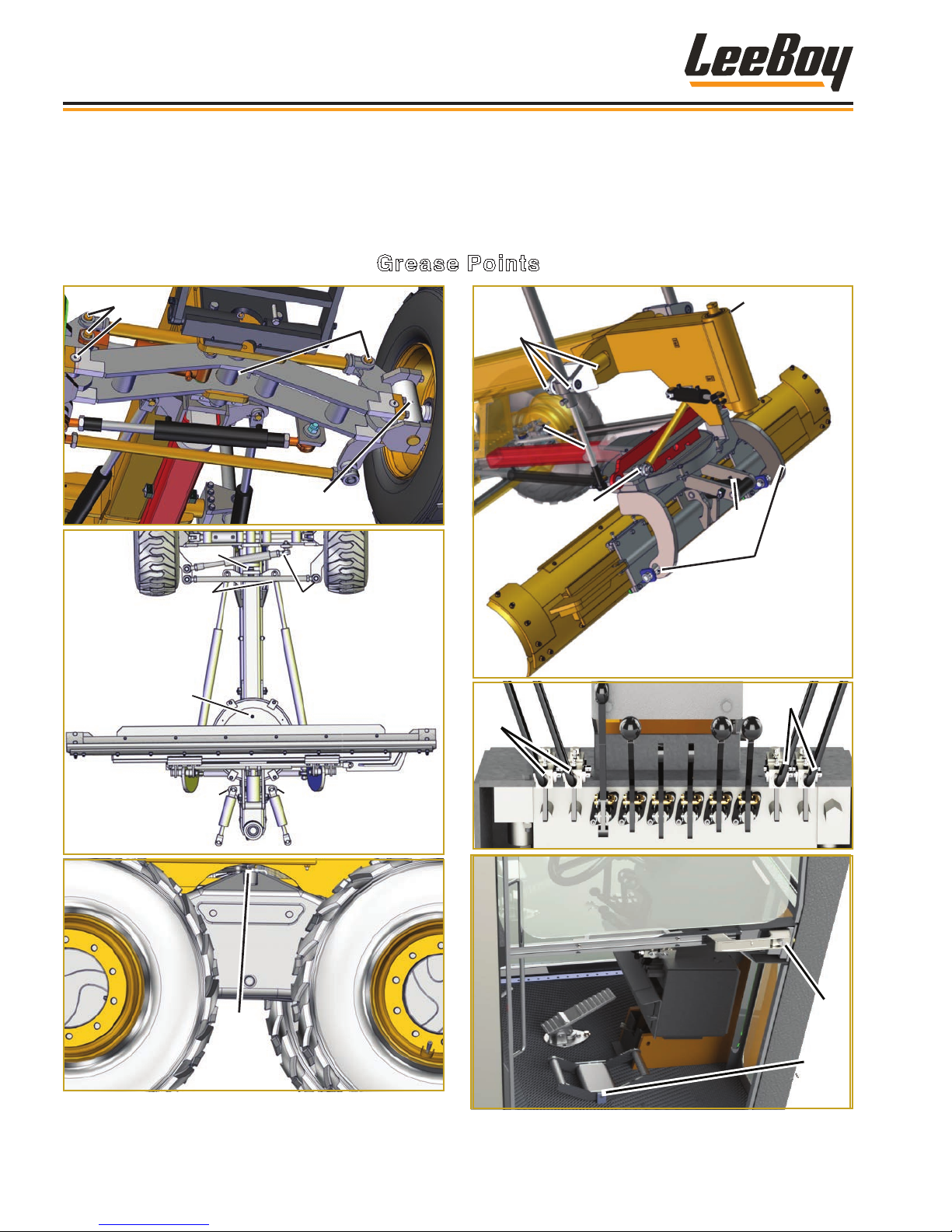
12
8
15
15
Maintenance
LUBRICATION
Proper lubrication is very important for maintaining the machine at top efciency. Use multi-purpose grease to
lubricate the grease points shown below. Additional lubrication requirements are described on the following pages.
Grease Points
1
1
9
10
2
11
13
3
14
5
6
4
7
7
16
17
LeeBoy 685D Motor Grader5-6
Page 99
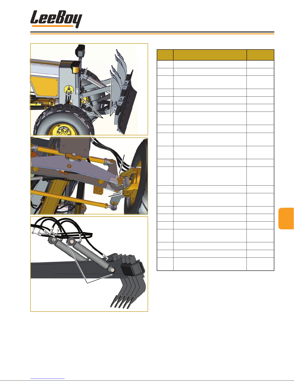
Maintenance
Table 5-2. Lubrication Points
No. ITEM INTERVAL
18
19
20
20
1 Front Axle Joints (both sides) Weekly
2 Front King Pins (both sides) Monthly
Drawbar Ball (until grease es-
3
capes from the ball joint)
4 Steering Cylinders and Tie Rod Daily
5 Moldboard Swing Cylinders Daily
6 Turntable (4 grease ttings) Weekly
Articulated Cylinder (until grease
7
escapes from clevis pin joints)
8
Rear Axle
Moldboard Lift Trunnion (both
9
sides)
Moldboard Lift Cylinders (both
10
sides)
11 Moldboard Stabilizer Weekly
Articulated Joint (until grease
12
escapes from the upper and
lower joints)
13 Moldboard Tilt Cylinder Weekly
Moldboard Mounting Pins (both
14
sides)
15 Valve Handles Monthly
16 Door Handle Monthly
17 FNR Pedal Weekly
Front Blade/Scarier Lift Cylinder
18 **
(See Below)
19 ** Front Blade Joints Weekly
20 ** AWD Front King Pins (both sides) Weekly
Rear Scarier Lift Cylinders (both
21 **
sides)
* (6 on each side)
Daily
Weekly
Monthly
Daily
Daily
Monthly
Weekly
Weekly
Weekly
5
21
LeeBoy 685D Motor Grader 5-7
* Not all grease ttings are shown on rear axle
graphic. Be sure to look closely and grease all
ttings on inside of tandems at the pivot point (6 on
each side of axle.
** OPTION. Only applicable if equipped with options
as shown:
Page 100
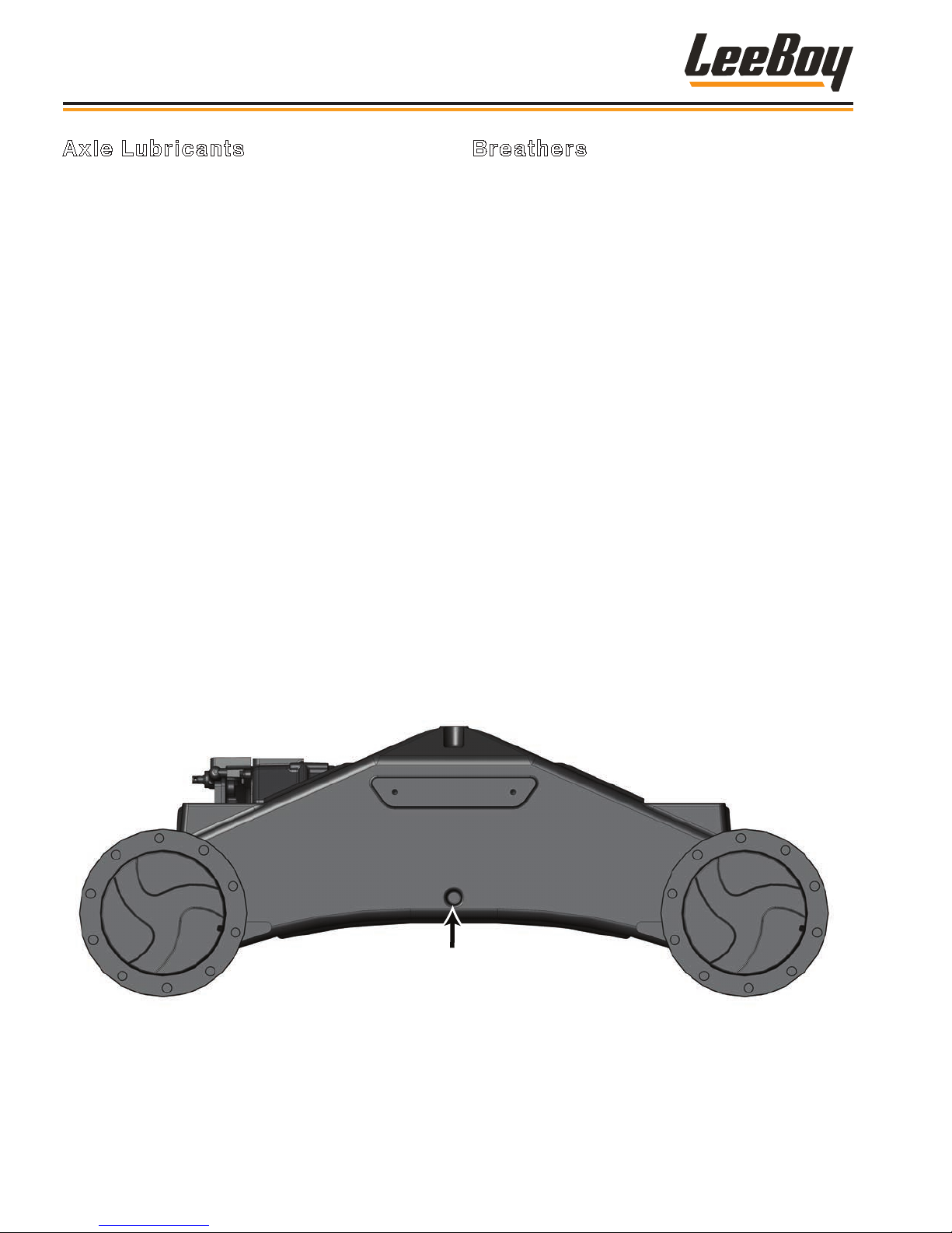
Maintenance
Axle Lubricants
Check the gear box, tandem box, axle and hydraulic
motor oil levels quarterly, shown in Figures 5-1 and
5-2). Add more gear oil if needed. Change the oil on
these components every year for optimum performance.
NOTE: The manufacturer recommens axle lubricant
that meets API GL-5/MT-1 or SAE J2360
specication.
Use the following procedure to change oil at the various
oil plug points as shown:
1. Park machine on level ground.
2. Remove the oil plug(s) shown in Figures 5-1 and
5-2.
3. Add oil until it starts coming out of the level plug.
4. Replace the level plug.
5. Allow the axle to sit level for at least ve minutes to
allow the oil to ow throughout components.
6. Remove the level plug and check oil level.
7. Add more oil if needed.
Breathers
Hydraulic gear boxes, axles, pumps and tanks need to
“breathe” as air is drawn in when hydraulic components
activate. Breathers stop water, dirt and debris from
contaminating the oil. If the breathers are clogged, the
resulting heat and pressure increase will force lubricant
to escape through seals and joints in the housing,
leading to bearing or gear failure. To prolong the
operational life of a bogie axle, regular inspections and
maintenance of the breathers is essential. (Figure 5-2)
• Always inspect the breathers when checking oil levels.
Simply dusting and brushing off the gear breathers
regularly will keep out dirt and debris that can clog the
breathers.
• Check for oil leaks. Leaks indicate that seals
have failed, thus allowing dust, debris and water to
contaminate the oil.
• If the breathers and/or seals are damaged, they
should be replaced without delay to prevent internal
contamination and inadequate lubrication.
• To replace, simply unscrew the breather and discard,
then reinstall the new breather.
Side View
Tandem Oil
Level Plug
Figure 5-1. Side View of Bogie Axle
LeeBoy 685D Motor Grader5-8
 Loading...