

LeeBoy 400T, 400 User Manual

Operations, Service, and Parts Manual
400 T
LeeBoy Model 400 & 400T Rollers
Manual No. 1012791-01
This manual applies to
Serial Number 400-41197
and above
400

LeeBoy Model 400 & 400T Rollersii
Thumb Index
Safety
Information and Specifications
Component Location
Operation
Maintenance
1
2
3
4
5
Schematics
Illustrated Parts List (IPL)
6
7
DISCLAIMER AND COPYRIGHT
Disclaimer:
All information, illustrations and specications in this manual are based on the latest information available at the time
of publishing. The illustrations used in this manual are intended as representative reference views only. Moreover,
because of our continuous product improvement policy, we may modify information, illustrations and/or specications
to explain and/or exemplify a product, service or maintenance improvement. We reserve the right to make any
change at any time without notice. VT LeeBoy, Inc., VT LeeBoy, LeeBoy, and Rosco are all the same entity and are
used interchangeably.
©2015 VT LeeBoy, Inc.
LeeBoy reserves all copyright and other rights in this manual and the manual’s content. No part of this manual may
be reproduced or used in any way without the written permission of LeeBoy, except as necessary to operate LeeBoy
equipment.
California Proposition 65 WARNING
Diesel engine exhaust and some of its constituents are known to the State of California to cause cancer, birth
defects, and other reproductive harm.
Battery posts, terminals and other related accessories contain lead and lead compounds, chemicals known to the
State of California to cause cancer and other reproductive harm. Wash hands after handling.
LeeBoy Model 400 & 400T Rollersiv

TABLE OF CONTENTS
Page
Introduction . . . . . . . . . . . . . . . . . . . . . . . . . . . . . . . . .ix
Safety . . . . . . . . . . . . . . . . . . . . . . . . . . . . . . . . . . . 1-1
Safety Precautions . . . . . . . . . . . . . . . . . . . . . . . . . . . . . 1-4
Pre-Operation Hazard . . . . . . . . . . . . . . . . . . . . . . . . 1-4
Safety Label Locations . . . . . . . . . . . . . . . . . . . . . . . . . . . 1-7
Safety Decals Care . . . . . . . . . . . . . . . . . . . . . . . . . 1-8
Machine Specic Precautions . . . . . . . . . . . . . . . . . . . . . . . 1-8
Hot Material Precautions . . . . . . . . . . . . . . . . . . . . . . . 1-8
Hydraulic Systems Precautions . . . . . . . . . . . . . . . . . . . 1-8
Refueling Precautions . . . . . . . . . . . . . . . . . . . . . . . . 1-9
Battery Precautions . . . . . . . . . . . . . . . . . . . . . . . . . 1-9
Tire Precautions . . . . . . . . . . . . . . . . . . . . . . . . . . . 1-9
Starting and Stopping Precautions . . . . . . . . . . . . . . . . . . 1-10
Parking Precautions . . . . . . . . . . . . . . . . . . . . . . . . . 1-10
Operating Precautions . . . . . . . . . . . . . . . . . . . . . . . . 1-10
Storage Precautions . . . . . . . . . . . . . . . . . . . . . . . . . 1-11
Maintenance Precautions . . . . . . . . . . . . . . . . . . . . . . 1-11
Information and Specications . . . . . . . . . . . . . . . . . . . . . . . . 2-1
Limited Warranty Policy . . . . . . . . . . . . . . . . . . . . . . . . . . 2-2
Contact Information . . . . . . . . . . . . . . . . . . . . . . . . . . . . 2-3
Record of Ownership . . . . . . . . . . . . . . . . . . . . . . . . . . . 2-3
Nameplate . . . . . . . . . . . . . . . . . . . . . . . . . . . . . . . . . 2-3
Specications Charts. . . . . . . . . . . . . . . . . . . . . . . . . . . . 2-4
Torque Specications . . . . . . . . . . . . . . . . . . . . . . . . . . . 2-6
Standard Inch Fasteners . . . . . . . . . . . . . . . . . . . . . . . 2-6
Metric Fasteners . . . . . . . . . . . . . . . . . . . . . . . . . . . 2-7
Hydraulic Fittings . . . . . . . . . . . . . . . . . . . . . . . . . . 2-7
Determining Proper Torque . . . . . . . . . . . . . . . . . . . . . 2-8
LeeBoy Model 400 & 400T Rollers v

Component Location . . . . . . . . . . . . . . . . . . . . . . . . . . . . . 3-1
Operator’s Control Console . . . . . . . . . . . . . . . . . . . . . . . . 3-3
Location of Operation Panels and Controls . . . . . . . . . . . . . . . . . 3-4
Hydraulic Levers (400T ONLY) . . . . . . . . . . . . . . . . . . . . . . . 3-6
Operation . . . . . . . . . . . . . . . . . . . . . . . . . . . . . . . . . . 4-1
General Information . . . . . . . . . . . . . . . . . . . . . . . . . . . . 4-3
Operating Safety . . . . . . . . . . . . . . . . . . . . . . . . . . . . . . 4-3
Parking Safety . . . . . . . . . . . . . . . . . . . . . . . . . . . . 4-4
Maintenance Safety . . . . . . . . . . . . . . . . . . . . . . . . . 4-4
Receiving the Roller . . . . . . . . . . . . . . . . . . . . . . . . . . . . 4-4
Preliminary Procedures . . . . . . . . . . . . . . . . . . . . . . . . . . 4-5
Adjusting Operator Seat . . . . . . . . . . . . . . . . . . . . . . . 4-5
Beacon Light . . . . . . . . . . . . . . . . . . . . . . . . . . . . 4-5
Pre-Start . . . . . . . . . . . . . . . . . . . . . . . . . . . . . . . . . 4-5
Machine Operation . . . . . . . . . . . . . . . . . . . . . . . . . . . . . 4-6
Engine Start-Up . . . . . . . . . . . . . . . . . . . . . . . . . . . 4-6
Engine Warm-Up . . . . . . . . . . . . . . . . . . . . . . . . . . 4-6
Cold Weather Engine Warm-Up . . . . . . . . . . . . . . . . . . . 4-6
Directional Control . . . . . . . . . . . . . . . . . . . . . . . . . 4-6
Braking . . . . . . . . . . . . . . . . . . . . . . . . . . . . . . . 4-7
Vibratory Compactor . . . . . . . . . . . . . . . . . . . . . . . . . 4-7
Water Spray System . . . . . . . . . . . . . . . . . . . . . . . . . 4-7
Principles of Compaction . . . . . . . . . . . . . . . . . . . . . . . . . . 4-8
Rolling Techniques . . . . . . . . . . . . . . . . . . . . . . . . . . . . . 4-8
Rolling Pattern . . . . . . . . . . . . . . . . . . . . . . . . . . . . 4-9
Rolling Thick Lifts . . . . . . . . . . . . . . . . . . . . . . . . . . 4-9
Rolling Thin Lifts . . . . . . . . . . . . . . . . . . . . . . . . . . . 4-9
Parking the Machine . . . . . . . . . . . . . . . . . . . . . . . . . 4-10
Transporting the Roller . . . . . . . . . . . . . . . . . . . . . . . . . . . 4-10
Roller Towing (400T Only) . . . . . . . . . . . . . . . . . . . . . . 4-10
Transporting Via Flatbed . . . . . . . . . . . . . . . . . . . . . . 4-12
Maintenance . . . . . . . . . . . . . . . . . . . . . . . . . . . . . . . . . 5-1
General Information . . . . . . . . . . . . . . . . . . . . . . . . . . . . 5-3
Lubrication Points . . . . . . . . . . . . . . . . . . . . . . . . . . . . . 5-4
Maintenance Schedule . . . . . . . . . . . . . . . . . . . . . . . . . . 5-5
Preparing Machine for Maintenance . . . . . . . . . . . . . . . . . 5-6
10-Hour or Daily Routine Maintenance . . . . . . . . . . . . . . . . 5-6
vi
LeeBoy Model 400 & 400T Rollers

50-Hour or Weekly Routine Maintenance . . . . . . . . . . . . . . 5-6
100-Hour or Monthly Routine Maintenance . . . . . . . . . . . . . . 5-6
250-Hour or Quarterly Routine Maintenance . . . . . . . . . . . . . 5-6
500-Hour or Semi-Annual Routine Maintenance . . . . . . . . . . . 5-7
1000-Hour or Annual Routine Maintenance . . . . . . . . . . . . . 5-7
Maintenance Adjustments . . . . . . . . . . . . . . . . . . . . . . . . . 5-7
Water Spray System . . . . . . . . . . . . . . . . . . . . . . . . . 5-7
Parking Brake . . . . . . . . . . . . . . . . . . . . . . . . . . . . 5-8
Oil Lines and Fittings . . . . . . . . . . . . . . . . . . . . . . . . 5-8
Air Intake Hoses . . . . . . . . . . . . . . . . . . . . . . . . . . . 5-8
Drive Belt . . . . . . . . . . . . . . . . . . . . . . . . . . . . . . 5-8
Neutral Start System . . . . . . . . . . . . . . . . . . . . . . . . 5-8
Electrical System . . . . . . . . . . . . . . . . . . . . . . . . . . . . . . 5-9
Battery Servicing . . . . . . . . . . . . . . . . . . . . . . . . . . . 5-9
Battery Maintenance . . . . . . . . . . . . . . . . . . . . . . . . . 5-9
Check Battery Electrolyte Level . . . . . . . . . . . . . . . . . . . 5-10
Alternator . . . . . . . . . . . . . . . . . . . . . . . . . . . . . . 5-10
Cold Weather Starting . . . . . . . . . . . . . . . . . . . . . . . . 5-10
Fuses And Circuit Breakers . . . . . . . . . . . . . . . . . . . . . 5-10
Tire Maintenance . . . . . . . . . . . . . . . . . . . . . . . . . . . . . 5-11
Filling Tires with Air . . . . . . . . . . . . . . . . . . . . . . . . . 5-11
Changing Tires . . . . . . . . . . . . . . . . . . . . . . . . . . . 5-11
Engine Maintenance . . . . . . . . . . . . . . . . . . . . . . . . . . . . 5-12
Check Engine Lubrication Oil Level . . . . . . . . . . . . . . . . . 5-12
Changing Engine Lubrication Oil . . . . . . . . . . . . . . . . . . . 5-12
Change Engine Oil Filter . . . . . . . . . . . . . . . . . . . . . . . 5-13
Change Engine Air Filter . . . . . . . . . . . . . . . . . . . . . . . 5-13
Fuel System . . . . . . . . . . . . . . . . . . . . . . . . . . . . . . . . 5-14
Fuel Tank . . . . . . . . . . . . . . . . . . . . . . . . . . . . . . 5-14
Engine Fuel Filters . . . . . . . . . . . . . . . . . . . . . . . . . . 5-14
Hydraulic System . . . . . . . . . . . . . . . . . . . . . . . . . . . . . 5-15
Checking Hydraulic Oil Level . . . . . . . . . . . . . . . . . . . . 5-15
Change Hydraulic Filter . . . . . . . . . . . . . . . . . . . . . . . 5-16
Check and Clean Hydraulic Oil Strainer Fill Cap . . . . . . . . . . . 5-16
Drain, Flush and Fill Hydraulic Oil Tank . . . . . . . . . . . . . . . . 5-17
Component Replacement Procedures . . . . . . . . . . . . . . . . . . . 5-17
LeeBoy Model 400 & 400T Rollers
vii

Introduction
Storage . . . . . . . . . . . . . . . . . . . . . . . . . . . . . . . . . . 5-19
Troubleshooting . . . . . . . . . . . . . . . . . . . . . . . . . . . . . . 5-20
Schematics . . . . . . . . . . . . . . . . . . . . . . . . . . . . . . . . . 6-1
Electrical Schematic, Tow Pak, 400T . . . . . . . . . . . . . . . . . . . . 6-3
Panel, Gauges, Kubota, 400 . . . . . . . . . . . . . . . . . . . . . . . . 6-5
Electrical Schematic, Option, 400 / 400T . . . . . . . . . . . . . . . . . . 6-7
Hydraulic Hose Layout, 400, 1 of 2 . . . . . . . . . . . . . . . . . . . . . 6-9
Hydraulic Hose Layout, 400, 2 of 2 . . . . . . . . . . . . . . . . . . . . . 6-11
Illustrated Parts List . . . . . . . . . . . . . . . . . . . . . . . . . . . . . 7-1
Quick Reference Guide . . . . . . . . . . . . . . . . . . . . . . . . . . 7-3
400 Main Frame Assembly, 1 of 2 . . . . . . . . . . . . . . . . . . . . . 7-4
400 Main Frame Assembly, 2 of 2 . . . . . . . . . . . . . . . . . . . . . 7-6
Replace Batteries . . . . . . . . . . . . . . . . . . . . . . . . . . 5-17
Replace Valve Bank Assembly (400T Only) . . . . . . . . . . . . . . 5-18
Water Tank and Rollbar Groups . . . . . . . . . . . . . . . . . . . . . . 7-8
Front Drum and Yoke Assembly . . . . . . . . . . . . . . . . . . . . . . 7-10
Front Wiper, Front Inner Wiper, and Rear Wiper, 400 / 400T . . . . . . . . 7-12
Rear Drum Assembly, Cut-Section . . . . . . . . . . . . . . . . . . . . . 7-14
Water System Assembly . . . . . . . . . . . . . . . . . . . . . . . . . . 7-16
Fuel System Group . . . . . . . . . . . . . . . . . . . . . . . . . . . . 7-18
Steering and Drive Control Assembly . . . . . . . . . . . . . . . . . . . 7-20
Seat Assembly . . . . . . . . . . . . . . . . . . . . . . . . . . . . . . . 7-22
Engine Group, 1 of 2 . . . . . . . . . . . . . . . . . . . . . . . . . . . . 7-24
Engine Group, 2 of 2 . . . . . . . . . . . . . . . . . . . . . . . . . . . . 7-26
25 HP, Tier4F, Engine, Kubota . . . . . . . . . . . . . . . . . . . . . . . 7-28
Battery Group . . . . . . . . . . . . . . . . . . . . . . . . . . . . . . . 7-30
400 and 400T Miscellaneous . . . . . . . . . . . . . . . . . . . . . . . 7-32
Sign (Option) . . . . . . . . . . . . . . . . . . . . . . . . . . . . . . . . 7-34
400T Main Frame Assembly . . . . . . . . . . . . . . . . . . . . . . . . 7-36
Tow/Lift Group . . . . . . . . . . . . . . . . . . . . . . . . . . . . . . . 7-38
400T Towing Safety Pin and Pintle Eye . . . . . . . . . . . . . . . . . . . 7-40
viii
Wheel Hub and Brake Assembly . . . . . . . . . . . . . . . . . . . . . . 7-42
Valve Bank Assembly (400T Only) . . . . . . . . . . . . . . . . . . . . . 7-44
Alphabetical Parts Index (API) . . . . . . . . . . . . . . . . . . . . . . . 7-46
LeeBoy Model 400 & 400T Rollers

INTRODUCTION
Thank you for purchasing the 400 or the 400T Roller.
We wish you many years of safe and efcient operation
of your roller.
READ THIS MANUAL PRIOR TO OPERATING the unit.
This manual is an important part of the roller and should
be kept with the roller at all times in the dedicated
storage container on the roller. Even though you may
be familiar with similar equipment, you MUST read and
understand this manual before operating this roller.
Reading the manual will help you and others avoid
injury and prevent damage to the roller. If this manual
becomes lost or damaged, contact your authorized
LeeBoy Dealer immediately to order a replacement
(Contact Information on Page 2-3).
This manual is intended as a guide for the safe and
efcient use of the roller. This manual contains
procedures for proper operation and maintenance of
the roller. This manual contains information that was
available at the time of printing and is subject to change
without notice.
This manual should be used along with all related
supplemental books, engine and transmission manuals,
and parts books. Related Service Bulletins may be
issued later that provide information regarding any
recent changes.
If any questions arise concerning this publication or
others, contact your local LeeBoy Dealer for the latest
available information.
LeeBoy Model 400 & 400T Rollers
ix

NOTES
x
LeeBoy Model 400 & 400T Rollers

Section 1
SAFETY
Page
Safety Precautions . . . . . . . . . . . . . . . . . . . . . . . . . . . . . 1-4
Pre-Operation Hazard . . . . . . . . . . . . . . . . . . . . . . . . 1-4
Safety Label Locations . . . . . . . . . . . . . . . . . . . . . . . . . . . 1-7
Safety Decals Care . . . . . . . . . . . . . . . . . . . . . . . . . 1-8
Machine Specic Precautions . . . . . . . . . . . . . . . . . . . . . . . 1-8
Hot Material Precautions . . . . . . . . . . . . . . . . . . . . . . . 1-8
Hydraulic Systems Precautions . . . . . . . . . . . . . . . . . . . 1-8
Refueling Precautions . . . . . . . . . . . . . . . . . . . . . . . . 1-9
Battery Precautions . . . . . . . . . . . . . . . . . . . . . . . . . 1-9
Tire Precautions . . . . . . . . . . . . . . . . . . . . . . . . . . . 1-9
Starting and Stopping Precautions . . . . . . . . . . . . . . . . . . 1-10
Parking Precautions . . . . . . . . . . . . . . . . . . . . . . . . . 1-10
Operating Precautions . . . . . . . . . . . . . . . . . . . . . . . . 1-10
Storage Precautions . . . . . . . . . . . . . . . . . . . . . . . . . 1-11
Maintenance Precautions . . . . . . . . . . . . . . . . . . . . . . 1-11
LeeBoy Model 400 & 400T Rollers
1-1

Safety
NOTES
LeeBoy Model 400 & 400T Rollers1-2

Safety
This manual provides important information to familiarize
you with safe operating and maintenance procedures.
Even though you may be familiar with similar equipment,
you MUST read and understand this manual before
operating the LeeBoy Model 400 or 400T Roller and
follow its instructions when operating the machine.
Safety is everyone’s business and our top concern.
Knowing the guidelines covered in this section will help
ensure your safety, the safety of those around you,
proper machine operation.
Keep safety labels in good condition. If safety
labels become missing or damaged, replace them
immediately. Replacement safety labels are available
from your authorized dealer. .
LOOK FOR THESE SYMBOLS THROUGHOUT
THIS MANUAL. THESE ITEMS ARE EXTREMELY
IMPORTANT FOR THE SAFETY OF YOU AND
YOUR COWORKERS. READ AND UNDERSTAND
THOROUGHLY. HEED THE WARNINGS AND
FOLLOW THE INSTRUCTIONS.
Indicates a hazardous situation which,
if not avoided, will result in death or serious injury.
Indicates a hazardous situation which,
if not avoided, could result in death or serious injury.
Indicates a hazardous situation which,
if not avoided, could result in minor or moderate
injury.
Indicates a situation which can cause
damage to the equipment, personal property and/
or the environment, or cause the LeeBoy Model 400
and 400T to operate improperly.
1
NOTE: Indicates a procedure, practice or condition
that should be followed in order for the roller
components to function properly.
LeeBoy Model 400 & 400T Rollers 1-3

Safety
SAFETY PRECAUTIONS
Pre-Operation Hazard
Read and understand this Operation Manual
before operating or servicing the engine to
ensure that safe operating practices and
maintenance procedures are followed.
• Never permit anyone to service or operate the LeeBoy
machine without proper training.
The safety messages that follow have WARNING
level hazards.
Crush Hazard
Keep bystanders away from work area before and
during operation.
• Safety signs and labels are additional reminders for
safe operating and maintenance techniques.
• Contact LeeBoy or an authorized LeeBoy Dealer for
additional training.
• Make sure you are aware of all laws and regulations
that are in effect for the location in which the roller is
operated.
• Make sure you have all necessary licenses to operate
the roller.
Indicates a hazardous situation which, if not avoided,
will result in death or serious injury.
Electrocution Hazard
If your machine comes into contact with electric
power lines, observe the following:
• Stay in the operators seat.
• Warn other workers to stay away and do not touch any
control or any part of the machine.
• If contact can be broken, drive the machine away from
the danger zone.
• If contact cannot be broken, stay in the operators seat
until told that power is off.
Modification Hazard
Never modify the LeeBoy machine without written
consent of LeeBoy. Any modication can affect the safe
operation of the roller and may cause personal injury or
death.
Exposure Hazard
Always wear personal protective equipment,
including appropriate clothing, gloves, work
shoes, and protection for eyes and ears, as
required by the task at hand.
Explosion Hazard
While the engine is running or the battery is
charging, hydrogen gas is being produced
and can be easily ignited. Keep the area
around the battery well-ventilated and keep
sparks, open ame, and any other form of
ignition out of the area.
• Always disconnect the negative (-) battery cable
before servicing the roller.
• Do not start the engine by shorting the starter circuit
or any other starting method not stated in this manual.
Only use the starting procedure as described in this
manual on Page 4-6 to start the engine.
• Failure to observe these directions could result in
electrocution or death.
Suffocation Hazard
Never operate the internal combustion engine
on this machine in an enclosed area with poor
ventilation. Ensure proper ventillation to
reduce risk of carbon monoxide poisoning or death.
Fire and Explosion Hazard
• Diesel fuel is ammable and explosive under certain
conditions.
• Never use a shop rag to catch fuel.
• Wipe up all spills immediately.
• Never refuel with the engine running.
LeeBoy Model 400 & 400T Rollers1-4
Safety
• Store any containers containing fuel in a wellventilated area away from any combustibles or
sources of ignition.
Fire Hazard
Be sure appropriate safety equipment is
available. Ensure all re extinguishers are
checked periodically for proper operation.
• Keep a charged re extinguisher within reach when
working in an environment where a re may occur.
• Always read and follow safety-related precautions
found on containers of hazardous substances
like parts cleaners, primers, sealants and sealant
removers.
• Undersized wiring systems can cause electrical res.
Exhaust Hazard
All internal combustion engines create
carbon monoxide gas during operation and
special precautions are required to avoid
carbon monoxide poisoning:
• Never block windows, vents or other means of
ventilation.
• Verify that all guards and covers are properly attached
before starting the engine. Do not start the engine if
any guards or covers are not properly installed on the
roller.
• If you must run the engine during maintenance
procedures, make sure you have a helper to keep
bystanders clear of the roller and make observations
of moving parts as requested by the operator.
• Always turn the start switch to the OFF position after
operation is complete and remove the key from the
switch. Keep the key in your possession when the
roller is not operating.
• Attach a “Do Not Operate” tag near the key switch
while performing maintenance on the equipment.
• Never operate the engine while wearing a headset to
listen to music or radio because it will be difcult to
hear the warning signals.
• Always start the engine and operate the controls while
seated in the operators seat.
Alcohol and Drug Hazard
Never operate the machine while under the
inuence of alcohol, drugs, or when ill.
1
• Always ensure that all connections are tightened to
specications after repair is made to the exhaust
system.
Entanglement/Sever Hazard
Verify there are no people, obstacles or
other equipment near the machine before
starting the engine. Sound the horn as a
warning before starting the engine.
If the engine must be serviced while it is operating,
remove all jewelry and tie back long hair before
operating or servicing the machine.
• Keep hands, other body parts, and clothing away
from moving/rotating parts.
• Always stop the engine before beginning service.
Before maintenance, remove negative battery cable
from battery post to ensure vehicle is not operated
during maintenance.
Piercing Hazard
High-pressure hydraulic uid or fuel can
penetrate your skin and result in serious
injury. Avoid skin contact with high-pressure
hydraulic uid or diesel fuel spray caused by
a hydraulic or fuel system leak such as a broken
hydraulic hose or fuel injection line.
• If you are exposed to high-pressure hydraulic uid or
fuel spray, obtain prompt medical treatment.
• Never check for a hydraulic uid or fuel leak with your
hands. Always use a piece of wood or cardboard.
Have your authorized LeeBoy Dealer or distributor
repair the damaged parts.
LeeBoy Model 400 & 400T Rollers 1-5
Safety
Flying Object Hazard
Always wear eye protection when cleaning
the LeeBoy Model 400 or 400T Roller
with compressed air or high-pressure
water. Dust, ying debris, compressed air,
pressurized water or steam may cause eye
injury.
Coolant Hazard
Wear eye protection and rubber gloves
when handling engine coolant.
• If contact with the eyes occurs, ush eyes with clean
water for 15 minutes.
• If contact with skin occurs, wash immediately with
soap and clean water.
Burn Hazard
Some of the machine’s surfaces become
very hot during operation and shortly after
shutdown.
The safety messages that follow have NOTICE level
hazards.
• Any part found defective during inspection or does not
satisfy the proper standard or limit must be replaced.
• Always tighten components to the specied torque.
Loose parts can cause damage to the LeeBoy
machine or cause it to operate improperly.
• Only use replacement parts approved by LeeBoy.
Other replacement parts may affect warranty
coverage.
Follow the guidelines of the EPA or
other governmental agencies for the
proper disposal of hazardous materials
such as engine oil, diesel fuel, and
engine coolant. Consult the local
authorities or reclamation facility.
• Dispose of hazardous materials in accordance with
all applicable laws and regulations. Never dispose of
hazardous materials by dumping them into a sewer, on
the ground, or into groundwater or waterways.
• Keep hands and other body parts away from hot
machine surfaces.
• Handle hot components with heat-resistant gloves.
The safety messages that follow have CAUTION level
hazards.
Poor Lighting Hazard
• Ensure that the work area is adequately illuminated.
• Always install wire cages on portable safety lights.
Tool Hazard
Always use tools appropriate for the task at hand and
use the correct size tool for loosening or tightening
LeeBoy machine parts.
• Clean all accumulated dirt and debris away from the
body of the roller and its components before you
inspect the roller or perform preventive maintenance
procedures or repairs. Operating a roller with
accumulated dirt and debris will cause premature
wear of roller components. Accumulated dirt and
debris also hinders effective roller inspection.
• Retrieve any tools or parts that may have dropped
inside of the roller to avoid improper roller operation.
• If any alert indicator illuminates during roller operation,
stop the engine immediately. Determine the cause
and repair the problem before continuing to operate
the roller.
LeeBoy Model 400 & 400T Rollers1-6
(Under water tank)
565 9
D ANG E R
or roll over p ote ti on, tank
MUS T be bolte d down .
Fa ilur e to co mply wil l re su lt in
deat h or s erio us in j r y.
1010489
PINCH POINT
PUNTO DE APRIETE
POINT DE PINCEMENT
DA NG E R
P EL IG R O
DA NG E R
D
856542
DA NG E R
FLAMMABLE – KEEP CLEAN
856529
CRUSH HAZARD!
K eep cle ar of m ach ine.
Fa ilur e to co mply wil l re su lt in
dea th or s eri ous in jury.
D ANG E R
1011475
WAR NI NG
DO NOT TOW OVER 45 MPH.
DO NOT TOW OVER 45 MPH.
856558-01
RUN-AWAY VEHICLE
HAZARD!
Machine mu st be i n
NEUT R AL an d E mer gen cy
Brak e a pplie d be fore
dismou nting .
Failur e to co mply wil l re su lt
in death or s erio us inj ury.
DAN GE R
856539
Do not oper ate or tow u nit b efor e re adi ng
operato rs ma nual .
Failu re to c omply c ould re su lt in dea th o r
serio us in jury.
WA R NING
No us ar ni r emol ca r la má quin a s in ante s hab er
leído el ma nual del ope rad or.
Si no s e c umpl e c on es ta d isp os ici ón, s e pu ede
caus ar la m uerte o les ion es gra ves .
AD VE R TE N CIA
Ne pas fa ire fon ctio nner ni rem orqu er l a
machin e av ant de lire le manu el d ’op érati ons .
Le non -res pe ct d e c ette règl e ri sq ue d ’en traîn er
des bl es su res g rav es , v oire mor telle s.
AV ER T IS S EM EN T
856446
Hydr aul ic oil only
Ke ep c lea n
Huil e hy dra uliq ue
se ulem ent
Main tenir pro pre
P RE C A UC ION
ATT E NT ION
Ac eite hidr áuli co s olam ente
Mante ner limp io
C AU TIO N
856526
DO NOT s tand or s tep h ere
when mac hin e is movi ng.
Fai lure to com ply will
res ult in d eath or s erio us
injur y.
D ANG E R
856528
WA R NING
RUN-AWAY
VEHICLE
HAZARD!
DO NOT
attemp t to
dis co nnec t
roll er f rom
hitc h wh en
tow w heel s are
on g rou nd.
Fai lure to
com ply cou ld
res ult in d eath
or s er iou s
injur y.
(On engine)
Safety
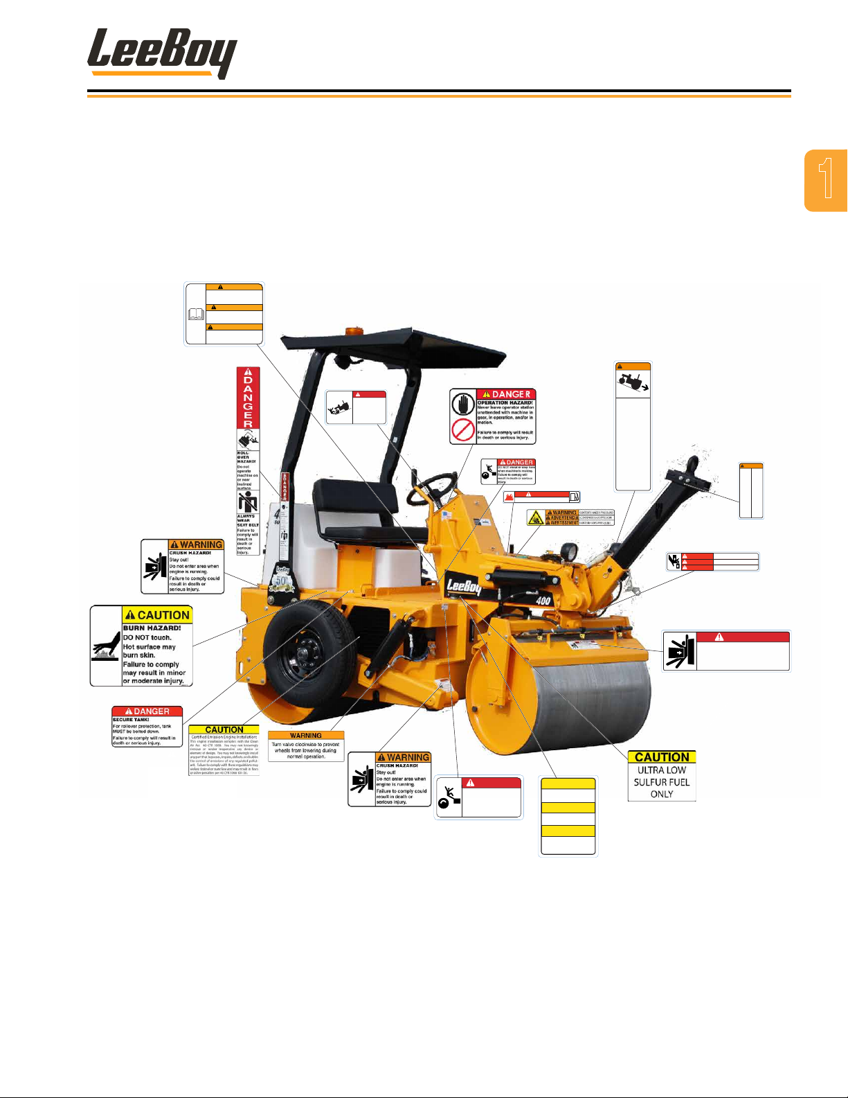
SAFETY LABEL LOCATIONS
If your LeeBoy machine has been repainted, it is
extremely important that all decals referring to
CAUTION, WARNING, and DANGER be replaced in their
proper locations. The illustrations on this page will aid
you in determining the proper locations. For additional
help, refer to Section 7, Illustrated Parts List.
A description of location is provided below for each
safety label. For additional instructions, contact your
dealer.
NOTE: It is the responsibility of the owner and
operator to make sure that all safety labels
are readable and located on roller as
designated by LeeBoy.
1
Figure 1-1. Safety Labels and Safety Label Locations
LeeBoy Model 400 & 400T Rollers 1-7
Safety
Safety Decals Care
• Keep safety decals and signs clean and legible at all
times.
• Become familiar with the content and position of each
safety decal. Decals include important information.
• Replace decals and signs that are missing or become
illegible.
• When replacing parts that display a safety decal,
ensure the new part is also tted with the correct
safety decal.
• Obtain safety decals or signs from your authorized
LeeBoy dealer when needed.
Decal Installation (Sticker Type)
1. Be sure the installation area is clean and dry. Use
hot, soapy water to clean the surface where decal
will be applied. Thoroughly dry.
2. Measure and determine decal positioning before
removing the decal paper backing.
3. Remove the smallest adhesive backing of the split-
backing paper.
4. Align decal over the specied area and carefully
press exposed portion into place.
5. Slowly remove the remaining backing and carefully
smooth the remaining portion of the decal into place.
6. Small air pockets can be pierced with a pin and
smoothed using a piece of the decal backing.
MACHINE SPECIFIC PRECAUTIONS
Hot Material Precautions
• Wear protective gear for face, hands and feet when
operating the roller.
• Allow machine to cool before repairing or performing
maintenance on working components.
If hot asphalt touches skin, ush area
immediately with cold water. DO NOT apply ice
to the affected area. DO NOT attempt to remove
asphalt cement with products containing solvents or
ammonia. Get medical attention as soon as possible.
DO NOT remove radiator cap, drain
plugs, and service grease ttings or pressure taps
when engine is hot. Add coolant to the radiator and
perform other services only when the engine is
stopped and fully cooled.
Hydraulic Systems Precautions
• Make sure all components are in good working
condition. Replace any worn, cut, abraded, attened
or crimped hoses and metal lines.
DO NOT attempt makeshift repairs
using tape, clamps or cements. The hydraulic
system operates under extremely high pressure and
such repairs could cause serious injury.
Decal Installation (Top Protected)
1. Be sure the installation area is clean and dry. Use
hot, soapy water to clean the surface where decal
will be applied. Leave wet.
2. Measure and determine decal positioning. Remove
protective backing and soak the decal in clean,
soapy water before application. (This will help to
alleviate air bubbles when applying the decal.)
3. Smooth the decal into place with a squeegee and
check for air bubbles.
4. Small air pockets can be pierced with a pin and
smoothed using a piece of the decal backing.
5. When the decal is completely smooth, carefully
remove the top paper.
Wear proper hand and eye protection
when searching for a high pressure leak. Use a
piece of wood or cardboard as a back stop (instead
of hands) to isolate and identify leaks. Pressurized
hydraulic uid or oil has sufcient force when it
escapes to penetrate the skin, which could cause
serious personal injury. Ensure pressure is relieved
before disconnecting line, hoses and valves.
If injured by concentrated high
pressure steam or hydraulic uid, seek medical
attention immediately. Serious infections or
toxic reactions can develop from hydraulic uid
penetrating the skin’s surface.
LeeBoy Model 400 & 400T Rollers1-8
Safety
Refueling Precautions
• Fuel is highly ammable and should be handled with
care. Death or serious injury can occur due to an
explosion or re.
• When refueling, keep the hose nozzle or the funnel
in contact with the metal of the fuel tank to avoid the
possibility of an electrical spark lighting the fuel.
Maintain control of ller nozzle.
• DO NOT ll tank to capacity. Allow room for expansion
to reduce the risk of fuel expanding and spilling from
the tank.
• DO NOT overll the fuel tank as overow creates a re
hazard when spilled onto hot components.
DO NOT smoke when refueling and
never refuel when the engine is running.
• Tighten fuel cap securely. Should fuel cap be lost,
only replace it with an original manufacturer-approved
cap. Pressurization of the tank may result from use of
non-approved cap.
• Prevent res by keeping the machine clean of
accumulated debris, grease and spilled fuel.
• Use the correct fuel grade for the operating season.
Battery Precautions
Keep all sparks and ames away from
batteries. Gas emitted by electrolytes is explosive.
Acid propelled by an explosion can
cause blindness if it comes into contact with eyes.
ALWAYS wear safety glasses when working near
batteries.
• If you come into contact with battery electrolyte
solution, wash off immediately. Chemicals can cause
burns.
Tire Precautions
DO NOT mount or demount tires
without proper training. A violent explosion can
occur.
Follow all procedures and safety instructions. Wall
charts containing mounting and demounting instructions
for all rims are available through the United States
Department of Transportation (DOT), Washington, D.C.
When in doubt, contact a qualied
tire dealer or repair service to perform required tire
maintenance.
Inspection
• Clean rims and repaint to stop detrimental effects of
corrosion and facilitate checking and tire mounting.
• Be very careful to clean all dirt and rust from rims.
This is important for securing rims into the proper
position.
• Check rim components periodically for cracks.
Replace all cracked, badly worn, severely rusted, and
otherwise damaged components with new parts of the
same size and type. If you are not sure about proper
mating of tire and wheel parts, consult a wheel and rim
expert.
DO NOT attempt to rework, weld,
heat, or braze any rim components that are cracked,
broken or damaged. Replace damaged components
with new parts of the same size and type. Mixing
parts of one type with those of another is potentially
dangerous.
DO NOT reinate a at tire without
rst inspecting the tire, tube, ap, rim, and wheel
assembly for damage. Be sure parts are secured
before ination.
1
• Always disconnect the battery ground cable before
working on the electrical system to avoid injury from
sparks or short circuit.
• To avoid electrolyte loss, DO NOT tip batteries more
than 45 degrees.
• Use jumper cables ONLY as prescribed on Page
5-11. Improper use can result in battery explosion or
unexpected roller motion.
LeeBoy Model 400 & 400T Rollers 1-9
Demounting
• Do not attempt to demount a tire unless you have the
proper equipment and experience to do the job.
• Remove valve core to exhaust all air from tire.
ALWAYS exhaust all air from tire prior to removing
rim components or wheel components (such as nuts
or rim clamps). Check the valve stem by running a
piece of wire through the stem to make sure it is not
plugged.

Safety
Mounting and Inflation
• DO NOT inate a tire before all components are in
the proper position. Place tire in a safety cage and
inate to approximately 10 psi. Recheck components
for proper assembly. If improperly assembled, deate
and correct.
• Never hammer on a tire/rim assembly that is not fully
deated. If assembly is proper at 10 psi, continue to
inate to fully seat the tire beads, then completely
deate the tire to prevent localized overstretching
of the tube. Reinate to recommended operating
pressure.
• NEVER sit on or stand in front of a tire/rim assembly
during ination. Use a clip-on chuck and make sure
ination hose is long enough to stand to the side of the
tire while inating.
• DO NOT hammer components with steel hammers.
Use rubber, lead, plastic or brass-faced mallets to tap
components together.
Operation
DO NOT inate tires beyond the maximum
recommended ination pressure.
NEVER run a vehicle one single tire of a dual assembly
as the carrying capacity is dangerously exceeded and
can result in damage to the rim and tire
Mismatched rim parts are dangerous
and can cause severe injury.
• Latch seat belt (if equipped) and adjust to t snugly.
• Only start and operate the machine from the
operator’s seat. DO NOT bypass paver/nisher‘s
neutral-start system. If the system malfunctions, it
must be repaired.
enclosed area without proper ventillation. Exhaust
gasses are odorless and deadly.
DO NOT operate the engine in an
Parking Precautions
• Park roller on level ground whenever possible. On
grades, park machine with wheels securely blocked.
Always apply parking brake.
• Before leaving operator’s station:
1. Place left drive handle in neutral.
2. Turn off all accessories.
3. Set emergency brake.
4. Shut off engine.
• Always remove ignition key when leaving roller parked
or unattended.
Operating Precautions
• Always comply with local regulations regarding
moving equipment on public roads and highways.
Starting and Stopping Precautions
• Check all around the roller to make sure there are no
people working on the machine or in the path of the
machine before starting. DO NOT start until area is
clear. Death or serious injury can occur to bystanders
from being crushed under a moving machine.
Check brakes, steering and other
control devices in accordance with instructions
before starting. Be sure emergency brake is applied
and the left Drive Throttle is in neutral.
• Know and use the hand signals required for a
particular job. Know who has the responsibility for
signaling.
• Make sure all lights and reectors comply with state
and local regulations. Keep them clean and in good
working order so they can be seen clearly by all trafc.
DO NOT stand between the equipment
and the truck while the truck is being coupled with
the paver/nisher. Death or serious injury can result
from being crushed between the two machines. DO
NOT ride on attachments.
LeeBoy Model 400 & 400T Rollers1-10

Safety
Some work situations require more
attention to stopping distances, particularly when
going downhill. Steeper grades require longer
stopping distances. Familiarize yourself with
these variables so you can anticipate when longer
stopping distances are required.
• Check all gauges and warning instruments for proper
operation. If malfunctions are found, shut down the
machine and report the problem for resolution. If the
failure causes loss of steering control, loss of brake
control or loss of engine power, stop roller motion
as quickly as possible. Apply emergency brake and
keep the machine securely parked until the failure is
corrected or the machine can be safely towed.
• Drive the machine with care. Make sure speed is
compatible with conditions. Use caution on rough
ground, slopes and while turning.
• Be alert for hazards and obstructions such as ditches,
trees, cliffs, overhead power lines, and areas where
there is danger of a slide.
• Be aware and understand the job site trafc ow
patterns.
• Obey agmen, road signs and signals.
• Watch for bystanders. Never allow anyone to be
under the machine during operation. Never allow
anyone to reach into the machine during use.
• Operator must know how to use signaling devices
while on the road with the machine. Operator must
also understand which circumstances require use of
each light signal.
• When required, provide an escort for roading.
• DO NOT tow the Model 400 roller, except to remove
from road or load on a trailer. The Model 400T is
equipped for towing.
Maintenance Precautions
• DO NOT attempt repairs unless trained to do so.
Refer to manuals and experienced repair personnel
for help.
• Before conducting maintenance, securely block the
machine and any components that may fall. Block
any working components to prevent unexpected
movement while repairs are being made.
• Always wear safety glasses and other required safety
equipment when servicing or making repairs.
• Disconnect battery before working on the electrical
system.
• Avoid lubrication or mechanical adjustments while
the roller is in motion or while engine is operating. If
lubrication or mechanical adjustment is necessary:
1. Place left drive handle control in neutral.
2. Apply emergency brake.
3. Shut off engine.
4. Place equipment in a safe position.
5. Use extreme caution.
• Never make repairs on pressurized components such
as uid lines, the gas system or mechanical items until
the pressure has been relieved.
• When inating tires, use a self-attaching ination
chuck with remote shut-off.
• When servicing or replacing hardened pins, use a
brass drift or other suitable material between the
hammer and pin.
• Keep brake and steering systems in good operating
condition.
• Refer to Section 5, Maintenance, for more detailed
information.
1
Storage Precautions
• Store roller in an area away from human activity.
• Do not permit children to play on or around the stored
machine. Serious injury or death can occur from
improper/unauthorized use of the machine.
• Make sure the unit is stored on a surface that is rm,
level, and free of debris.
• Store the machine inside a building or cover securely
with a weatherproof tarpaulin.
LeeBoy Model 400 & 400T Rollers 1-11

Safety
NOTES
LeeBoy Model 400 & 400T Rollers1-12

Section 2
INFORMATION AND SPECIFICATIONS
Page
Limited Warranty Policy . . . . . . . . . . . . . . . . . . . . . . . . . . 2-2
Contact Information . . . . . . . . . . . . . . . . . . . . . . . . . . . . 2-3
Record of Ownership . . . . . . . . . . . . . . . . . . . . . . . . . . . 2-3
Nameplate . . . . . . . . . . . . . . . . . . . . . . . . . . . . . . . . . 2-3
Specications Charts. . . . . . . . . . . . . . . . . . . . . . . . . . . . 2-4
Torque Specications . . . . . . . . . . . . . . . . . . . . . . . . . . . 2-6
Standard Inch Fasteners . . . . . . . . . . . . . . . . . . . . . . . 2-6
Metric Fasteners . . . . . . . . . . . . . . . . . . . . . . . . . . . 2-7
Hydraulic Fittings . . . . . . . . . . . . . . . . . . . . . . . . . . 2-7
Determining Proper Torque . . . . . . . . . . . . . . . . . . . . . 2-8
LeeBoy Model 400 & 400T Rollers
2-1

Information and Specications
LIMITED WARRANTY POLICY
Warranty
Subject to the limitations, exclusions, and claims procedures set
forth herein, VT LeeBoy, Inc. warrants [to the rst retail purchaser]
that this product will be free from substantial defects in materials
and workmanship during the warranty period.
If a defect in material or workmanship is found, your authorized
LeeBoy Dealer is to be notied during the warranty period.
LeeBoy and its authorized Dealer will repair or replace any part or
component of the unit or part that fails to conform to the warranty
during the warranty period.
The warranty period will begin on the initial start-up, training and
delivery of the unit by the Dealer to the customer, and will expire
after twelve (12) months following the delivery of the product to the
rst retail purchaser. (See Dealer for additional warranty.)
Manufacturers’ Warranties: Engines are warranted by their
manufacturers and may have warranty coverage that differs from
that of LeeBoy. LeeBoy does not warrant any engine.
Replacement parts furnished by LeeBoy are covered for the
remainder of the warranty period applicable to the unit or
component in which such parts are installed.
LeeBoy has the right to repair any component or part before
replacing it with a new one.
All new replacement parts purchased by a LeeBoy Dealer will carry
a six-month warranty.
This Limited Warranty is governed by the laws of the State of North
Carolina.
THE FOREGOING WARRANTY IS EXCLUSIVE AND IN LIEU
OF ALL OTHER EXPRESSED, STATUTORY AND IMPLIED
WARRANTIES APPLICABLE TO UNITS, ENGINES, OR PARTS
INCLUDING WITHOUT LIMITATION, ALL IMPLIED WARRANTIES
OF MERCHANTABILITY OR FITNESS FOR ANY PARTICULAR USE
OR PURPOSE OR AGAINST INFRINGEMENT.
Items Not Covered
LeeBoy is not responsible for the following:
All used units or used parts of any kind.
Repairs due to normal wear and tear or brought about by abuse or
lack of maintenance of the Machine.
Attachments not manufactured or installed by LeeBoy.
Liability for incidental or consequential damages of any type
including, but not limited to, lost prots or expenses of acquiring
replacement equipment.
Limitations
VT LeeBoy , Inc. has no obligation for:
Any defects caused by misuse, misapplication, negligence, accident,
or failure to maintain or use in accordance with the most current
operating instructions.
Unauthorized alterations.
Defects or failures caused by any replacement parts or attachments
not manufactured by or approved by LeeBoy.
Failure to conduct normal maintenance and operating service
including, without limitation, providing lubricants, coolant, fuel, tuneups, inspections, or adjustments.
Unreasonable delay, as established by LeeBoy, in making the
applicable units or parts available upon notication of a service notice
ordered by same.
Warranty Responsibility: The warranty responsibility on all engines
rests with the manufacturer of the engine.
Warranty and Parts Support: LeeBoy may have support agreements
with some engine manufacturers for warranty and parts support.
However, LeeBoy does not warrant the engine.
This Limited Warranty sets forth your sole remedy in connection
with the sale or use of the LeeBoy product covered by this Limited
Warranty.
This Limited Warranty extends only to the rst retail purchaser, and is
not transferable.
In the event any portion of this Limited Warranty shall be determined
to be invalid under any applicable law, such provision shall be deemed
null and void and the remainder of the Limited Warranty shall continue
in full force and effect.
Other Limitations
IN NO EVENT, WHETHER AS A RESULT OF BREACH OF CONTRACT
OR WARRANTY OR ALLEGED NEGLIGENCE OR LIABILITY WITHOUT
FAULT, SHALL LEEBOY BE LIABLE FOR SPECIAL, INCIDENTAL OR
CONSEQUENTIAL DAMAGES INCLUDING, WITHOUT LIMITATION,
LOSS OF PROFIT OR REVENUE, COST OF CAPITAL, COST
OF SUBSTITUTED EQUIPMENT, FACILITIES OR SERVICES,
DOWNTIME COSTS, LABOR COSTS OR CLAIMS OF CUSTOMERS,
PURCHASERS OR LESSEES FOR SUCH DAMAGES. IN NO EVENT
WILL WARRANTY COMPENSATION, OR OTHER DAMAGES
AVAILABLE FROM LEEBOY EXCEED THE PURCHASE PRICE OF
THE PRODUCT.
LeeBoy Model 400 & 400T Rollers2-2
CONTACT INFORMATION
Figure 3-1
Information and Specications
For information regarding parts and repairs about
your LeeBoy product, contact your authorized LeeBoy
dealer. If your dealer is unable to resolve the problem,
contact LeeBoy directly.
Sales Representative:
Dealership Name:
Dealership Address:
Dealership Phone:
RECORD OF OWNERSHIP
Please complete the following information to use if you
need to contact LeeBoy for service, parts or literature:
Roller Model Number:
Roller Serial Number:
Date of Purchase:
Record dealer information in the space provided.
For additional information about LeeBoy, please visit:
www.leeboy.com.
2
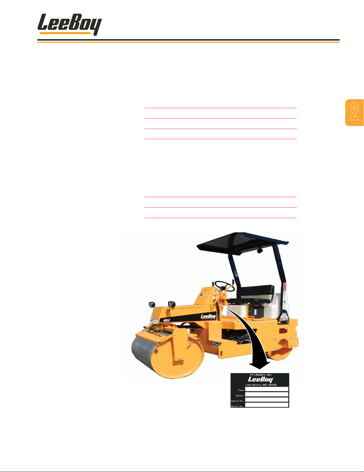
NAMEPLATE
The nameplate contains the specic model and serial
number used to identify the components for parts or
service information. Look in the engine owner’s manual
to nd the specic location of the engine nameplate for
your engine.
Figure 2-1. Nameplate Location
LeeBoy Model 400 & 400T Rollers 2-3
6 ft 6 in
4 ft 2 in
400
400
400T
400T
9 ft 2 in
400 / 400T
12 ft 8 in
9 ft 6 in
Information and Specications
SPECIFICATIONS CHARTS
LeeBoy authorized components. Section 7, IPL, for
The specications provided in this section are
applicable to the LeeBoy Model 400 and 400T Roller.
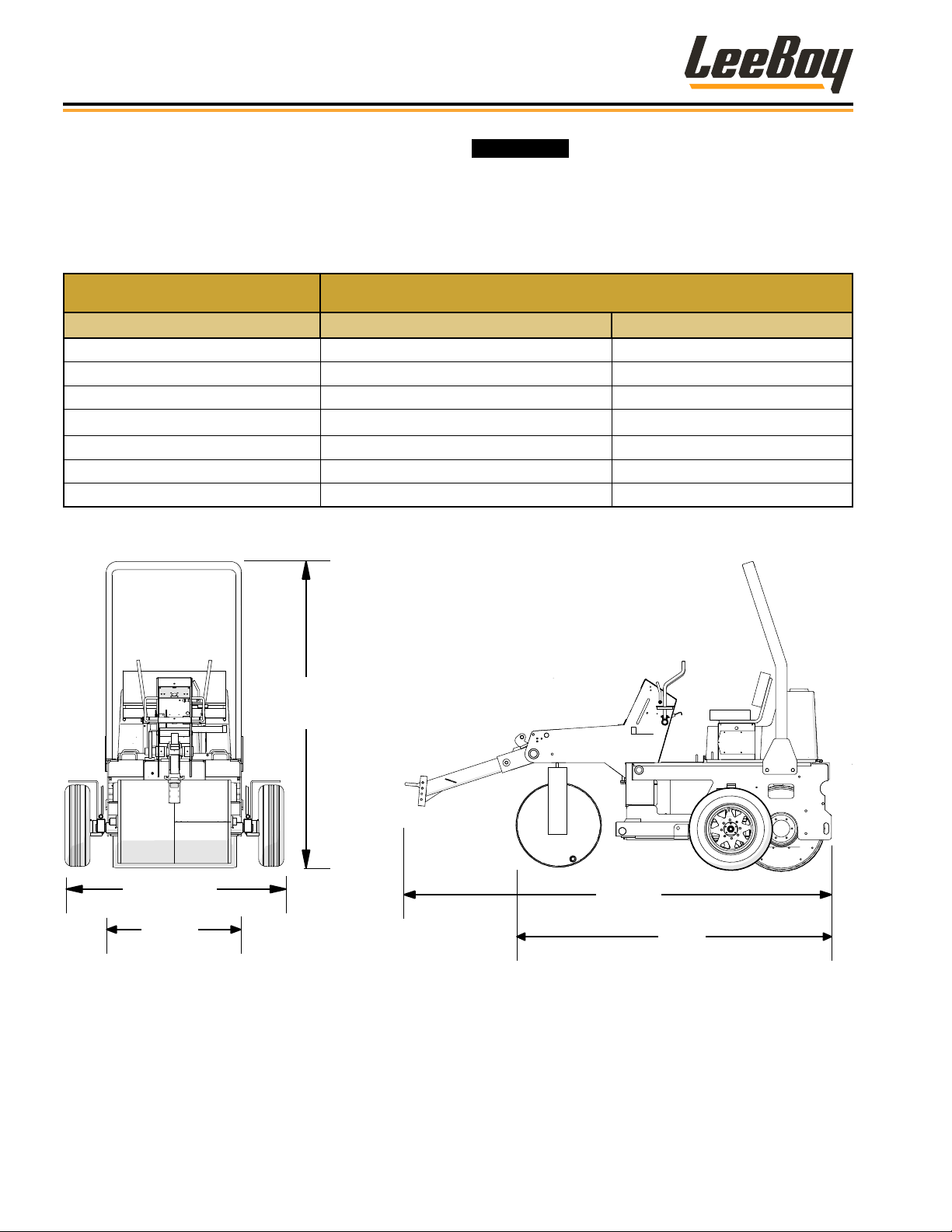
Table 2-1. Machine Dimensions
ITEM SPECIFICATION
Model 400 400T
Overall Length 9’ 6” (2.896 m) 12’ 8” (3.86 m)
Overall Height 9’ 2” (2.794 m) 9’ 2” (2.794 m)
Overall Width (Static/Loaded 4’ 2” (1.27 m) 6’ 6” (1.981 m)
Overall Weight 5640 lb (2558 kg) 6760 lbs. (3066 kg)
Wheelbase 6’6” (1.981 m) 6’6” (1.981 m)
Front Drum Width 40” (1016 mm) 40” (1016 mm)
Rear Drum Width 44” (1117.6 mm) 44” (1117.6 mm)
part numbers associated with the Model 400 and
Model 400T assemblies.
Replace original equipment only with
Figure 2-2. Machine Dimensions
LeeBoy Model 400 & 400T Rollers2-4
Information and Specications
Table 2-2. Engine Specications
ITEM SPECIFICATION
Model: Kubota V1505-E4B Tier 4
Horsepower
Displacement
Table 2-3. Electrical Specications
ITEM SPECIFICATION
Batteries 12 Vdc
Cold Cranking Amps (CCA) 835 CCA
System Voltage 12 Vdc
Table 2-4. Steering Specications
ITEM SPECIFICATION
Steering Hydraulic
Inside Turning Radius 14 ft 6 in (4.5 m)
24.8 HP @ 3000 RPM
(18.5 kW)
91.41 cubic inches
(1.498 L)
Table 2-6. Fuel and Lubricant Specications
ITEM SPECIFICATION
Engine Oil 15W-40
Hydraulic Oil 5W20 AWAT OIL
Coolant
Fuel Diesel
Grease
Table 2-7. Machine System Capacity Specications
ITEM SPECIFICATION
Fuel 8 gal (30.3 L)
Engine Lubrication Oil 1.59 gal (6.01 L)
Engine Coolant 1.28 gal (4.8 L)
Hydraulic Oil Reservoir 27 gal (102.20 L).
Water Tank 80 gal (302.83 L)
Table 2-8. Machine-Specic Specications
Ethylene/Glycol or Propylene
Glycol
Shell Avania EP Grease or
Equivalent
2
Table 2-5. Hydraulic Specications
ITEM SPECIFICATION
Function Pump 2100 psi (Relief)
Drive Motor 5800 psi (Relief)
Operating Pressure 5800 psi (Relief)
Hydraulic Filters Remote Pressure Filter
Oil Cooler
Ground Speed 0 - 5 mph (0 - 8 kph)
Radiator/Oil Cooler,
Engine Fan Cooling
ITEM SPECIFICATION
Calculated Maximum
Gradeability
Vibrator Vibrations Per
Minute (vpm)
Vibrator Centrifugal
Force
21.5%
2600 vpm
2814 lb (1276 kg)
LeeBoy Model 400 & 400T Rollers 2-5

Information and Specications
TORQUE SPECIFICATIONS
The following tables list torque values for standard
hardware. This is a guide for average application
involving typical stresses and machined surfaces.
Values are based upon physical limitations of clean,
plated and lubricated hardware. Under more extreme
conditions, individual torque value should be followed.
Conversion formulas are provided below:
Conversion Formula
ft-lb to N•m [ft-lb]*1.3558 = [N•m)
ft-lb to in-lb [ft-lb]*12 = [in-lb]
N•m to in-lb [N•m]*8.8508 = [in-lb]
Standard Inch Fasteners
Table 2-9. Torque Specications For Standard Inch Fasteners
CAPSCREWS: SAE GRADE 5 CAPSCREWS: SAE GRADE 8
SIZE THREAD
1/4 20 UNC 8 6 11 8 12 9 16 12
28 UNF 10 7 14 9 14 10 19 14
5/16 18 UNC 17 13 23 18 25 18 34 24
24 UNF 19 15 26 20 27 20 37 27
3/8 16 UNC 31 23 42 31 44 33 60 45
24 UNF 35 26 47 35 49 37 66 50
7/16 14 UNC 49 37 66 50 70 52 95 71
20 UNF 55 41 75 56 78 58 106 79
1/2 13 UNC 75 57 102 77 106 80 144 108
20 UNF 85 64 115 87 120 90 163 122
9/16 12 UNC 109 82 148 111 154 115 209 156
18 UNF 121 91 164 123 171 128 232 174
5/8 11 UNC 150 113 203 153 212 159 287 216
18 UNF 170 127 230 172 240 180 325 244
3/4 10 UNC 267 200 362 271 376 282 510 382
16 UNF 297 223 403 302 420 315 569 427
7/8 9 UNC 429 322 582 437 606 455 822 617
14 UNF 474 355 643 481 669 502 907 681
1 8 UNC 644 483 873 655 909 681 1232 923
14 UNF 722 542 979 735 1020 765 1383 1037
1-1/4 7 UNC 1121 840 1520 1139 1817 1363 2464 1848
12 UNF 1241 930 1683 1261 2012 1509 2728 2046
1-1/2 6 UNC 1950 1462 2644 1982 3162 2371 4287 3215
12 UNF 2194 1645 2975 2230 3557 2668 4823 3617
TORQUE (ft lb) TORQUE N•m TORQUE (ft lb) TORQUE N•m
Dry Lubed Dry Lubed Dry Lubed Dry Lubed
LeeBoy Model 400 & 400T Rollers2-6

Information and Specications
Metric Fasteners
Table 2-10. Torque Specications for Metric Fasteners
CLASS 8.8 [GRADE 5 EQUIVALENT] CLASS 10.9 [GRADE 8 EQUIVALENT]
NOMINAL SIZE
AND PITCH
M4 x 0.7 2 2 3 2 3 2 4 3
M5 x 0.8 5 3 7 4 7 5 9 7
M6 x 1 8 6 11 8 11 8 15 11
M8 x 1.25 19 14 26 19 27 20 37 27
M10 x 1.5 37 28 50 38 53 40 72 54
M12 x 1.75 65 49 88 66 93 70 126 95
M14 x 2 104 78 141 106 148 111 201 150
M16 x 2 161 121 218 164 230 173 312 235
M18 x 2.5 222 167 301 226 318 239 431 324
M20 x 2.5 314 236 426 320 449 337 609 457
M22 x 2.5 428 321 580 435 613 460 831 624
M24 x 3 543 407 736 552 777 582 1053 789
M27 x 3 796 597 1079 809 1139 854 1544 1158
M30 x 3.5 1079 809 1463 1097 1544 1158 2093 1570
TORQUE (ft lb) TORQUE N•m TORQUE (ft lb) TORQUE N•m
Dry Lubed Dry Lubed Dry Lubed Dry Lubed
2
Hydraulic Fittings
Tightening Flare-Type Tube Fittings
1. Check the are and are seat for defects that might
cause leakage.
2. Align tube with tting before tightening.
3. Lubricate connection.
4. Hand tighten swivel nut until snug.
5. To prevent twisting the tube(s), use two wrenches.
Place one wrench on the connector body and
tighten the swivel nut with the second to the torque
shown in Table 2-11.
NOTE: The torque values shown are based upon
lubricated connections.
Table 2-11. Torque Specications for Steel Flare
Type Tube Fittings
TUBE SIZE
OUTER
DIAMETER
(IN) (IN) (LB FT) (N•m)
3/16 7/16 8 11
1/4 9/16 12 16
5/16 5/8 16 22
3/8 11/16 23 31
1/2 7/8 38 52
5/8 1 54 73
3/4 1 1/4 75 102
7/8 1 3/8 83 113
NUT SIZE
ACROSS
FLATS
TORQUE VALUE
LeeBoy Model 400 & 400T Rollers 2-7
LA
L
E
LA
LH
Information and Specications
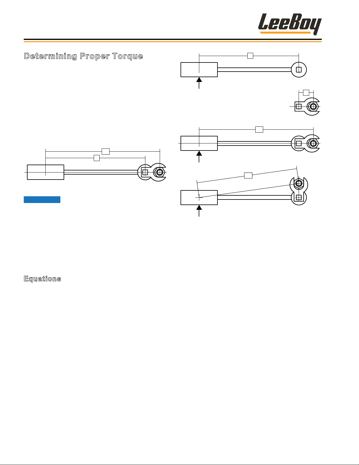
Determining Proper Torque
The only reliable method of creating a consistently
leak-free and long-lasting connection is to ensure the
coupling is brought to the proper torque. Using a torque
wrench with crowfoot is the best method, but the ats
method can be used if a torque wrench is not available.
The most straightforward method of determining the
correct torque setting is to multiply the desired torque
by the length of the wrench from the center of the handle
to the center of the drive (L); divided by the length of the
wrench from the center of the handle to the crowfoot
center (LA) as shown below:
L
Figure 2-3. Torque Wrench - Crowfoot
The minimum torque values are
adequate for sealing most applications. Maximum
torque values should never be exceeded.
There are several methods of determining the correct
setting on the torque wrench when using a crowfoot. All
of the methods involve making the setting proportional
to the effective change in length of the wrench multiplied
by the desired nal torque. The equations and
illustration below describe proper measurements. (Use
LEGEND under Figure 2-4)
Equations
• Torque setting if the crowfoot is placed in line with
respect to the wrench:
TS = TD * L / LA
OR
TS = TD * L / (L+E)
• Torque setting if the crowfoot is placed at 90° with
respect to the wrench
TS = TD * L / LH
OR
Figure 2-4. Measurements Needed
LEGEND
L = Distance from center of torque wrench handle to the
center of socket drive
E = Distance from center of socket drive to the center of
crowfoot
LA = Distance from center of torque wrench handle to
the center of crowfoot
LH = Distance from center of torque wrench handle to
the center of crowfoot, when mounted at 90°
TD = Desired torque at the tting
TS = Torque setting indicated on wrench
TS = TD * L / √(L2 + E2)
• To estimate the crowfoot size (E)
E = Drive Size * 0.5 + Distance between Drive and
Open End + Wrench Size * 0.5774
LeeBoy Model 400 & 400T Rollers2-8
 Loading...