

Page 1

Operations, Service, and Parts Manual
3000C Force Feed Loader
Manual No. 1015203-01
This manual applies to
Serial Number 131024
and above.
Page 2

3000C Force Feed Loaderii
Page 3

Thumb Index
Safety
Information and Specifications
Component Location
Operation
Maintenance
1
2
3
4
5
Schematics
Illustrated Parts List (IPL)
6
7
Page 4

DISCLAIMER AND COPYRIGHT
Disclaimer:
All information, illustrations and specications in this manual are based on the latest information available at the time
of publishing. The illustrations used in this manual are intended as representative reference views only. Moreover,
because of our continuous product improvement policy, we may modify information, illustrations and/or specications
to explain and/or exemplify a product, service or maintenance improvement. We reserve the right to make any
change at any time without notice. VT LeeBoy, Inc., VT LeeBoy, LeeBoy, and Rosco are all the same entity and are
used interchangeably.
©2016 VT LeeBoy, Inc.
LeeBoy reserves all copyright and other rights in this manual and the manual’s content. No part of this manual may
be reproduced or used in any way without the written permission of LeeBoy, except as necessary to operate LeeBoy
equipment.
California Proposition 65 WARNING
Diesel engine exhaust and some of its constituents are known to the State of California to cause cancer, birth
defects, and other reproductive harm.
Battery posts, terminals and other related accessories contain lead and lead compounds, chemicals known to the
State of California to cause cancer and other reproductive harm. Wash hands after handling.
iv
Page 5

TABLE OF CONTENTS
Page
Safety . . . . . . . . . . . . . . . . . . . . . . . . . . . . . . . . . . . . 1-1
Introduction . . . . . . . . . . . . . . . . . . . . . . . . . . . . . . . . 1-3
Safety Precautions . . . . . . . . . . . . . . . . . . . . . . . . . . . . . 1-4
Safety Labels . . . . . . . . . . . . . . . . . . . . . . . . . . . . . . . 1-8
Machine Specic Precautions . . . . . . . . . . . . . . . . . . . . . . . 1-10
Operating Precautions . . . . . . . . . . . . . . . . . . . . . . . . . . . 1-12
Maintenance Precautions . . . . . . . . . . . . . . . . . . . . . . . . . 1-12
Information and Specications . . . . . . . . . . . . . . . . . . . . . . . . 2-1
Limited Warranty Policy . . . . . . . . . . . . . . . . . . . . . . . . . . 2-2
General Information and Specications . . . . . . . . . . . . . . . . . . . 2-4
Torque Specications . . . . . . . . . . . . . . . . . . . . . . . . . . . 2-7
Component Location . . . . . . . . . . . . . . . . . . . . . . . . . . . . . 3-1
Control Consoles . . . . . . . . . . . . . . . . . . . . . . . . . . . . . 3-3
Operation . . . . . . . . . . . . . . . . . . . . . . . . . . . . . . . . . . 4-1
General Information . . . . . . . . . . . . . . . . . . . . . . . . . . . . 4-3
Operating Safety . . . . . . . . . . . . . . . . . . . . . . . . . . . . . . 4-3
Pre-Start Inspection . . . . . . . . . . . . . . . . . . . . . . . . . . . . 4-5
Machine Adjustments . . . . . . . . . . . . . . . . . . . . . . . . . . . 4-6
Operating Procedures . . . . . . . . . . . . . . . . . . . . . . . . . . . 4-8
Loading Material . . . . . . . . . . . . . . . . . . . . . . . . . . . . . . 4-14
Transporting . . . . . . . . . . . . . . . . . . . . . . . . . . . . . . . . 4-14
Towing . . . . . . . . . . . . . . . . . . . . . . . . . . . . . . . . . . 4-15
Maintenance . . . . . . . . . . . . . . . . . . . . . . . . . . . . . . . . . 5-1
General Information . . . . . . . . . . . . . . . . . . . . . . . . . . . . 5-3
Maintenance Schedule . . . . . . . . . . . . . . . . . . . . . . . . . . . 5-4
Lubrication Points . . . . . . . . . . . . . . . . . . . . . . . . . . . . . 5-6
Tire Replacement . . . . . . . . . . . . . . . . . . . . . . . . . . . . . 5-7
v
Page 6

Cooling System . . . . . . . . . . . . . . . . . . . . . . . . . . . . . . 5-7
Engine Maintenance . . . . . . . . . . . . . . . . . . . . . . . . . . . . 5-8
Fuel System . . . . . . . . . . . . . . . . . . . . . . . . . . . . . . . . 5-13
Hydraulic System . . . . . . . . . . . . . . . . . . . . . . . . . . . . . 5-14
Electrical System . . . . . . . . . . . . . . . . . . . . . . . . . . . . . . 5-17
Replacing Components . . . . . . . . . . . . . . . . . . . . . . . . . . 5-19
Weldment . . . . . . . . . . . . . . . . . . . . . . . . . . . . . . . . . 5-23
Troubleshooting Chart . . . . . . . . . . . . . . . . . . . . . . . . . . . 5-24
Schematics . . . . . . . . . . . . . . . . . . . . . . . . . . . . . . . . . 6-1
Group, Relays, Grid Heater . . . . . . . . . . . . . . . . . . . . . . . . . 6-3
Panel, Instrument, Top Right (1 of 2) . . . . . . . . . . . . . . . . . . . . . 6-5
Panel, Instrument, Top Right (2 of 2) . . . . . . . . . . . . . . . . . . . . 6-7
Panel, Instrument, Lower Right . . . . . . . . . . . . . . . . . . . . . . . 6-9
Harness, Main (1 of 2) . . . . . . . . . . . . . . . . . . . . . . . . . . . . 6-11
Harness, Main (2 of 2) . . . . . . . . . . . . . . . . . . . . . . . . . . . 6-13
Harness, Engine (1 of 2) . . . . . . . . . . . . . . . . . . . . . . . . . . 6-15
Harness, Engine (2 of 2) . . . . . . . . . . . . . . . . . . . . . . . . . . 6-17
Schematic, Electrical (1 of 2) . . . . . . . . . . . . . . . . . . . . . . . . 6-19
Schematic, Electrical (2 of 2) . . . . . . . . . . . . . . . . . . . . . . . . 6-21
Harness, Emission Sensor . . . . . . . . . . . . . . . . . . . . . . . . . 6-23
Hydraulic Schematic (1 of 2) . . . . . . . . . . . . . . . . . . . . . . . . 6-25
Hydraulic Schematic (2 of 2) . . . . . . . . . . . . . . . . . . . . . . . . 6-27
Hydraulic Hose Schematic (1 of 3) . . . . . . . . . . . . . . . . . . . . . 6-29
Hydraulic Hose Schematic (2 of 3) . . . . . . . . . . . . . . . . . . . . . 6-31
Hydraulic Hose Schematic (3 of 3) . . . . . . . . . . . . . . . . . . . . . 6-33
Illustrated Parts List . . . . . . . . . . . . . . . . . . . . . . . . . . . . . 7-1
Quick Reference . . . . . . . . . . . . . . . . . . . . . . . . . . . . . 7-3
Loader Frame Assembly . . . . . . . . . . . . . . . . . . . . . . . . . . 7-4
3000 Force Feeder Loader Auger Moldboard . . . . . . . . . . . . . . . 7-6
3000 Force Feed Loader Tapered Moldboard (1 of 2) . . . . . . . . . . . 7-8
3000 Force Feed Loader Tapered Moldboard (2 of 2) . . . . . . . . . . . 7-10
FFLA Feeder Assembly - Auger (1 of 3) . . . . . . . . . . . . . . . . . . . 7-12
FFLA Feeder Assembly - Auger (2 of 3) . . . . . . . . . . . . . . . . . . 7-14
FFLA Feeder Assembly - Auger (3 of 3) . . . . . . . . . . . . . . . . . . 7-16
FFLT Feeder Assembly - Tapered (1 of 3) . . . . . . . . . . . . . . . . . . 7-18
vi 3000C Force Feed Loader
Page 7

Feeder Assembly - Tapered (2 of 3) . . . . . . . . . . . . . . . . . . . . 7-20
Feeder Assembly - Tapered (3 of 3) . . . . . . . . . . . . . . . . . . . . 7-22
Front Axle Assembly . . . . . . . . . . . . . . . . . . . . . . . . . . . . 7-24
Rear End Assembly . . . . . . . . . . . . . . . . . . . . . . . . . . . . 7-26
Gear Box (1 of 2) . . . . . . . . . . . . . . . . . . . . . . . . . . . . . . 7-28
Gear Box (2 of 2) . . . . . . . . . . . . . . . . . . . . . . . . . . . . . . 7-30
Hub Reduction . . . . . . . . . . . . . . . . . . . . . . . . . . . . . . . 7-32
Central Housing . . . . . . . . . . . . . . . . . . . . . . . . . . . . . . 7-34
Brakes . . . . . . . . . . . . . . . . . . . . . . . . . . . . . . . . . . . 7-36
Differential . . . . . . . . . . . . . . . . . . . . . . . . . . . . . . . . . 7-38
Hydraulic Tank Group . . . . . . . . . . . . . . . . . . . . . . . . . . . 7-40
Fuel Tank Group . . . . . . . . . . . . . . . . . . . . . . . . . . . . . 7-42
Conveyor Assembly . . . . . . . . . . . . . . . . . . . . . . . . . . . . 7-44
Tail Pulley Group . . . . . . . . . . . . . . . . . . . . . . . . . . . . . . 7-46
Head Pulley Assembly . . . . . . . . . . . . . . . . . . . . . . . . . . . 7-48
Cab Group . . . . . . . . . . . . . . . . . . . . . . . . . . . . . . . . . 7-50
Cab Mirrors and Lights . . . . . . . . . . . . . . . . . . . . . . . . . . . 7-52
Cab (with Glass) . . . . . . . . . . . . . . . . . . . . . . . . . . . . . . 7-54
Cab Door . . . . . . . . . . . . . . . . . . . . . . . . . . . . . . . . . 7-56
Steering Wheel and Components . . . . . . . . . . . . . . . . . . . . . 7-58
Instrument Panel Controls . . . . . . . . . . . . . . . . . . . . . . . . . 7-60
Relay Group . . . . . . . . . . . . . . . . . . . . . . . . . . . . . . . . 7-62
Engine and Pumps . . . . . . . . . . . . . . . . . . . . . . . . . . . . . 7-64
Engine, T4F . . . . . . . . . . . . . . . . . . . . . . . . . . . . . . . . 7-66
Mufer and Air Cleaner Arrangement . . . . . . . . . . . . . . . . . . . . 7-68
Radiator and Battery Arrangement . . . . . . . . . . . . . . . . . . . . . 7-70
Hydraulic Group . . . . . . . . . . . . . . . . . . . . . . . . . . . . . . 7-72
Mechanical Enclosures . . . . . . . . . . . . . . . . . . . . . . . . . . 7-74
Engine Cover Assembly . . . . . . . . . . . . . . . . . . . . . . . . . . 7-76
Direction Light Assembly . . . . . . . . . . . . . . . . . . . . . . . . . . 7-78
Air Conditioning/Heat Option . . . . . . . . . . . . . . . . . . . . . . . . 7-80
Radio Option . . . . . . . . . . . . . . . . . . . . . . . . . . . . . . . . 7-82
Swivel Conveyor Option . . . . . . . . . . . . . . . . . . . . . . . . . . 7-84
Swivel Conveyor - Hydraulics Option (1 of 2) . . . . . . . . . . . . . . . . 7-86
3000C Force Feed Loader vii
Page 8

Swivel Conveyor - Hydraulics Option (2 of 2) . . . . . . . . . . . . . . . . 7-88
Swivel Conveyor Assembly (1 of 2) . . . . . . . . . . . . . . . . . . . . . 7-90
Swivel Conveyor Assembly (2 of 2) . . . . . . . . . . . . . . . . . . . . . 7-92
Swivel Stand Option . . . . . . . . . . . . . . . . . . . . . . . . . . . . 7-94
Alphabetical Parts Index . . . . . . . . . . . . . . . . . . . . . . . . . . 7-96
viii 3000C Force Feed Loader
Page 9

Section 1
SAFETY
Page
Section 1 . . . . . . . . . . . . . . . . . . . . . . . . . . . . . . . . . . . 1-1
Introduction . . . . . . . . . . . . . . . . . . . . . . . . . . . . . . . . 1-3
Safety Precautions . . . . . . . . . . . . . . . . . . . . . . . . . . . . . 1-4
Safety Labels . . . . . . . . . . . . . . . . . . . . . . . . . . . . . . . 1-8
Location . . . . . . . . . . . . . . . . . . . . . . . . . . . . . . . 1-8
Safety Decals Care . . . . . . . . . . . . . . . . . . . . . . . . . 1-9
Decal Installation (Sticker Type) . . . . . . . . . . . . . . . . . . . 1-9
Decal Installation (Top Protected) . . . . . . . . . . . . . . . . . . 1-9
Machine Specic Precautions . . . . . . . . . . . . . . . . . . . . . . . 1-10
Hot Material Precautions . . . . . . . . . . . . . . . . . . . . . . . 1-10
Hydraulic Systems Precautions . . . . . . . . . . . . . . . . . . . 1-10
Refueling Precautions . . . . . . . . . . . . . . . . . . . . . . . . 1-10
Operating Precautions . . . . . . . . . . . . . . . . . . . . . . . . . . . 1-12
Storage Precautions . . . . . . . . . . . . . . . . . . . . . . . . . . . . 1-12
Maintenance Precautions . . . . . . . . . . . . . . . . . . . . . . . . . 1-12
3000C Force Feed Loader
Battery Precautions . . . . . . . . . . . . . . . . . . . . . . . . . 1-10
Tire Precautions . . . . . . . . . . . . . . . . . . . . . . . . . . . 1-11
Starting and Stopping Precautions . . . . . . . . . . . . . . . . . . 1-12
Parking Precautions . . . . . . . . . . . . . . . . . . . . . . . . . 1-12
1-1
Page 10

NOTES
3000C Force Feed Loader1-2
Page 11

INTRODUCTION
This manual provides important information to familiarize
you with safe operating and maintenance procedures.
Even though you may be familiar with similar equipment,
you MUST read and understand this manual before
operating the 3000C Force Feed Loader and follow its
instructions when operating the loader.
Safety is everyone’s business and our top concern.
Knowing the guidelines covered in this section will help
ensure your safety, the safety of those around you, and
proper loader operation.
Keep safety labels in good condition. If safety labels
become missing or damaged, replace them with
new matching labels. Replacement safety labels are
available from your LeeBoy dealer (see Contact
Information on Page 2-3 and Safety Labels onPage
1-8).
Indicates a hazardous situation which, if
not avoided, will result in death or serious injury.
1
Indicates a hazardous situation which, if
not avoided, could result in death or serious injury.
Indicates a hazardous situation which, if
not avoided, could result in minor or moderate injury.
Indicates a situation which can cause
damage to the equipment, personal property and/or the
environment, or cause the LeeBoy 3000B Force Feed
Loader to operate improperly.
NOTE: Indicates a procedure, practice or condition
that should be followed in order for the
force feed loader or component to function
in the manner intended.
3000C Force Feed Loader 1-3
Page 12

SAFETY PRECAUTIONS
The safety messages that follow have CAUTION level
hazards.
Pre-Operation Hazard
Read and understand this Operation Manual
before operating or servicing the machine
to ensure that safe operating practices and
maintenance procedures are followed.
• Never permit anyone to service or operate the LB
Performance machine without proper training.
• Safety signs and labels are additional reminders for
safe operating and maintenance techniques.
• Contact LB Performance or an authorized LB
Performance dealer for additional training.
• Make sure you are aware of all laws and regulations
that are in effect for the location in which the force
feed loader is operated.
• Make sure you have all necessary licenses to operate
the force feed loader.
Suffocation Hazard
Carbon monoxide poisoning is a serious
condition that occurs as a result of improper
ventilation.
• Never operate the internal combustion engine on this
machine in an enclosed area with poor ventilation.
Ensure proper ventillation to reduce risk of carbon
monoxide poisoning or death.
Exhaust Hazard
All internal combustion engines create
carbon monoxide gas during operation and
special precautions are required to avoid
carbon monoxide poisoning:
• Never block windows, vents or other means of
ventilation.
• Always ensure that all connections are tightened to
specications after repair is made to the exhaust
system.
The safety messages that follow have WARNING
level hazards.
The safety messages that follow have DANGER level
hazards.
Electrocution Hazard
If your machine comes in contact with
electric power lines, observe the following:
• Stay in the operators seat.
• Warn other workers to stay away and do not touch any
control or any part of the machine.
• If contact can be broken, drive the machine away from
the danger zone.
• If contact cannot be broken, stay in the operators seat
until told that power is off.
• Failure to observe these directions could result in
electrocution or death.
Crush Hazard
Keep bystanders away from work area before and
during operation.
Modification Hazard
Never modify the LB Performance machine without the
written consent of LB Performance. Any modication
can affect the safe operation of the force feed loader
and may cause personal injury or death.
Exposure Hazard
Operators of the motor force feed loader
must be aware of their work environment
and the equipment needed to work safely.
3000C Force Feed Loader1-4
Page 13

• Always wear personal protective equipment, including
appropriate clothing, gloves, work shoes, and
protection for eyes and ears, as required by the task
at hand.
Explosion Hazard
While the engine is running or the battery is
charging, hydrogen gas is being produced
and can be easily ignited. Keep the area
around the battery well-ventilated and keep
sparks, open ame, and any other form of
ignition out of the area.
• Always disconnect the negative (-) battery cable
before servicing the force feed loader.
• DO NOT start the engine by shorting the starter circuit
or any other starting method not stated in this manual.
Only use the starting procedure as described in this
manual to start the engine.
• Never charge a frozen battery. Always slowly warm the
battery to room temperature before charging.
Fire and Explosion Hazard
• Diesel fuel is ammable and explosive under certain
conditions.
• Never use a shop rag to catch fuel.
• Wipe up all spills immediately.
• Never refuel with the engine running.
• Store any containers containing fuel in a well-
ventilated area, away from any combustibles or
sources of ignition.
Fire Hazard
Have appropriate safety equipment
available. Have all re extinguishers
checked periodically for proper operation
and/or readiness.
• Keep a charged re extinguisher within reach when
working in an environment where a re may occur.
• Always read and follow safety-related precautions
found on containers of hazardous substances
like parts cleaners, primers, sealants and sealant
removers.
Entanglement/Sever Hazard
Verify there are no people, obstacles or
other equipment near the machine before
starting the engine. Sound the horn as a
warning before starting the engine.
If the engine must be serviced while it is
operating, Remove all jewelry and tie back
long hair before operating or servicing the
machine.
• Keep hands, other body parts, and clothing away
from moving/rotating parts.
• Always stop the engine before beginning service.
Before maintenance, remove negative battery cable
from battery post to ensure vehicle is not operated
during maintenance.
• Verify that all guards and covers are properly attached
before starting the engine. Do not start the engine if
any guards or covers are not properly installed on the
force feed loader.
• If you must run the engine during maintenance
procedures, make sure you have a helper to keep
bystanders clear of the force feed loader and make
observations of moving parts as requested by the
operator.
• Always turn the start switch to the OFF position after
operation is complete and remove the key from the
switch. Keep the key in your possession when the
force feed loader is not operating.
• Attach a “Do Not Operate” tag near the key switch
while performing maintenance on the equipment.
• Never operate the engine while wearing a headset to
listen to a radio or music because it will be difcult to
hear the warning signals.
• Always start the engine and operate the controls while
seated in the operators seat.
Alcohol and Drug Hazard
Never operate the machine while under the
inuence of alcohol, drugs, or when ill.
1
3000C Force Feed Loader 1-5
Page 14

Piercing Hazard
High-pressure hydraulic uid or fuel can
penetrate your skin and result in serious
injury. Avoid skin contact with high-pressure
hydraulic uid or diesel fuel spray caused by
a hydraulic or fuel system leak such as a
broken hydraulic hose or fuel injection line.
• If you are exposed to high-pressure hydraulic uid or
fuel spray, obtain prompt medical treatment.
• Never check for a hydraulic uid or fuel leak with your
hands. Always use a piece of wood or cardboard.
Contact your authorized LeeBoy dealer or distributor
to repair the damaged parts.
Flying Object Hazard
Always wear eye protection when cleaning
the LeeBoy 3000B Force Feed Loader with
compressed air or high-pressure water.
The safety messages that follow have CAUTION level
hazards.
Poor Lighting Hazard
The work area must be well lit to ensure safe and proper
operation.
• Ensure that the work area is adequately illuminated.
• Always install wire cages on portable safety lights.
Tool Hazard
Always use tools appropriate for the task at hand and
use the correct size tool for loosening or tightening LB
Performance machine parts.
Dust, ying debris, compressed air, pressurized water or
steam may cause eye injury.
Coolant Hazard
Coolant must be handled properly to ensure
operator safety.
• Wear eye protection and rubber gloves when handling
engine coolant.
• If contact with the eyes occurs, ush eyes with clean
water for 15 minutes.
• If contact with skin occurs, wash immediately with
soap and clean water.
Burn Hazard
Some of the machine’s surfaces become
very hot during operation and shortly after
shutdown.
• Keep hands and other body parts away from hot
machine surfaces.
• Handle hot components with heat-resistant gloves.
3000C Force Feed Loader1-6
Page 15

The safety messages that follow have NOTICE level
hazards.
• Any part found defective or incorrect during inspection
must be replaced.
• Always tighten components to the specied torque.
Loose parts can cause damage or improper operation
• Only use replacement parts approved by LB
Performance. Other replacement parts may affect
warranty coverage.
Follow the EPA and other governmental
agency guidelines for the proper
disposal of hazardous materials such
as engine oil, diesel fuel, and engine
coolant. Consult your local authorities
or reclamation facility for guidelines.
• Dispose of hazardous materials in accordance with
all applicable laws and regulations. Never dispose of
hazardous materials by dumping them into a sewer, on
the ground, or into groundwater or waterways.
1
• Clean all accumulated dirt and debris on the body
and components before inspecting or performing
preventive maintenance procedures and repairs.
Operating a force feed loader with accumulated dirt
and debris will cause premature wear of components.
Accumulated dirt and debris also hinders effective
force feed loader inspection.
• Retrieve any tools or parts that may have dropped
inside of the force feed loader to avoid improper force
feed loader operation.
• If any alert indicator illuminates during operation, stop
the engine immediately. Determine the cause and
repair the problem before continuing to operate the
force feed loader.
3000C Force Feed Loader 1-7
Page 16

(Swivel option only)
(Both sides)
(Both sides)
CHANGE FILTER:
Hydraulic Return: 500 hours
Hydraulic Suction: 500 hours
856599
CAUTION
856601
CAUTION
HYDRAULIC
OIL ONLY!
Keep clean
856605
KEEP DOOR CLOSED WHEN IN OPERATION!
Failure to comply could result in death or serious
injury.
WARNING
(Fuel Cap)
SAFETY LABELS
Location
If a LeeBoy machine has been repainted, it is extremely
important that all decals referring to CAUTION,
WARNING and DANGER be replaced in their proper
locations. The illustration on this page will aid you in
determining the proper locations. A description is
provided below for each safety label.
For additional instructions, contact your dealer.
NOTE: It is the responsibility of the owner and
operator to make sure that all safety labels
are readable and located on the machine as
designated by LeeBoy.
Figure 4-1. Safety Label Locations
3000C Force Feed Loader1-8
Page 17

Safety Decals Care
• Keep safety decals and signs clean and legible at all
times.
• Become familiar with the content and position of each
safety decal. Decals include important information.
• Replace decals and signs that are missing or become
impossible to read.
• When replacing parts that display a safety decal,
ensure that the new part is tted with a decal as well.
• Obtain safety decals or signs from your authorized
LeeBoy dealer.
Decal Installation (Sticker Type)
1. Be sure that the installation area is clean and dry.
Use hot, soapy water to clean the surface where the
decal will be applied. Thoroughly dry the surface.
2. Measure and test tting before removing the decal
paper backing to position.
3. Align the decal over the specied area and carefully
press exposed portion into place.
Decal Installation (Top Protected)
1. If the decal has a protective top paper, use hot
soapy water on the surface where the decal will be
applied. Leave wet.
2. After determining the correct decal location, remove
the protective back paper and soak decal in clean,
soapy water before application. This will help to
alleviate air bubbles in the applied decal.
3. Smooth the decal into place with a squeegee and
check for air bubbles.
4. Small air pockets can be pierced with a pin and
smoothed using a piece of the decal backing.
5. When the decal is completely smooth, carefully
remove the top paper.
1
4. Slowly remove the remaining backing and carefully
smooth the remaining portion of the decal into place.
5. Small air pockets can be pierced with a pin and
smoothed using a piece of the decal backing.
3000C Force Feed Loader 1-9
Page 18

MACHINE SPECIFIC PRECAUTIONS
Hot Material Precautions
• Wear protective gear for face, hands, feet, and body
when operating the loader.
• Allow machine to cool before repairing or maintaining
working components.
• DO NOT remove radiator cap, drain plugs, service
grease ttings or pressure taps while engine is hot.
Add coolant to the radiator and perform other services
only when the engine is stopped and fully cooled.
Hydraulic Systems Precautions
• Ensure all components are in good working condition.
Replace any worn, cut, abraded, attened or crimped
hoses and metal lines.
• DO NOT attempt makeshift repairs using tape, clamps
or cements. The hydraulic system operates under
extremely high pressure and such repairs could
cause serious injury.
Refueling Precautions
• When refueling, keep the hose nozzle or funnel in
contact with the metal on the fuel tank to avoid the
possibility of an electrical spark lighting the fuel.
Maintain control of ller nozzle.
DO NOT overll the fuel tank as
overow creates a re hazard when spilled on hot
components.
DO NOT smoke when refueling.
NEVER refuel when the engine is running. Fuel is
highly ammable and should be handled with care.
Death or serious injury can occur due to explosion
and/or re.
• DO NOT ll tank to capacity. Allow room for expansion
to reduce the risk of fuel expanding and spilling from
the tank.
• Tighten fuel cap securely. Should fuel cap be lost,
replace it with an original manufacturer’s approved
cap. Pressurization of the tank may result from using
an incorrect fuel cap.
• Prevent res by keeping the machine clean of
accumulated debris, grease and spilled fuel.
• Use ultra-low sulfur diesel fuel (ULSD) only.
• Wear proper hand and eye protection when checking
for a high pressure leak.
Hydraulic oil under pressure can
cause serious personal injury. Check for oil leaks
with a piece of cardboard. Do not expose hands to
possible high-pressure oil. Turn off engine before
attempting to tighten oil lines and ttings.
• Escaping pressurized hydraulic uid has force
sufcient to penetrate the skin and cause serious
personal injury. Ensure pressure is relieved before
disconnecting lines, hoses or valves.
• If injury from concentrated high pressure steam
or hydraulic uid occurs, seek medical attention
immediately. Injuries resulting from hydraulic uid
penetrating the skin’s surface can result in serious
infections or toxic reactions.
Battery Precautions
• Keep all sparks and ames away from batteries, as
gas given off by electrolytes is explosive.
• Acid propelled by an explosion can cause blindness
if it comes in contact with eyes. Always wear safety
glasses when working near batteries.
• If you come into contact with battery electrolyte
solution, wash off immediately. Chemicals can cause
burns.
• Always disconnect the battery ground cable before
working on the electrical system to avoid injury from
spark or short circuit.
• To avoid electrolyte loss, DO NOT tip batteries more
than 45 degrees.
• Use jumper cables ONLY in recommended manner.
Improper use can result in battery explosion or
unexpected machine motion.
3000C Force Feed Loader1-10
Page 19

Tire Precautions
DO NOT mount or demount tires
without proper training. A violent explosion can
occur.
Follow all procedures and safety instructions. Wall
charts containing mounting and demounting instructions
for all rims are available through the United States
Department of Transportation (DOT), Washington, D.C.
When in doubt, contact a qualied
tire dealer or repair service to perform required tire
maintenance.
Inspection
• Clean rims and repaint to stop detrimental effects of
corrosion and facilitate checking and tire mounting.
• Be very careful to clean all dirt and rust from rims.
This is important for securing rims into the proper
position.
• Check rim components periodically for cracks.
Replace all cracked, badly worn, severely rusted, and
otherwise damaged components with new parts of the
same size and type. If you are not sure about proper
mating of tire and wheel parts, consult a wheel and rim
expert.
DO NOT attempt to rework, weld,
heat or braze any rim components that are cracked,
broken or damaged. Replace damaged components
with new parts of the same size and type. Mixing
parts of one type with those of another is potentially
dangerous.
DO NOT reinate a at tire without
rst inspecting the tire, tube, ap, rim, and wheel
assembly for damage. Be sure parts are secured
before ination.
Starting and Stopping
Precautions
• Check all around loader to make sure there are no
people working on the machine or in the path of the
machine before starting. DO NOT start until area is
clear. Death or serious injury can occur to bystanders
from being crushed under a moving machine.
Check brakes, steering and other
control devices in accordance with instructions
before starting. Be sure parking brake is applied and
the direction control lever is in neutral.
• Latch seat belt (if equipped) and adjust to t snugly.
• Only start and operate the machine from the
operator’s seat. DO NOT bypass the neutral-start
system. If the system malfunctions, it must be
repaired.
DO NOT operate the engine in an
enclosed area without proper ventillation. Exhaust
gasses are odorless and deadly.
Parking Precautions
• Park the machine on level ground whenever possible.
On grades, park with wheels securely blocked.
Always apply parking brake.
• Before leaving operator’s station:
1. Place Forward/Reverse lever in neutral.
2. Turn off all accessories.
3. Set parking brake.
4. Shut off engine.
• Always remove ignition key when leaving the loader
parked or unattended.
1
3000C Force Feed Loader 1-11
Page 20

OPERATING PRECAUTIONS
• Always comply with local regulations regarding
moving equipment on public roads and highways.
• Know and use the hand signals required for a
particular job. Know who has the responsibility for
signaling.
• Make sure all lights and reectors comply with state
and local regulations. Keep them clean and in good
working order so they can be seen clearly by all trafc.
DO NOT stand between the equipment
and the truck while the truck is being coupled
with the force feed loader. Death or serious injury
can result from being crushed between the two
machines. DO NOT ride on attachments.
Some work situations require
more attention to stopping distances, particularly
when going downhill. The larger the force feed
loader, the more it will slide on a slippery surface.
Steeper grades require longer stopping distances.
Familiarize yourself with these variables so you
can anticipate when longer stopping distances are
required.
• Check all gauges and warning instruments for proper
operation. If malfunctions are found, shut down the
machine and report the problem. If the failure causes
loss of steering control, loss of brake control or loss
of engine power, stop machine motion as quickly as
possible. Apply parking brake and keep the machine
securely parked until the failure is corrected or the
machine can be safely towed.
• DO NOT operate unit when warning buzzer/light is
illuminated.
• Drive the machine with care. Make sure speed is
compatible with conditions. Use caution on rough
ground, slopes and while turning.
• Be alert for hazards and obstructions such as ditches,
trees, cliffs, overhead power lines, and areas where
there is danger of a slide.
• Be aware and understand the job site trafc ow
patterns.
• Obey agmen, road signs and signals.
• Watch for bystanders. Never allow anyone to be
under the machine during operation. Never allow
anyone to reach into the machine during use.
• Operator must know how to use signaling devices
when roading the machine. Operator must also
understand which circumstances require use of each
signal. Use tail lights, slow moving vehicle signs, and
warning beacon as needed when traveling on public
roads.
• When required, provide an escort for roading.
• DO NOT tow the machine, except to remove from road
or to load on trailer.
MAINTENANCE PRECAUTIONS
• DO NOT attempt repairs unless trained to do so.
Refer to manuals and experienced repair personnel
for help.
• Before conducting maintenance, securely block the
machine and any components that may fall. Block
any working components to prevent unexpected
movement while repairs are being made.
• Always wear safety glasses and other required safety
equipment when servicing or making repairs.
• Disconnect battery before working on the electrical
system.
• Avoid lubrication or mechanical adjustments while the
machine is in motion or while engine is operating. If
lubrication or mechanical adjustment is necessary:
1. Place Forward/Reverse control in neutral.
2. Apply parking brake.
3. Shut off engine.
4. Place equipment in a safe position.
5. Securely block wheels.
6. Use extreme caution.
• Never make repairs on pressurized components such
as uid lines, the gas system or mechanical items until
the pressure has been relieved.
• Keep brake and steering systems in good operating
condition.
3000C Force Feed Loader1-12
Page 21

Section 2
INFORMATION AND SPECIFICATIONS
Page
Section 2 . . . . . . . . . . . . . . . . . . . . . . . . . . . . . . . . . . 2-1
Limited Warranty Policy . . . . . . . . . . . . . . . . . . . . . . . . . . 2-2
General Information and Specications . . . . . . . . . . . . . . . . . . . 2-4
Torque Specications . . . . . . . . . . . . . . . . . . . . . . . . . . . 2-7
Standard Inch Fasteners . . . . . . . . . . . . . . . . . . . . . . . 2-7
Metric Fasteners . . . . . . . . . . . . . . . . . . . . . . . . . . . 2-8
Hydraulic Fittings . . . . . . . . . . . . . . . . . . . . . . . . . . 2-8
Determining Proper Torque . . . . . . . . . . . . . . . . . . . . . 2-9
3000C Force Feed Loader
2-1
Page 22

Information and Specications
LIMITED WARRANTY POLICY
Warranty
Subject to the limitations, exclusions, and claims procedures set
forth herein, VT LeeBoy, Inc. warrants [to the rst retail purchaser]
that this product will be free from substantial defects in materials and
workmanship during the warranty period.
If a defect in material or workmanship is found, your authorized
LeeBoy Dealer is to be notied during the warranty period. LeeBoy
and its authorized Dealer will repair or replace any part or component
of the unit or part that fails to conform to the warranty during the
warranty period.
The warranty period will begin on the initial start-up, training and
delivery of the unit by the Dealer to the customer, and will expire after
twelve (12) months following the delivery of the product to the rst retail
purchaser. (See Dealer for additional warranty.)
Manufacturers’ Warranties: Engines are warranted by their
manufacturers and may have warranty coverage that differs from that
of LeeBoy. LeeBoy does not warrant any engine.
Replacement parts furnished by LeeBoy are covered for the
remainder of the warranty period applicable to the unit or component
in which such parts are installed.
LeeBoy has the right to repair any component or part before replacing
it with a new one.
All new replacement parts purchased by a LeeBoy Dealer will carry a
six-month warranty.
This Limited Warranty is governed by the laws of the State of North
Carolina.
THE FOREGOING WARRANTY IS EXCLUSIVE AND IN LIEU OF ALL
OTHER EXPRESSED, STATUTORY AND IMPLIED WARRANTIES
APPLICABLE TO UNITS, ENGINES, OR PARTS INCLUDING WITHOUT
LIMITATION, ALL IMPLIED WARRANTIES OF MERCHANTABILITY OR
FITNESS FOR ANY PARTICULAR USE OR PURPOSE OR AGAINST
INFRINGEMENT.
Items Not Covered
LeeBoy is not responsible for the following:
All used units or used parts of any kind.
Repairs due to normal wear and tear or brought about by abuse or
lack of maintenance of the machine.
Attachments not manufactured or installed by LeeBoy.
Liability for incidental or consequential damages of any type including,
but not limited to, lost prots or expenses of acquiring replacement
equipment.
Limitations
VT LeeBoy , Inc. has no obligation for:
Any defects caused by misuse, misapplication, negligence, accident,
or failure to maintain or use in accordance with the most current
operating instructions.
Unauthorized alterations.
Defects or failures caused by any replacement parts or attachments
not manufactured by or approved by LeeBoy.
Failure to conduct normal maintenance and operating service
including, without limitation, providing lubricants, coolant, fuel, tuneups, inspections, or adjustments.
Unreasonable delay, as established by LeeBoy, in making the
applicable units or parts available upon notication of a service notice
ordered by same.
Warranty Responsibility: The warranty responsibility on all engines
rests with the manufacturer of the engine.
Warranty and Parts Support: LeeBoy may have support agreements
with some engine manufacturers for warranty and parts support.
However, LeeBoy does not warrant the engine.
This Limited Warranty sets forth your sole remedy in connection
with the sale or use of the LeeBoy product covered by this Limited
Warranty.
This Limited Warranty extends only to the rst retail purchaser, and is
not transferable.
In the event any portion of this Limited Warranty shall be determined
to be invalid under any applicable law, such provision shall be deemed
null and void and the remainder of the Limited Warranty shall continue
in full force and effect.
Other Limitations
IN NO EVENT, WHETHER AS A RESULT OF BREACH OF CONTRACT
OR WARRANTY OR ALLEGED NEGLIGENCE OR LIABILITY WITHOUT
FAULT, SHALL LEEBOY BE LIABLE FOR SPECIAL, INCIDENTAL OR
CONSEQUENTIAL DAMAGES INCLUDING, WITHOUT LIMITATION,
LOSS OF PROFIT OR REVENUE, COST OF CAPITAL, COST
OF SUBSTITUTED EQUIPMENT, FACILITIES OR SERVICES,
DOWNTIME COSTS, LABOR COSTS OR CLAIMS OF CUSTOMERS,
PURCHASERS OR LESSEES FOR SUCH DAMAGES. IN NO EVENT
WILL WARRANTY COMPENSATION, OR OTHER DAMAGES
AVAILABLE FROM LEEBOY EXCEED THE PURCHASE PRICE OF
THE PRODUCT.
2-2
3000C Force Feed Loader
Page 23

Contact Information
SERIAL NUMBER
For information regarding parts and repairs about your
LeeBoy product, rst contact the dealer you purchased
your product from.
Sales Representative:
Dealership Name:
Dealership Address:
Dealership Phone:
Record of Ownership
Please complete the following information and use it
when you need to contact LeeBoy for service, parts or
literature.
Loader Model Number:
Loader Serial Number:
Information and Specications
Record dealer information in the space provided.
For additional information about LeeBoy, please visit:
www.leeboy.com.
2
Date of Purchase:
Nameplate
The nameplate contains the specic model number and
serial number used to identify the components for any
parts or service information.
Refer to the Engine Operator’s Manual for the location
of the engine nameplate.
3000C Force Feed Loader
Figure 4-2. 3000C Nameplate
2-3
Page 24

Information and Specications
GENERAL INFORMATION AND SPECIFICATIONS
The descriptions and specications provided in this section are applicable to the LeeBoy 3000C Force Feed Loader.
Included in this section are machine weights, dimensions, torque values and fastener specications.
Table 1-1. Engine Specications
ITEM CHARACTERISTIC
ENGINE
Model and Manufacturer Cummins QSB 4.5 Tier 4F
Type 4-Cycle Diesel
Number of Cylinders Four
Bore & Stroke 4.02 in x 4.72 in (102mm x 120mm)
Displacement 275 cu in (4506 cu. cm.)
Engine Oil Type 15W-40
Firing Order 1, 3, 4, 2
Oil Capacity 11.6 qt (10.98 L)
ENGINE COOLING SYSTEM
Type Radiator
Capacity 5.5 gal (20.8 L)
ENGINE FUEL
Type Used Diesel Fuel
Fuel Capacity 52 gal (197 L)
Table 1-2. Electrical Specications
ITEM CHARACTERISTIC
BATTERY
Number Per Machine Two (2) Maintenance-Free
Cold Cranking Amps 835 CCA each
Voltage 12 Volts
ALTERNATOR
Type and Voltage 12 Volt, Negative Ground
Output Amperage 95 Amps
Fan Belt Tension Automatic Belt Tension Mechanism
STARTER
Voltage and Type 12 Volt, Negative Ground
2-4
3000C Force Feed Loader
Page 25

Information and Specications
2
Figure 4-3. Machine Dimensions
Table 1-3. Dimension Specications
ITEM SPECIFICATIONS
Length 34’ (10.36 cm)
Overall Height
Width (Machine) 6’ 11” (212 cm)
Width (Cab) 4’ 4.5” (130 cm)
Weight 19,750 lbs (8,958 kg)
10’ 5.5” (320 cm) [Minimum]
12’ 11” (393 cm) [Maximum]
3000C Force Feed Loader
2-5
Page 26

Information and Specications
Table 1-4. Performance Specications
ITEM SPECIFICATIONS
Travel (Highway) 0 - 24 mph (0 - 38.6.73 kph)
Working 0 - 8 mph (0 - 12.9 kph)
Table 1-5. Misc. Specications
ITEM SPECIFICATIONS
Transmission Hydrostatic
Brakes
Parking Brake
Steering Hydraulic Power Assisted
Tires FRONT: 9 x 22.5 12 Ply. 100 PSI
Feeder:
Raise and Lower
Tapered Moldboards
Gathering Width
Conveyor:
Control
Belt Width
Belt Length
Discharge
Cab:
Enclosure
Seat
Windshield wipers
Lights
Utilizes hydrostatic transmission (with 2-speed gear box)
Multiple disc on rear-end
REAR: 14 x 24. 12 Ply. 40 PSI
Hydraulic with Variable Speed Control
Toe and Heel Adjustable
7’ (213 cm)
Variable Speed
30” (76.2 cm)
58’ 5” (17.8 m)
Hydraulically Raised 10’ - 11’ (3 - 3.4 m)
Fully enclosed with safety glass
Padded with seat belt
Front and rear
Headlights, tail lights, turn indicators, work lights and instrument
lights
Table 1-6. Machine System Capacity Specications
ITEM SPECIFICATIONS
Fuel 52 gal. (75.7 L)
Engine Lubrication Oil 11.6 qt. (10.98 L) (with lubrication oil lter)
Cooling System 5.5 gal. (20.8 L)
Hydraulic Oil Reservoir 52 gal. (75.7 L)
Double Pump Drive 4 qt. (3.8 L)
2-Speed Box 3.7 qt. (3.5 L)
Rear Axle 12 qt. (11.4 L) each side
Rear Axle Planet Gear Carrier 5 qt. (4.8 L) each side
Torque Hub Feeder Drive 1 qt. (.9 L)
Torque Hub Conveyor Drive 1 qt. (.9 L)
Diesel Exhaust Fluid (DEF) 5 gal
2-6
3000C Force Feed Loader
Page 27

Information and Specications
TORQUE SPECIFICATIONS
The following tables list torque values for standard
hardware. This is a guide for average application
involving typical stresses and machined surfaces.
Values are based upon physical limitations of clean,
plated and lubricated hardware. Under more extreme
conditions, individual torque value should be followed.
Conversion formulas are provided below:
Conversion Formula
ft-lb to N•m [ft-lb]*1.3558 = [N•m)
ft-lb to in-lb [ft-lb]*12 = [in-lb]
N•m to in-lb [N•m]*8.8508 = [in-lb]
Standard Inch Fasteners
Table 1-1.Torque Specications For Standard Inch Fasteners
CAPSCREWS: SAE GRADE 5 CAPSCREWS: SAE GRADE 8
SIZE THREAD
1/4 20 UNC 8 6 11 8 12 9 16 12
28 UNF 10 7 14 9 14 10 19 14
5/16 18 UNC 17 13 23 18 25 18 34 24
24 UNF 19 15 26 20 27 20 37 27
3/8 16 UNC 31 23 42 31 44 33 60 45
24 UNF 35 26 47 35 49 37 66 50
7/16 14 UNC 49 37 66 50 70 52 95 71
20 UNF 55 41 75 56 78 58 106 79
1/2 13 UNC 75 57 102 77 106 80 144 108
20 UNF 85 64 115 87 120 90 163 122
9/16 12 UNC 109 82 148 111 154 115 209 156
18 UNF 121 91 164 123 171 128 232 174
5/8 11 UNC 150 113 203 153 212 159 287 216
18 UNF 170 127 230 172 240 180 325 244
3/4 10 UNC 267 200 362 271 376 282 510 382
16 UNF 297 223 403 302 420 315 569 427
7/8 9 UNC 429 322 582 437 606 455 822 617
14 UNF 474 355 643 481 669 502 907 681
1 8 UNC 644 483 873 655 909 681 1232 923
14 UNF 722 542 979 735 1020 765 1383 1037
1-1/4 7 UNC 1121 840 1520 1139 1817 1363 2464 1848
12 UNF 1241 930 1683 1261 2012 1509 2728 2046
1-1/2 6 UNC 1950 1462 2644 1982 3162 2371 4287 3215
12 UNF 2194 1645 2975 2230 3557 2668 4823 3617
TORQUE (ft lb) TORQUE N•m TORQUE (ft lb) TORQUE N•m
Dry Lubed Dry Lubed Dry Lubed Dry Lubed
2
3000C Force Feed Loader
2-7
Page 28

Information and Specications
Metric Fasteners
Table 1-1. Torque Specications for Metric Fasteners
CLASS 8.8 [GRADE 5 EQUIVALENT] CLASS 10.9 [GRADE 8 EQUIVALENT]
NOMINAL SIZE
AND PITCH
M4 x 0.7 2 2 3 2 3 2 4 3
M5 x 0.8 5 3 7 4 7 5 9 7
M6 x 1 8 6 11 8 11 8 15 11
M8 x 1.25 19 14 26 19 27 20 37 27
M10 x 1.5 37 28 50 38 53 40 72 54
M12 x 1.75 65 49 88 66 93 70 126 95
M14 x 2 104 78 141 106 148 111 201 150
M16 x 2 161 121 218 164 230 173 312 235
M18 x 2.5 222 167 301 226 318 239 431 324
M20 x 2.5 314 236 426 320 449 337 609 457
M22 x 2.5 428 321 580 435 613 460 831 624
M24 x 3 543 407 736 552 777 582 1053 789
M27 x 3 796 597 1079 809 1139 854 1544 1158
M30 x 3.5 1079 809 1463 1097 1544 1158 2093 1570
TORQUE (ft lb) TORQUE N•m TORQUE (ft lb) TORQUE N•m
Dry Lubed Dry Lubed Dry Lubed Dry Lubed
Hydraulic Fittings
Tightening Flare-Type Tube Fittings
2. Check the are and are seat for defects that might
cause leakage.
3. Align tube with tting before tightening.
4. Lubricate connection.
5. Hand tighten swivel nut until snug.
6. To prevent twisting the tube(s), use two wrenches.
Place one wrench on the connector body and
tighten the swivel nut with the second to the torque
shown in the following table:
NOTE: The torque values shown are based upon
lubricated connections.
Table 1-7.Torque Specications for Steel Flare Type
Tube Fittings
TUBE SIZE
OUTER
DIAMETER
(IN) (IN) (LB FT) (N•m)
3/16 7/16 8 11
1/4 9/16 12 16
5/16 5/8 16 22
3/8 11/16 23 31
1/2 7/8 38 52
5/8 1 54 73
3/4 1 1/4 75 102
7/8 1 3/8 83 113
NUT SIZE
ACROSS
FLATS
TORQUE VALUE
2-8
3000C Force Feed Loader
Page 29

Determining Proper Torque
LA
L
E
LA
LH
The only reliable method of creating a consistently
leak-free and long-lasting connection is to ensure the
coupling is brought to the proper torque. Using a torque
wrench with crowfoot is the best method, but the ats
method can be used if a torque wrench is not available.
The most straightforward method of determining the
correct torque setting is to multiply the desired torque
by the length of the wrench from the center of the handle
to the center of the drive (L); divided by the length of the
wrench from the center of the handle to the crowfoot
center (LA) as shown below:
L
Figure 4-4. Torque Wrench - Crowfoot
Information and Specications
2
The minimum torque values are
adequate for sealing most applications. Maximum
torque values should never be exceeded.
There are several methods of determining the correct
setting on the torque wrench when using a crowfoot. All
of the methods involve making the setting proportional
to the effective change in length of the wrench multiplied
by the desired nal torque. The equations and
illustration below describe proper measurements. (Use
LEGEND under Figure 2-4)
Equations
• Torque setting if the crowfoot is placed in line with
respect to the wrench:
• Torque setting if the crowfoot is placed at 90° with
respect to the wrench
TS = TD * L / LA
OR
TS = TD * L / (L+E)
TS = TD * L / LH
OR
Figure 4-5. Measurements Needed
LEGEND
L = Distance from center of torque wrench handle to the
center of socket drive
E = Distance from center of socket drive to the center of
crowfoot
LA = Distance from center of torque wrench handle to
the center of crowfoot
LH = Distance from center of torque wrench handle to
the center of crowfoot, when mounted at 90°
TD = Desired torque at the tting
TS = Torque setting indicated on wrench
TS = TD * L / √(L2 + E2)
• To estimate the crowfoot size (E)
E = Drive Size * 0.5 + Distance between Drive and
Open End + Wrench Size * 0.5774
3000C Force Feed Loader
2-9
Page 30

Mark Line on Nut
Information and Specications
Coupling Installation
Use the following steps for proper coupling installation:
1. Determine the correct torque value for your
coupling.
NOTE: Only use the torque values specied from
the manufacturer. DO NOT use SAE torque
recommendations.
2. Ensure the seal face and threads are clean and in
good condition. O-Rings should be lubricated with
light oil, but threads should be completely dry unless
making pipe thread connections (interference seal).
NOTE: Attach the male end of the hose onto the
equipment rst since it may be necessary to
rotate the entire hose assembly to tighten the
male threads. Then route the hose into position
while avoiding twisting the hose.
3. Tighten the connection (by hand), bringing the seal
face into contact and rotating the nut until it stops.
4. Mark a line across the coupling nut and backup hex
for the ats method verication of coupling torque
(Figure 2-512).
5. Apply a wrench to the backup hex to prevent the
coupling and hose from moving while tightening the
nut with a torque wrench.
Failure to retain the backup hex during
installation will also result in additional clamp load
force that could cause damage to the seal face.
NOTE: The coupling nut must be in motion for an
accurate torque reading. If the nut is stopped
before nal torque value is achieved, it must be
loosened and retightened until the torque is
attained while the nut is in motion.
If a torque wrench cannot t into the coupling area or if
it is unavailable, the ats method may be used to ensure
that the coupling is properly tightened, as shown in
Figure 2-55:
Example 2 Flats
difference
Figure 4-6. Flats Method Tightening
NOTE: The mark placed on the nut and backup hex
after tightening by hand should rotate during nal
tightening according to the table below. (Figure
2-12) The nut and backup hex can then be
marked to indicate if the coupling loosens over
time.
Table 1-6. Flats Method Values for Selected
Terminations
FLATS METHOD VALUES
Termination
Type
JIC -4 1.5 - 1.75
JIC -6 1.0 - 1.5
JIC -8 1.5 - 1.75
JIC -10 1.0 - 1.5
JIC -12 1.0 - 1.5
JIC -16 .75 - 1.0
JIC -20 .75 - 1.0
JIC -24 .75 - 1.0
JIC -32 .75 - 1.0
JIS -4 .5 - 1.5
1. Seal faces must be in contact with the tting fully
tightened by hand before marking ats.
Dash Size Flats
2-10
2. The ats method is most accurate for the rst
assembly cycle. For multiple disassembly and
assembly cycles, torque values are more reliable.
3. Tightening two (2) ats or more may damage seal
faces.
3000C Force Feed Loader
Page 31
Information and Specications
Table 1-1.Torque Specications For US Style Coupling Terminations
JIC, SAE 45°, ORFS, O-RING BOSS, GATES ADAPTERLESS AND MEGASEAL
JIC 37°, SAE 45°
DASH
SIZE
-3 8 10
-4 10 11 5 6 10 12 14 16 14 16
-5 13 15 7 9 18 20
-6 17 19 12 15 18 20 24 26 24 26
-8 34 38 20 24 32 40 37 44 50 60
-10 50 56 34 40 46 56 50 60 72 80
-12 70 78 53 60 65 80 75 83 125 135
-14 65 80 160 180
-16 94 104 74 82 92 105 111 125 200 220
-20 124 138 75 83 125 140 133 152 210 280
-24 156 173 79 87 150 180 156 184 270 360
-32 219 243 158 175
& Mega-Seal
(Steel)
Min Max Min Max Min Max Min Max Min Max
JIC 37°, SAE 45°
& Mega-Seal
(Brass)
Flat Face O-Ring
Seal (Steel)
SAE O-Ring Boss
(Steel) & Gates
Adapterless
≤ 4000 PSI
SAE O-Ring Boss
(Steel) & Gates
Adapterless
> 4000 PSI
2
Table 1-2. Torque Specications for DIN 24, DIN 60,
and Inverted Cone Style Coupling Terminations
DIN 24, DIN 60, AND INVERTED CONE
Size (mm) Torque (lb ft)
Light
Series
Tube OD
6 7 15
8 15 26
10 8 18 30
12 10 22 33
14 12 26 37
15 14 30 52
18 20 44 74
22 25 59 89
28 30 74 111
35 133 184
42 148 221
Heavy
Series
Tube OD
16 30 52
38 74 162
Min Max
Table 1-3. Torque Specications for 4-Bolt
Flange Connections
4-BOLT FLANGES
Dash Size Bolt Size (in) Torque (lb ft)
-8 0.31 17
-12 0.38 26
-16 0.44 43
-20 0.50 65
-24 0.63 130
-32 0.75 220
1. Align faces and tighten bolts (by hand) before
applying nal torque in a pattern. The seal faces
must be parallel with an even bolt tension to seal
properly.
2. Torque values apply to bolts that are plated or
coated in light engine oil.
3. Before assembly, lubricate O-Ring with light oil
(SAE 10W or 20W).
3000C Force Feed Loader
2-11
Page 32
Information and Specications
Table 1-1.Torque Specications for NPTF Dry Seal
Pipe Threads
NPTF
Dash Size Max Torque (ft-lb)
-2 20
-4 25
-6 35
-8 45
-12 55
-16 65
-20 80
-24 95
-32 120
1. The torque values obtained from tightening pipe
threads can vary considerably depending upon
thread condition. Adequate sealing can occur at
values much lower than the maximum values listed
above. Only enough torque to achieve adequate
sealing should be used.
2. When using a male tapered pipe thread with a
female straight or parallel pipe thread, maximum
values are 50% of those listed in the table above.
Table 1-4.Torque Specications for BSP 30° Inverted
Cone and JIS Coupling Terminations
BSP 30° INVERTED CONE AND JIS
Torque (ft-lb)
Dash Size
Min Max
-2 7 9
-4 11 18
-6 19 28
-8 30 36
-10 37 44
-12 50 60
-16 79 95
-20 127 152
-24 167 190
-32 262 314
3. If thread sealant is used, maximum values shown
should be decreased by 25%.
2-12
3000C Force Feed Loader
Page 33
Section 3
COMPONENT LOCATION
Page
Section 3 . . . . . . . . . . . . . . . . . . . . . . . . . . . . . . . . . . 3-1
Control Consoles . . . . . . . . . . . . . . . . . . . . . . . . . . . . . 3-3
Operating Control Console . . . . . . . . . . . . . . . . . . . . . . 3-4
Conveyor/Feeder Control Panel . . . . . . . . . . . . . . . . . . . 3-5
Direction Control Panel . . . . . . . . . . . . . . . . . . . . . . . 3-6
3000C Force Feed Loader
3-1
Page 34

Component Location
NOTES
3000C Force Feeder Loader3-2
Page 35
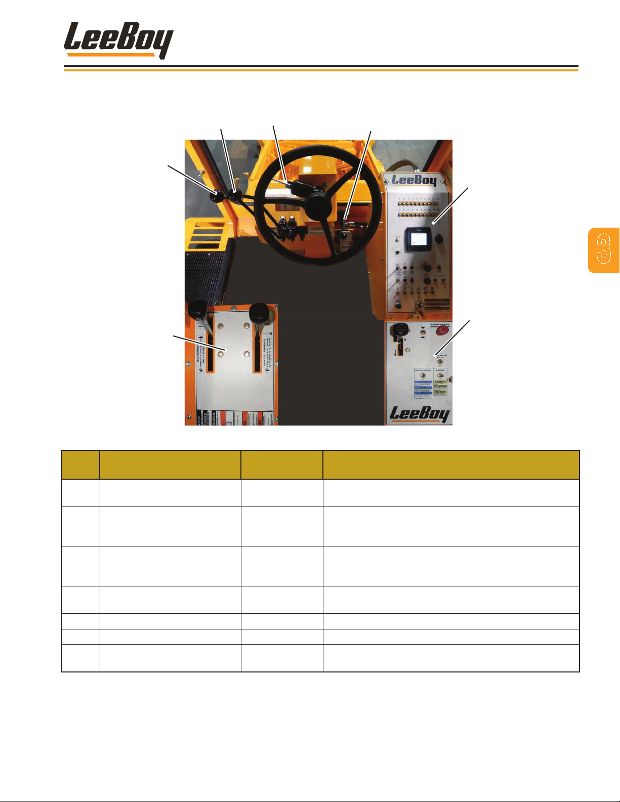
CONTROL CONSOLES
4
Component Location
3
2
5
6
3
7
1
Figure 4-7. Location of Controls
ITEM
NO.
1
2 Moldboard Lift Control Lever Lever
3 Conveyor Lift Control Lever Lever
4
5 Tilt Steering Lock Lever Lever Pull to release.
6 Operating Control Panel Gauge Various control gauges.
7 Direction Control Panel Panel
CONTROL NAME TYPE FUNCTION
Conveyor Feeder Control
Panel
Right and Left Turn
Indicator Switch
Lever Contains the feeder and conveyer control levers.
Adjusts position of moldboard. Pushing lever forward
one notch lowers moldboard. Pushing lever completely
forward places moldboard in the oat position.
Adjusts position of conveyor. Pushing lever forward one
notch lifts conveyor. Pushing lever completely forward
places conveyor in oat position.
3-Position,
Lever Switch
Turns on the left or right directional ashers.
Contains direction control, parking brake, drive motor
control, motor lock, emergency stop and gear shift.
3000C Force Feeder Loader 3-3
Page 36
1
2
Main
Conveyor
Lift
Deector
Small Conveyor
Lift (Option)
Small Conveyor
Deector
Small Conveyor
Small Conveyor
Swivel (Option)
3
4
5
6
7
8
9
10
11
12
Component Location
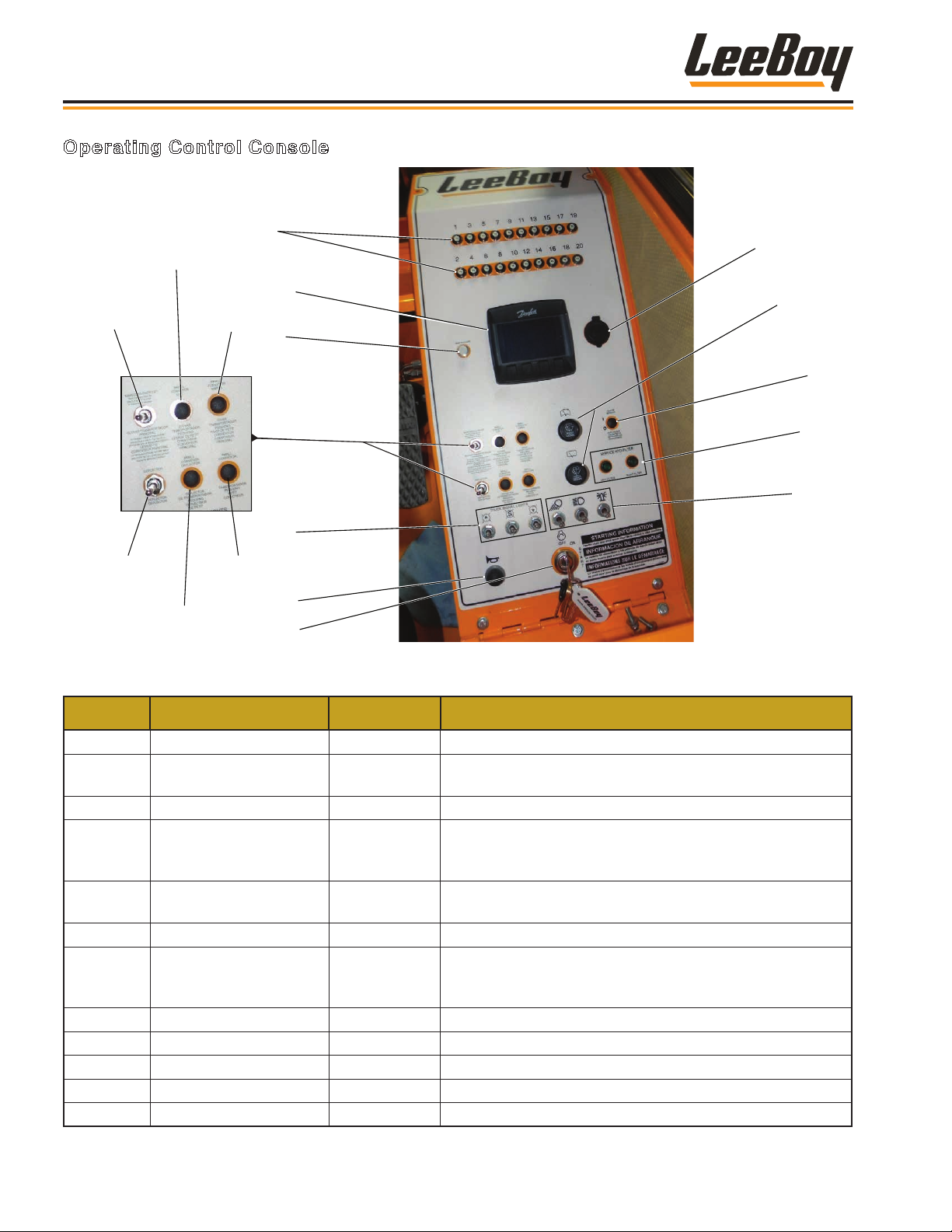
Operating Control Console
Figure 4-8. Operating Control Console
ITEM NO. CONTROL NAME TYPE FUNCTION
1 Reset Buttons Push Buttons Resets for dashboard.
2 DP250 Digital Display Digital Display
3 Wait to Start Indicator Light Indicates engine pre-heat and screen booting.
4 Additional Switches
5 Optional Work Lights Switches
Switches and
Push Buttons
Indicators include: tachometer, fuel level gauge,
temperature gauge, pressure gauge, voltmeter.
Switches/buttons used for operation of the main and small
conveyor lifts; small conveyor, conveyor swivel (Optional),
conveyor lift (Optional), and conveyor deector.
Signal lights used to communicat with the material truck
operator.
6 Horn Push Button Sounds horn.
7 Ignition Key Switch
8 12-Volt DC Outlet Outlet Standard 12VDC automotive-style power receptacle.
Key-Operated
Rotary Switch
Starts and stops engine. Full clockwise is START.
Automatic return to center position when key is released.
Full counterclockwise position is OFF.
9 Windshield Wipers Rotary Switch Operates front and rear windshield wipers.
10 Heated Mirror Push Button Turns heat for mirrors on and off.
11 Service Hydraulic Filters Indicator Light Illuminates when lter(s) need service.
12 Lights Switches Turns lights on and off.
3000C Force Feeder Loader3-4
Page 37
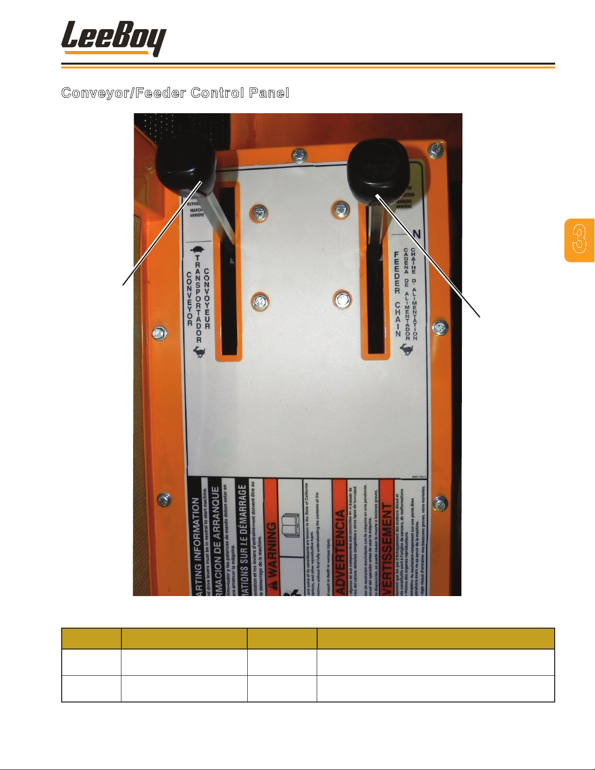
Conveyor/Feeder Control Panel
1
Component Location
3
2
Figure 4-9. Conveyor/Feeder Control Panel
ITEM NO. CONTROL NAME TYPE FUNCTION
1 Conveyor Lever Lever
2 Feeder Lever Lever
3000C Force Feeder Loader 3-5
Pull backwards to set speed of belt. Push forward to
reverse travel of belt.
Pull backwards to pick up material to put on belt. Push
forward to reverse travel of chain.
Page 38
Component Location
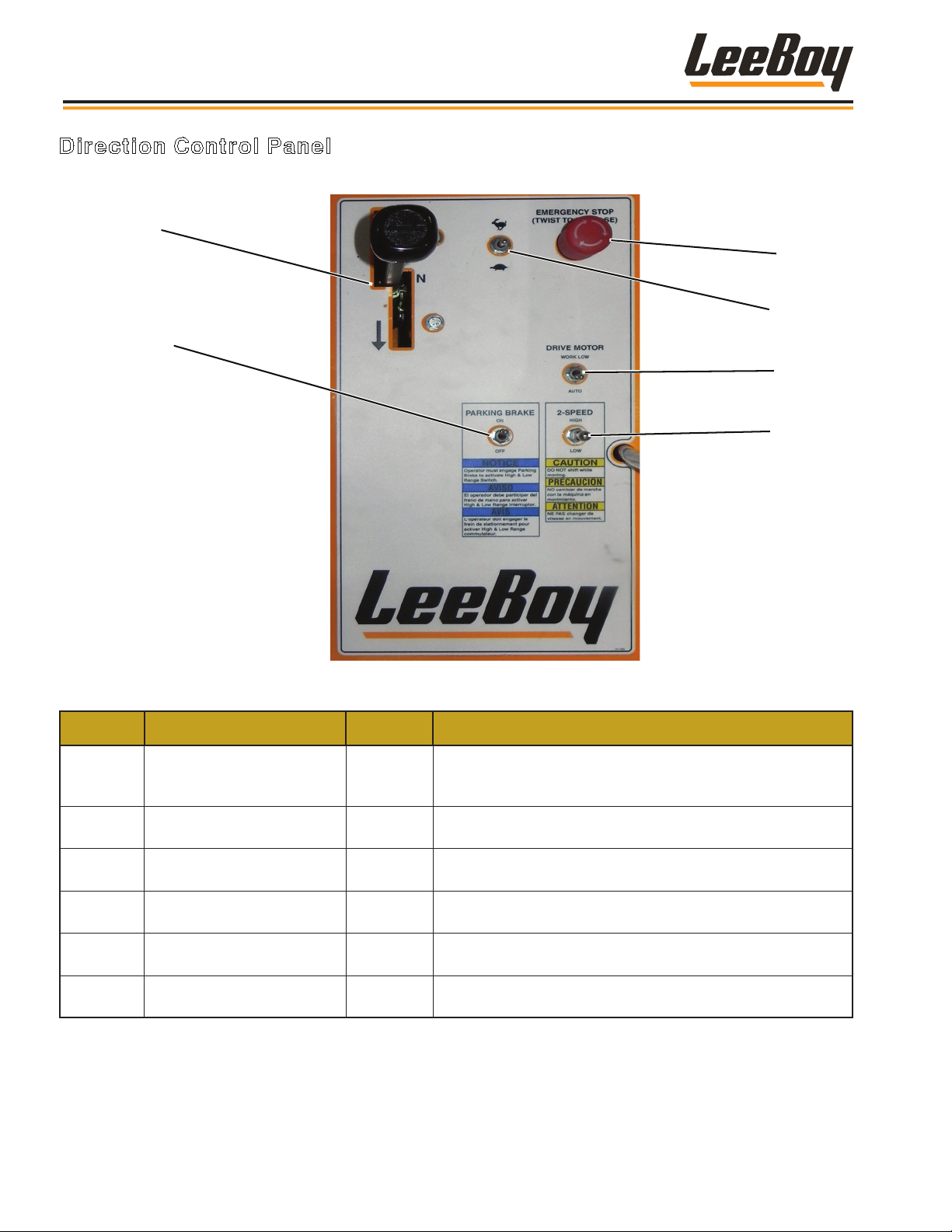
Direction Control Panel
1
2
3
4
5
6
Figure 4-10. Travel Control Panel
ITEM NO. CONTROL NAME TYPE FUNCTION
Sets direction of travel. Center position is NEUTRAL. Speed
1 Directional Lever Lever
2 Parking Brake Switch
3 Emergency Stop
4 Throttle Switch
5 Drive Motor Switch Controls motor torque. Can be used while in motion.
6 2-Speed Gear Shift Switch Forward position is high gear; back position is low gear..
Push/Pull/
Turn
increases as the lever is moved further forward or backward.
Turns parking brake on and off. Machine must be stopped
and parking brake applied.
Press to deactivate the machine. Twist clockwise to release.
Must release to allow function
Controls engine RPMs. Move forward to increase; backward to decrease RPMs.
3000C Force Feeder Loader3-6
Page 39

Section 4
OPERATION
Page
Section 4 . . . . . . . . . . . . . . . . . . . . . . . . . . . . . . . . . . 4-1
General Information . . . . . . . . . . . . . . . . . . . . . . . . . . . . 4-3
Operating Safety . . . . . . . . . . . . . . . . . . . . . . . . . . . . . . 4-3
Stopping Safety . . . . . . . . . . . . . . . . . . . . . . . . . . . 4-4
Maintenance Safety . . . . . . . . . . . . . . . . . . . . . . . . . 4-4
Pre-Start Inspection . . . . . . . . . . . . . . . . . . . . . . . . . . . . 4-5
Machine Adjustments . . . . . . . . . . . . . . . . . . . . . . . . . . . 4-6
Moldboard . . . . . . . . . . . . . . . . . . . . . . . . . . . . . . 4-6
Feeder Assembly . . . . . . . . . . . . . . . . . . . . . . . . . . 4-6
Cam Roller Assembly . . . . . . . . . . . . . . . . . . . . . . . . 4-7
Feeder Chains . . . . . . . . . . . . . . . . . . . . . . . . . . . . 4-7
Lever Linkages . . . . . . . . . . . . . . . . . . . . . . . . . . . 4-8
Operating Procedures . . . . . . . . . . . . . . . . . . . . . . . . . . . 4-8
Loading Material . . . . . . . . . . . . . . . . . . . . . . . . . . . . . . 4-14
Transporting . . . . . . . . . . . . . . . . . . . . . . . . . . . . . . . . 4-14
Towing . . . . . . . . . . . . . . . . . . . . . . . . . . . . . . . . . . 4-15
3000C Force Feed Loader
Start-Up Procedure . . . . . . . . . . . . . . . . . . . . . . . . . 4-8
Selecting High or Low Speed . . . . . . . . . . . . . . . . . . . . 4-10
Forward And Reverse . . . . . . . . . . . . . . . . . . . . . . . . 4-10
Braking . . . . . . . . . . . . . . . . . . . . . . . . . . . . . . . 4-11
Stopping The Engine . . . . . . . . . . . . . . . . . . . . . . . . . 4-11
Operating Conveyor Belt . . . . . . . . . . . . . . . . . . . . . . . 4-11
Conveyor Belt Centering . . . . . . . . . . . . . . . . . . . . . . . 4-12
Lift and Lower Conveyor . . . . . . . . . . . . . . . . . . . . . . . 4-12
Swivel Conveyor (Option) . . . . . . . . . . . . . . . . . . . . . . 4-13
4-1
Page 40

Operation
NOTES
3000C Force Feed Loader4-2
Page 41

Operation
GENERAL INFORMATION
This section provides the operating instructions for
the LeeBoy Model 3000C Force Feed Loader. It is
important to read, understand, and follow all precautions,
operating instructions and warnings in this manual
before starting or operating the machine.
Failure to observe the operating
precautions and warning instructions could cause
serious injury or death. Only authorized personnel
who are properly trained should operate the LeeBoy
Model 3000C Force Feed Loader.
This machine should be kept in good
mechanical condition at all times.
DO NOT operate a machine that is
in need of repair. Put an information tag on the
instrument panel that says “DO NOT OPERATE.”
Remove the key from the ignition switch. Repair all
damage promptly as even minor damage can result
in major system failures.
The operator must understand the
function of all controls, indicators and gauges before
starting the engine. Serious injury or death can
result if these procedures are not followed.
Refer to Section 3 for a list of controls and a description
of their functions.
Daily inspection and servicing
at required intervals are necessary for the
safe operation and maximum service life of the
LeeBoy Model 3000C Force Feed Loader and its
components.
OPERATING SAFETY
• ALWAYS ensure no person or object is in the line of
travel before starting the machine.
• Work slowly in tight areas.
• DO NOT run engine in a closed building for long
periods of time.
• Avoid steep hills if possible.
• ALWAYS look before changing the direction of travel.
• Avoid leaving engine running without operator
present.
• Keep hands, feet and clothing away from powerdriven parts.
• DO NOT wear loose jackets, shirts, sleeves or other
items of clothing due to the danger of entanglement in
moving parts.
• With the engine running, check both the service and
parking brakes to ensure proper working condition.
• DO NOT hold onto the steering wheel as a handle
when getting in or out of the vehicle.
• Keep hands, oors and controls free from water,
grease and mud to prevent falls.
• Only start and operate the loader from the operator’s
platform.
• ALWAYS keep the loader in gear when moving down
steep hills.
• When transporting or driving, use accessory lights
and devices for adequate warning to other vehicles.
Check local government regulations.
4
• DO NOT oil, grease or adjust any part of the loader
while it is in motion.
• Check for faulty wiring or loose connections.
• Keep a rm grip on the steering wheel at all times,
especially when speed is increased.
• DO NOT allow anyone near the loader while the
engine is running.
• Reduce speed before turning or applying brakes.
• Drive at speeds slow enough to ensure your safety,
especially over rough terrain, hills and curves.
• Be sure the path ahead is clear to avoid collision with
other machines.
3000C Force Feed Loader 4-3
Page 42
Operation
• Watch for overhead wires. Never touch wires with any
part of the loader.
• Keep the working area as level as possible.
• NEVER allow anyone to work under a raised conveyor
or other attachment.
• ALWAYS lower conveyor and moldboard when
machine is not in use.
• Be sure that bystanders are clear of the loader before
lowering or moving conveyor and other attachment.
• Park loader on level ground or across the slope.
DO NOT smoke when performing
inspections or servicing unit.
Stopping Safety
• ALWAYS park the loader on solid, level ground. If this
is not possible, park the loader at a right angle to the
slope.
• ALWAYS lower the moldboard and conveyor when
leaving the machine unattended.
periods of time.
• Add coolant to the radiator only when the machine is
stopped or idling slowly. To avoid being scalded when
the pressure ller cap is being removed, turn the cap
slightly to relieve pressure before removing the cap.
• DO NOT leave the engine running while making
adjustments or repairs unless specically
recommended in this manual.
• NEVER allow anyone to work under a raised conveyor
or other attachments.
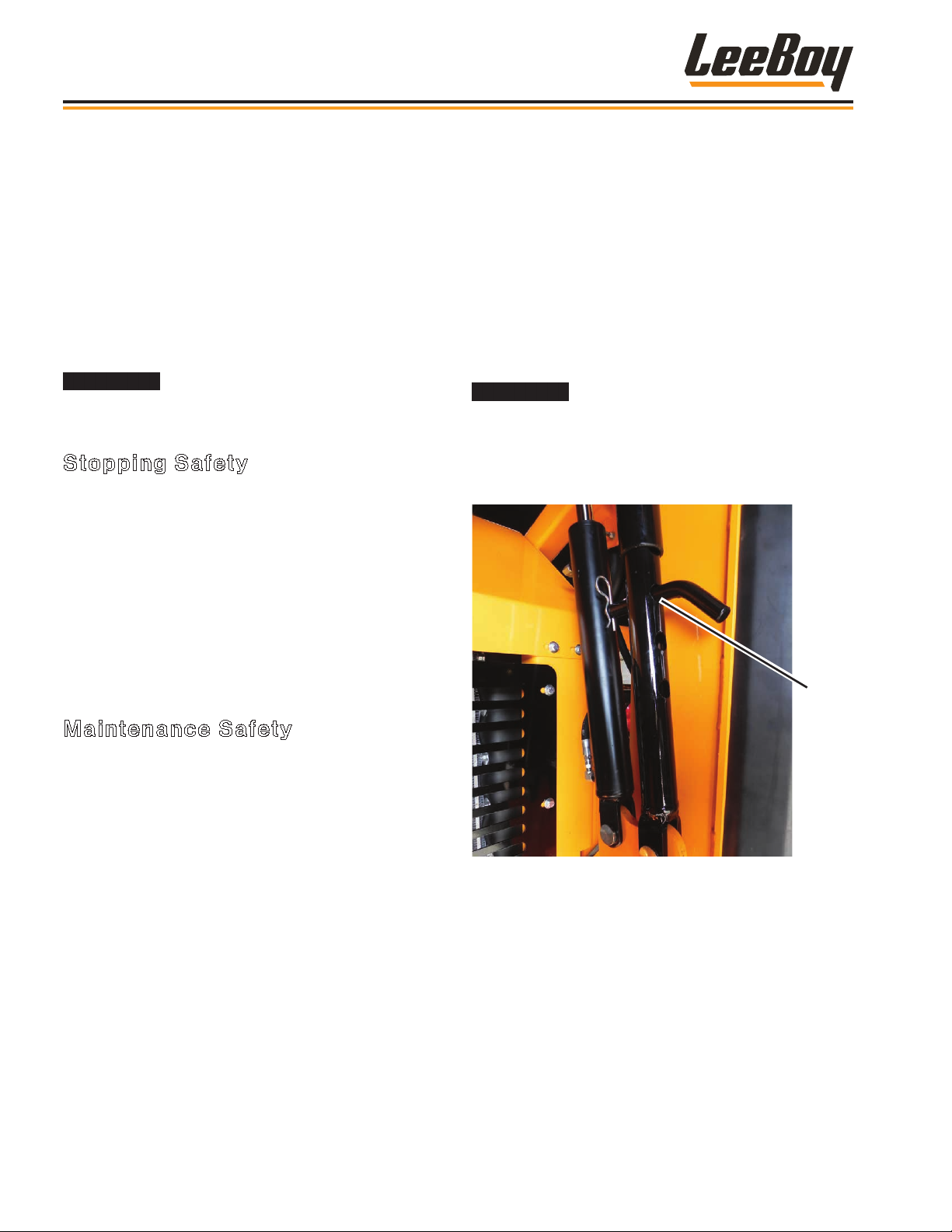
Never work under the conveyor
without placing safety pins in position. One pin must
be inserted into each conveyor support on each side
beneath the conveyor. When removing pins, be sure
to replace in the stored position above the cylinders.
(Figure 4-1)
• ALWAYS engage parking brake when parking or
leaving the machine unattended.
• Use proper ags, barriers and warning devices,
especially when parking in areas of trafc.
Maintenance Safety
• NEVER work on the loader while the engine is running.
• NEVER refuel while the engine is running. DO NOT
smoke while lling the fuel tank or servicing the
machine.
• DO NOT change the engine governor settings.
• ALWAYS replace damaged or lost decals.
• Disconnect battery by using the the disconnect winch
when working on the electrical system or welding on
the unit.
• If charging battery with a charger, ensure battery
charger is off when making connections.
• Be sure to observe the correct battery polarity
when connecting a battery charger or jumper cable:
Negative (-) to negative (-) and positive (+) to positive
(+).
Safety
Pin
Figure 4-1. Safety Pin Properly Inserted
• Work slowly in tight areas.
• DO NOT run engine in a closed building for long
3000C Force Feed Loader4-4
Page 43
Operation
PRE-START INSPECTION
The operator should inspect the machine thoroughly
before each use. Visually inspect the unit for
familiarization and to check its general condition.
Continue with a check of special systems and
components. Daily inspections will maintain the life and
reduce maintenance costs for your LeeBoy 3000C
Force Feed Loader.
Table 1-1. Operator Inspection List
INSPECTED ITEM PROCEDURE
Hydraulic
Fuel Check fuel guage on the gauge panel for fuel level and ll if needed.
Engine Oil
Radiator Check the coolant level.
Battery
Air Cleaner
Planetary Axle Check oil level. Drain and replace after the rst 50 hours of operation.
Tire Pressure Check for proper ination. (45 PSI Rear and 90 PSI Front.)
Drain Plugs Make sure plugs are installed and tight.
Engine Belt Check for proper tension of belt. Check for wear and replace if needed.
Grease Fittings Make sure the ttings are greased and in good working order.
Lug Nuts Make sure lug nuts are tight and torqued to the correct value.
Front Axle Pin and cotter key and all bolts.
Conveyor Belt Ensure the conveyor belt is centered.
Pump Box
Check hydraulic oil level and ll if needed using Citgo All-Temp. Inspect the tank for any
leaks.
The engine oil level is measured on the right side of the engine. Open the access door to
access dipstick. Make sure oil is clean and falls between the two marks on the dipstick.
Use 15W40 if needed to ll.
Check cables for damage. Ensure cables are tight and clean. Check for corrosion on the
battery terminals and clean if needed.
Check the air lter element and hose connections. Air cleaner has both a primary and
secondary lter. If the air cleaner indicator is red, the air lters need replacement. Reset
the indicator by pressing the button on top of it.
Check pump box oil level using the dipstick on rear side of the engine. Oil level should be
lled to the top of the knurled surface.
• Ensure that all the instruction and safety decals are in
place and legible.
• Ensure operator’s area is free from debris.
• ALWAYS wear OSHA required safety equipment when
operating the loader.
• Be sure that any malfunctioning, broken, worn or
missing parts are repaired or replaced before
operating the machine.
4
3000C Force Feed Loader 4-5
Page 44
Operation
MACHINE ADJUSTMENTS
Moldboard
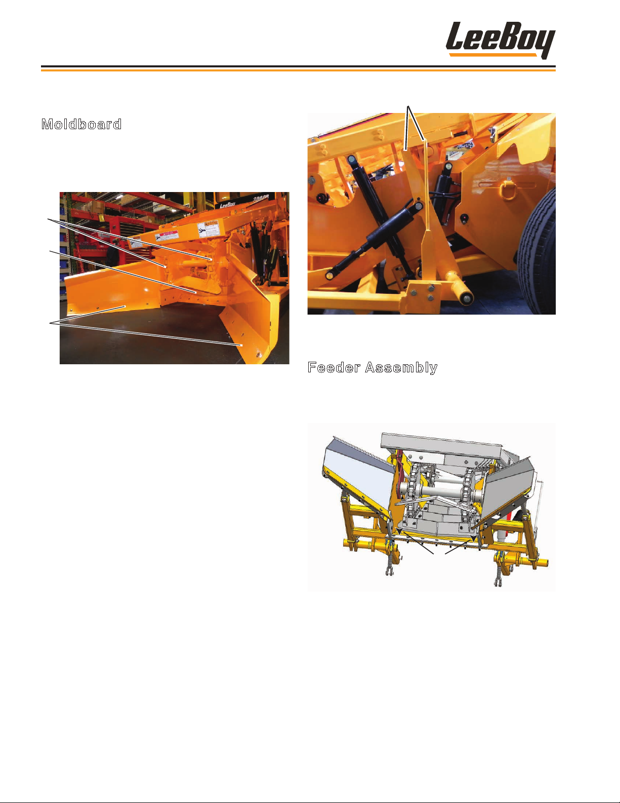
It is important to set-up the moldboard before operating
the loader. Check the adjustments daily to ensure there
is no interference between the moldboard and the
feeder chain assembly. (Figure 4-2)
1
2
3
Figure 4-2. Moldboard and Feeder Chain Assembly
1 - Feeder Chains
2 - Feeder Plate
3 - Cutting Edges
Pointers
Figure 4-3. Moldboard Pointers
Feeder Assembly
Adjust the feeder assembly to a height of approximately
two inches off the transition plate using the following
procedure (Figure 4-4):
You will need to adjust both the feeder assembly and the
cam roller assembly to set up the moldboard properly.
To prepare machine for these adjustments:
1. Park machine on a at surface.
2. Raise the rear of the main conveyor into the work
position using the main conveyor lift switch on the
operating control console. (Page 3-3)
3. Insert safety pins to desired operating height.
(Page 4-4)
4. Using the conveyor and moldboard lift control levers
(Page 3-4), lower the cutting edges so that all ve
cutting edges are at on the ground. (Figure 4-2)
5. Align the the moldboard pointers. (Figure 4-3)
2”
Figure 4-4. Feeder Assembly Height
1. Lift front of feeder using a lifting hoist.
2. Loosen jam nuts on both sides of the feeder
assembly support rods. (Figure 4-4)
NOTE: Ensure cam rollers are not touching while
making this adjustment.
3000C Force Feed Loader4-6
Page 45
Nuts
Operation
3. Turn nuts on both sides of machine the same
amount, keeping the feeder level.
4. Lock jam nuts.
5. Lower the feeder and check measurement.
6. Repeat to get the correct height between the feeder
blades and the transition plate.
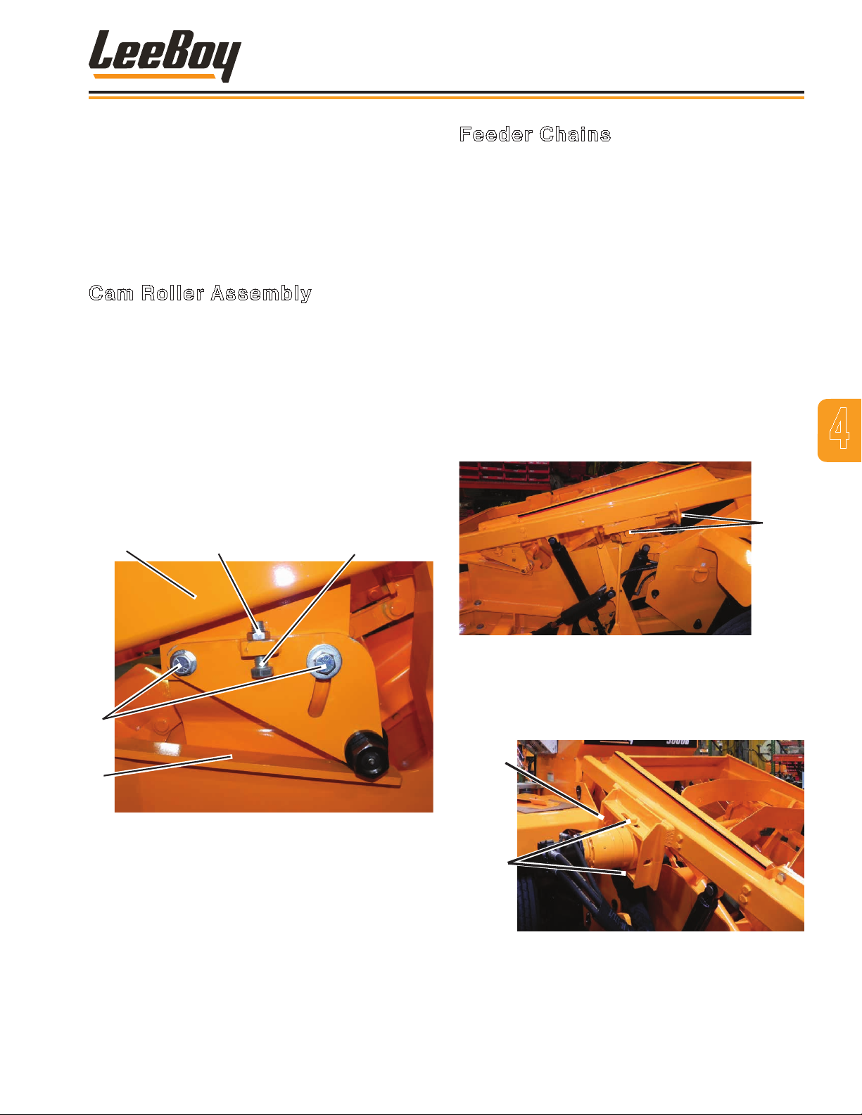
Cam Roller Assembly
Adjust the cam roller assembly using the following
procedure (Figure 4-5):
1. Loosen both outer bolts.
2. Loosen the adjustment bolt.
3. Using a pry bar, raise the roller about 1/2-inch clear
of the rail.
4. Tighten outer bolts securely to attach bracket into
place.
5. Adjust adjusting bolt until touching the frame.
6. Tighten jam nut securely to fasten bolts into position.
Feeder Chains
The feeder chains pick up material and dump it onto the
discharge conveyor belt. (Figure 4-2)
The feeder chain lever is located on the left side of the
operator’s station and controls the speed of the feeder
chain. Pushing the feeder chain lever to neutral slows
and stops the feeder chain. Pushing it forward reverses
the feeder chain. (Page 3-6)
The two chains for the feeder assembly must be
adjusted to provide one inch of “play” for proper
operation.
Perform this adjustment as follows:
1. Check the amount of play in the chains by pulling
up on the center of the chain and check for
approximately one inch of play. If the play is correct,
no adjustment is required. If the chain has too much
slack, proceed with Step 2.
4
3
2
1
Figure 4-5. Cam Roller Assembly on Transition
1 - Rail
2 - Outer Bolts
3– Frame
4 - Jam Nut
5 - Adjusting Bolt
4
Plate
5
Figure 4-6. Feeder Chain Bracket and Bearing
2. Loosen the nuts securing bracket and bearing.
(Figure 4-6)
3. Loosen the jam nut of screw.
Jam
Nut
Bolts
Figure 4-7. Drive Side of Feeder Chain
4. On the drive side, loosen the bolts securing the top
and bottom of the torque hub mount . (Figure 4-7)
3000C Force Feed Loader 4-7
Page 46
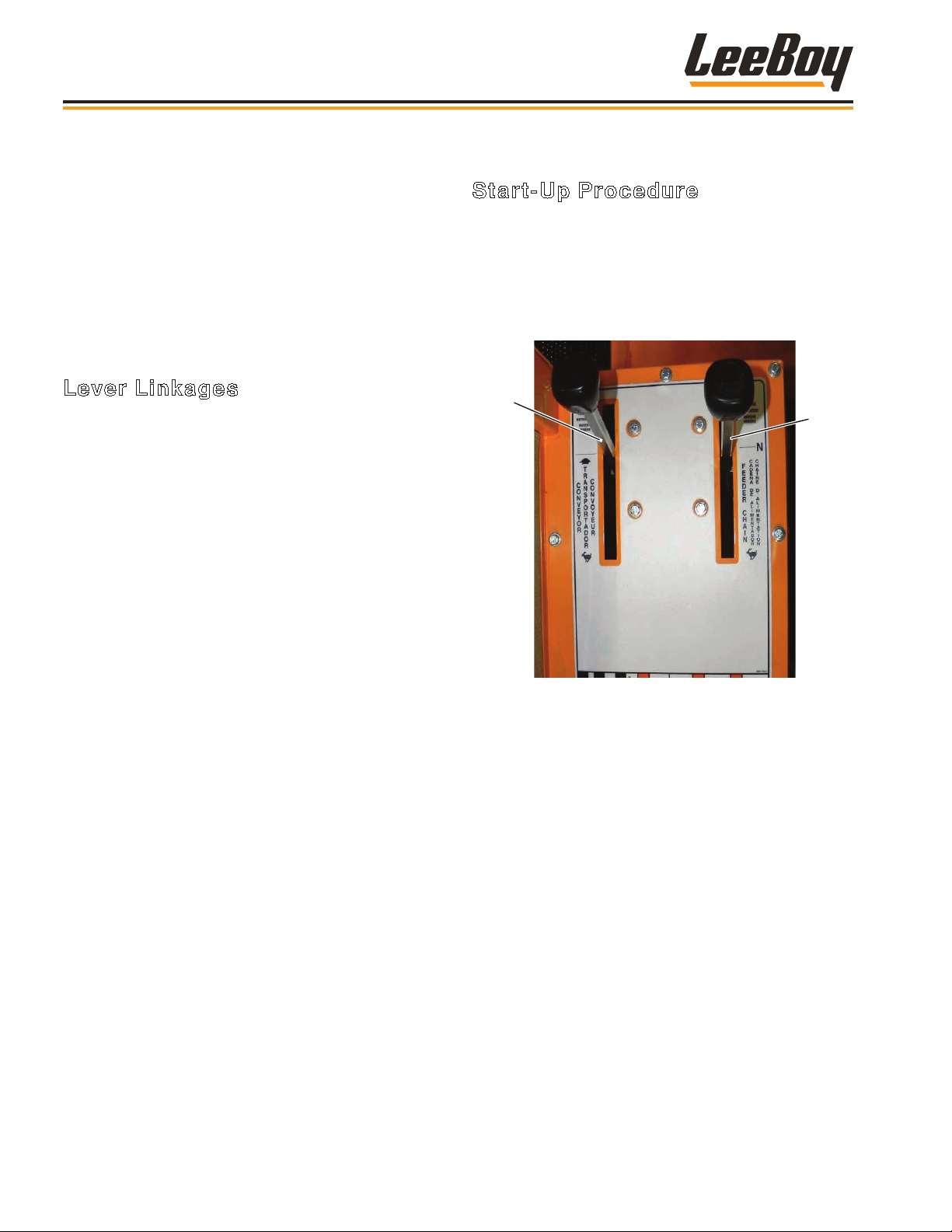
Conveyor
Feeder
Chain
Operation
5. Loosen the jam nut on the adjusting screw for the
drive side.
6. Adjust both screws the same amount, trying to keep
both shafts in line with each other and to get the one
inch of play required.
7. Tighten jam nuts.
8. Tighten mounting bolts.
9. Recheck the chain for approximately one inch of
slack. If necessary, repeat the procedure.
Lever Linkages
All lever linkages can be adjusted by loosening the jam
nut on the rod end, then adjusting position of the rod
end. Be sure after making adjustments that the jam nuts
are tightened against the rod ends.
OPERATING PROCEDURES
Start-Up Procedure
NOTE: The engine will not start unless the
conveyor, feeder chain and directional
control levers are all in the NEUTRAL
position, and the E-Stop button is released.
1. Check that conveyor lever and feeder chain lever
are both in the neutral (N) position. (Figure 4-8)
Figure 4-8. Conveyor and Feeder Levers
2. On the direction control panel, turn the parking
brake switch to the ON position. (Figure 4-9)
3. Ensure the direction control lever is in the neutral
(N) position. (Figure 4-9)
3000C Force Feed Loader4-8
Page 47
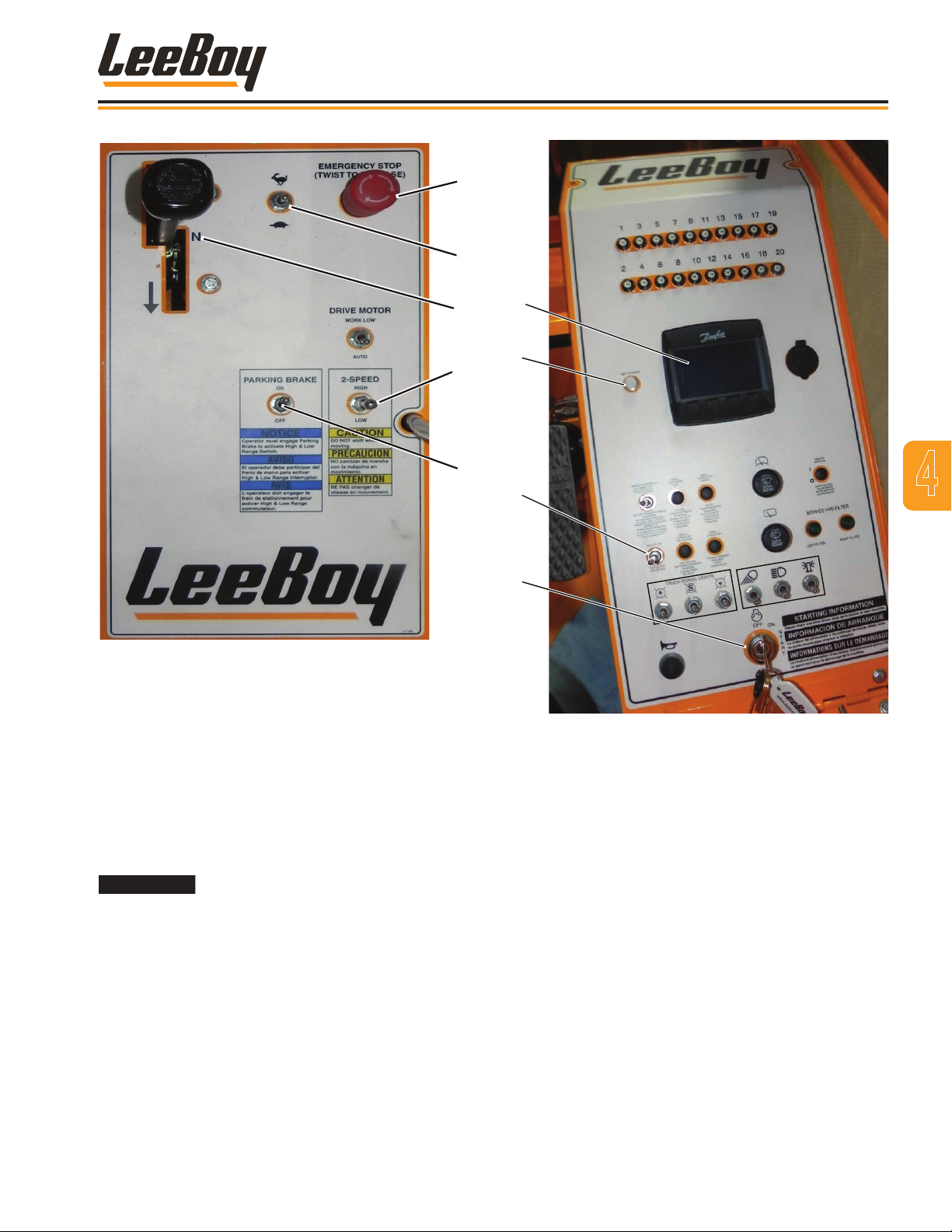
Operation
1
2
Figure 4-9. Direction Control Panel
1 - Emergency Stop
2 - Throttle Switch
3 - Direction Control Lever
4 - 2-Speed Gear Switch
5 - Parking Brake
4. Insert key and turn ignition clockwise to the Start
position. Wait until the “Wait to Start” light turns off
to crank the engine. (Figure 4-10)
3
4
5
1
2
3
4
Figure 4-10. Operating Control Console
1- DP250 Digital Display
2 - Wait to Start Light
3 - Deector Switch
4 - Ignition Switch
4
If engine does not start, release key
and wait at least two minutes before trying to starting
again. DO NOT leave key in the start position more
than 30 seconds.
3000C Force Feed Loader 4-9
Page 48
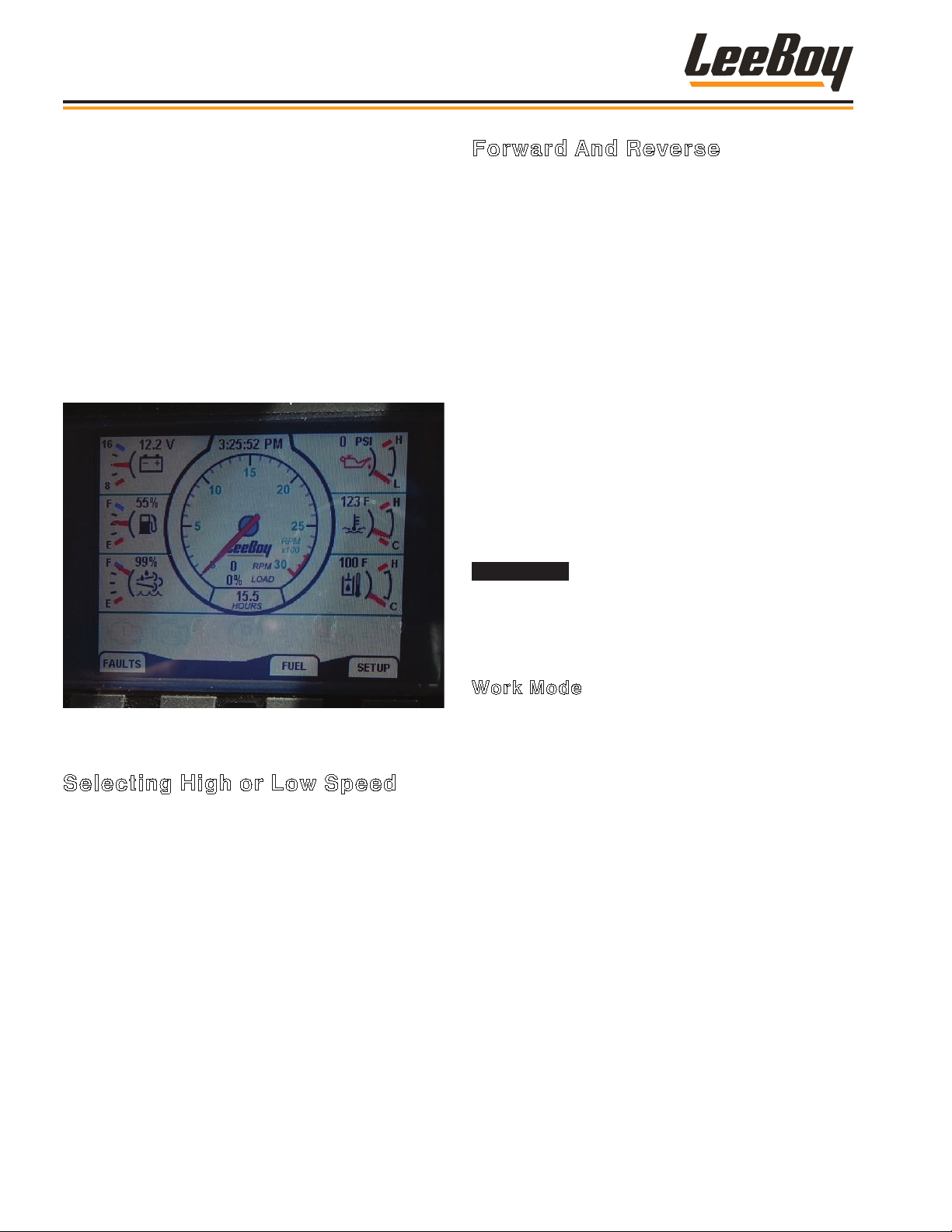
Operation
5. The DP250 Digital Display on the Operating
Control Console will illuminate, rst displaying
the LeeBoy logo as the system “boots,” followed
by the indicators. These indicators include the
tachometer, fuel level, temperature gauge, pressure
gauge and voltmeter. (Figure 4-11)
• The SETUP softkey function allows you to set
the screen contrast, clock and other convenient
functions.
• Touch the FAULTS softkey if it or the WARN
light illuminates to see what component needs
attention (i.e., coolant level low, engine oil
pressure low, and any other system fault).
Forward And Reverse
Before driving on public roads, check state and local
laws that may apply to tractors, self-propelled machines,
and towed equipment. Additional lights, mirrors, slowmoving vehicle emblems, or reectors may be required.
The LeeBoy 3000C Force Feed Conveyor Loader
is equipped with a Forward/Reverse variable speed
hydraulic motor that has a two-speed rear-end. The
directional control lever controls the speed and
direction of the hydraulic pump. (Figure 4-8)
Travel Mode
• Travel speed is determined by setting the drive motor
switch to AUTO; set engine RPMs to the desired
speed; and the 2-Speed gear shift switch to the HIGH
speed position .
• The farther you move the directional lever either
forward or backward, the faster the machine will travel
in that direction.
When using the 2-Speed gear switch
to change speed, the vehicle must be stopped and
the direction control lever set to the NEUTRAL
position.
Figure 4-11. DP250 Digital Display Screen
Selecting High or Low Speed
The 2-Speed gear switch selects high or low speed.
It is located below the throttle on the right side of the
operator control console. (Figure 4-8)
After starting engine (using the previous procedures)
• On the travel control panel, turn the parking brake
switch to the ON position.
• Shift the High/Low toggle to the gear desired. Hold for
two seconds, then return to center.
• Turn the parking brake switch to OFF and ensure the
gear changed by slowly moving forward and backward
to ensure engagement.
Work Mode
The Drive Motor switch on the travel control panel has
two settings: Work Low and Auto. (Page 3-6)
When working at the job site, follow these procedures
for moving forward and reverse:
• Shift the machine into low gear using the 2-Speed
gear shift switch.
NOTE: ALWAYS use the LOW speed position on the
2-Speed gear shift when working.
• Set desired engine RPM.
• Setting the drive motor switch to AUTO allows the
machine to grade at the fastest possible speed with
load.
• Setting the drive motor switch to Work Low allows the
machine to stay at a steady speed, varying only when
using the foot pedal.
3000C Force Feed Loader4-10
Page 49
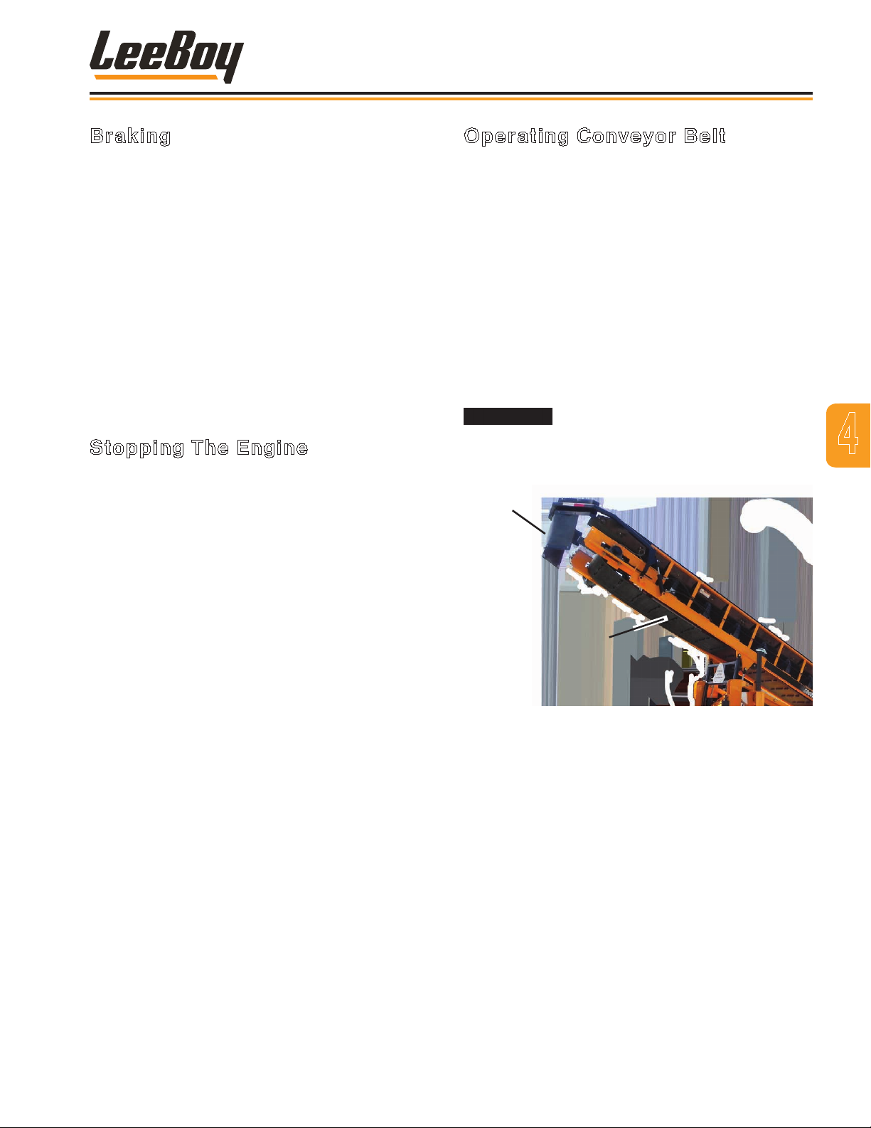
Operation
Braking
Braking is accomplished by returning the Forward/
Reverse Directional Control lever to NEUTRAL (center
position). As the lever is moved toward NEUTRAL, the
speed of travel will slow, allowing the operator to choose
the speed desired. The foot brake maybe also be used
to slow the machine.
The LeeBoy 3000C Force Feed Loader is equipped
with a parking brake located to the right of the operator
beside the 2-Speed gear switch. This brake should only
be used for emergency stopping, parking or changing
between high or low gears. (Figure 4-8)
• To engage the brake, ip switch to the ON position.
• To release the brake, ip switch to the OFF position.
Stopping The Engine
1. Move the direction lever to the NEUTRAL position.
2. Stop machine motion by pressing on the brake
pedal.
3. Move throttle lever to the minimum RPM (turtle)
position.
Operating Conveyor Belt
To raise and lower the conveyor on the rear of the
machine, use the main conveyor lift switch on the
operating control console. (Page 3-4)
The belt speed is controlled by the engine speed and
how far the conveyor lever is advanced from neutral.
(Figure 4-8)
When the lever is pulled backward, the belt will move
to discharge material to the swivel or truck. By moving
the lever forward, the belt will run in reverse to free up a
clogged belt.
The deector hydraulically tilts, raises and lowers to
direct the material ow into the receiving truck or other
intended location.
Never use hands to free a clogged
belt. Keep clothing and hands away from moving
belt.
Deflector
4
4. Flip the parking brake switch to the ON position.
5. Turn ignition key on instrument panel counterclockwise to the OFF position and remove key.
Conveyor
Belt
Figure 4-12. Conveyor Belt
3000C Force Feed Loader 4-11
Page 50

Operation
Conveyor Belt Centering
The conveyor belt must be kept centered at all times.
This should be checked daily.
NOTE: The distance must be the same on both
sides of the belt.
The machine must be parked and shut
off with all attachments lowered.
Be sure to insert safety pins before
making adjustments. (Page 4-4)
To center the conveyor belt:
1. Measure the distance from both sides of the belt to
the frame. (Figure 4-13)
2. Determine which side of the belt is closest to the
frame. The adjustment will be made on that side of
the belt. If the closest is the drive side, proceed with
Step 3. If the closest is on the bearing side, skip to
Step 8.
5. Allow conveyor to run several minutes, then recheck
measurements.
6. If belt is not centered, adjust in the opposite
direction accordingly, or repeat Steps 3 and 4.
7. If belt is centered, tighten the jam nut and the top
and bottom cap screws.
8. Loosen bearing support cap screws so the bearing
position can be changed.
9. Loosen the lock nut and adjust bolt as needed.
10. If belt is still not centered, repeat Steps 8 and 9. If
belt off center, adjust in the opposite direction.
11. If belt is now centered, repeat Step 7.
Lift and Lower Conveyor
Lift and lower the discharge conveyor (rear) using
the conveyor switch on the console to the right of the
operator’s station. (Page 3-4)
This is a three-position lever (the center position is
OFF). When the lever is moved forward to the UP
position, the conveyor is raised. When the switch is
moved rearward to the DOWN position, the conveyor is
lowered.
Figure 4-13. Centering Measurement
3. Loosen cap screw on the top and bottom of the
drive assembly.
4. Loosen the jam nut and adjust position of drive by
adjusting screw.
Raise the front of the conveyor using the conveyor lever
located on the left side of the operator control console.
(Figure 4-8)
The conveyor must be raised high
enough to allow a truck to be positioned underneath.
Always lower the conveyor when traveling.
If working under the conveyor, be sure
to insert the safety pins into the cylinders to prevent
injury. (Page 4-4)
3000C Force Feed Loader4-12
Page 51
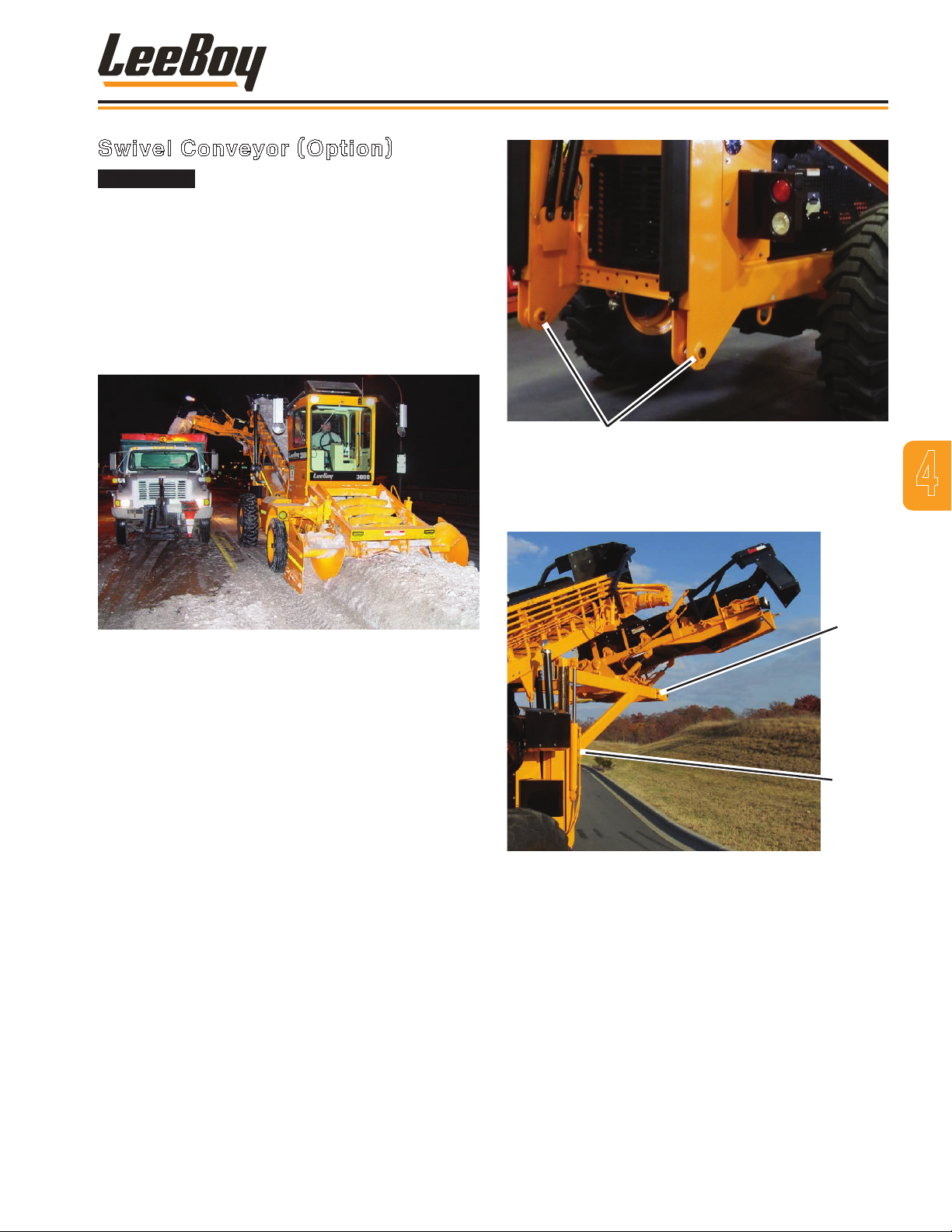
Swivel Conveyor (Option)
The main conveyor must be fully
raised with the safety pins inserted in the conveyor
supports before operating the swivel.
The operational swivel conveyor gives the operator the
ability to direct material to the right, left or rear of the
machine. The swivel conveyor can move anywhere in
a 180-degree angle from the main conveyor, directing
material wherever you want it to go. This feature allows
the receiving truck to travel beside the loader in the
same direction as it receives material. (Figure 4-14)
Operation
Pins
Figure 4-15. Locking Pins
4. Lower swivel assembly slowtly to take the weight off
locking pins. Remove locking pins. (Figure 4-16)
4
Figure 4-14. Swivel Conveyor on Job Site
The operator will need to become familiar with using the
swivel conveyor as the main conveyor could overload
the swivel if operating too fast. The swivel conveyor
switch is on the console to the right of the operator’s
console. (Page 3-4)
The swivel conveyor is factory-installed, but it can be
removed and reinstalled as needed. To remove the
component:
1. Park the loader on a level surface. This is critical for
ensuring the assembly is stable once removed.
2. Raise rear main conveyor and install safety support
pins. (Page 4-4)
3. Raise the swivel assembly high enough to install the
rear long leg stands. (Figure 4-16)
Long
Leg
Short
Leg
Figure 4-16. Leg Stands
5. Raise the swivel assembly high enough to install the
short leg stands.
6. Lower the swivel assembly again so the mounting
hooks clear the frame.
7. Remove all swivel assembly connection hoses from
the hydraulic bulkhead. Be sure to label each hose
for its location for ease of reinstalling. (Figure 4-17)
3000C Force Feed Loader 4-13
Page 52
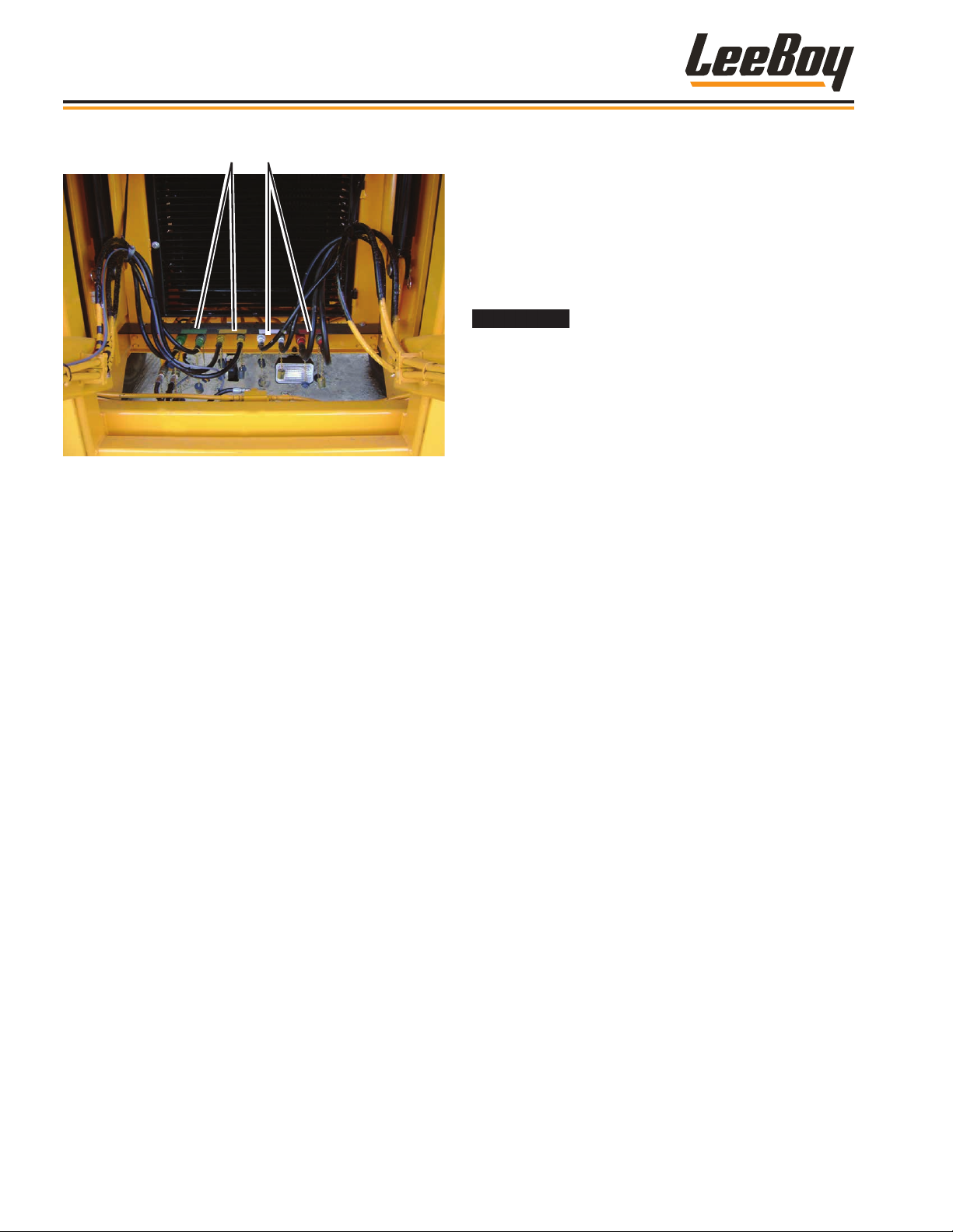
Operation
Hoses
Figure 4-17. Connection Hoses
8. SLOWLY drive the loader away from the swivel
assembly.
9. Reinstall the two locking pins for use during
reassembly.
To reinstall the assembly, simply reverse the steps
above.
10. Pull discharge conveyor lever to full speed, unless
using swivel conveyor.
11. Using the direction lever, move forward into the
material. Be sure not to overload the belt.
12. Using the conveyor lever, raise and lower the
front of the conveyor as needed, ensuring the
moldboards are at on the ground while keeping the
moldboard lever in oat.
ALWAYS watch out for overhead
obstacles while operating conveyor.
13. The deector may be used to position the material in
the material truck or where desired.
14. For quick stopping, apply the foot brake. Release
the brake to resume speed or return the direction
lever to neutral.
TRANSPORTING
When transporting the loader on a trailer, the vehicle
should be large enough to safely handle the size and
weight of the loader in all driving situations.
1. Park the loader on a level surface engage the park
brake.
LOADING MATERIAL
1. Raise conveyor to work height. (For better
performance of the belt tracking, place support pins
in holes in the rear stabilizer).
2. Set the deector to the desired position. (Figure
4-10)
3. Using the moldboard lever, align the pointers on the
moldboard.
4. Using the conveyor lever, SLOWLY oat the
moldboards down until they touch the ground and
take lever out of oat.
5. Return to the conveyor lever, lifting the moldboards
so they are slightly touching the ground.
6. Place the moldboard lever in oat at this time. (This
will put the minimum amount of weight on the cutting
edges for prolonged life).
7. Align truck with conveyor.
8. Set RPM to desired speed (full RPM for maximum
production).
9. Pull the feeder chain lever to desired speed.
2. Block the wheels in both directions so the loader
will not roll.
3. Lower the deector, conveyor and cutting edges.
4. Switch the machine to low gear using the 2-Speed
gear switch on the travel control panel. (Page 3-7)
5. Load the machine onto the trailer.
6. Block the wheels in both directions.
7. Use enough chains with the strength to secure the
loader, ensuring it will not move during transport.
Connect chains to the factory-installed D-Ring tie
downs provided on various areas of the machine for
transporting purposes. (Figure 4-14)
3000C Force Feed Loader4-14
Page 53
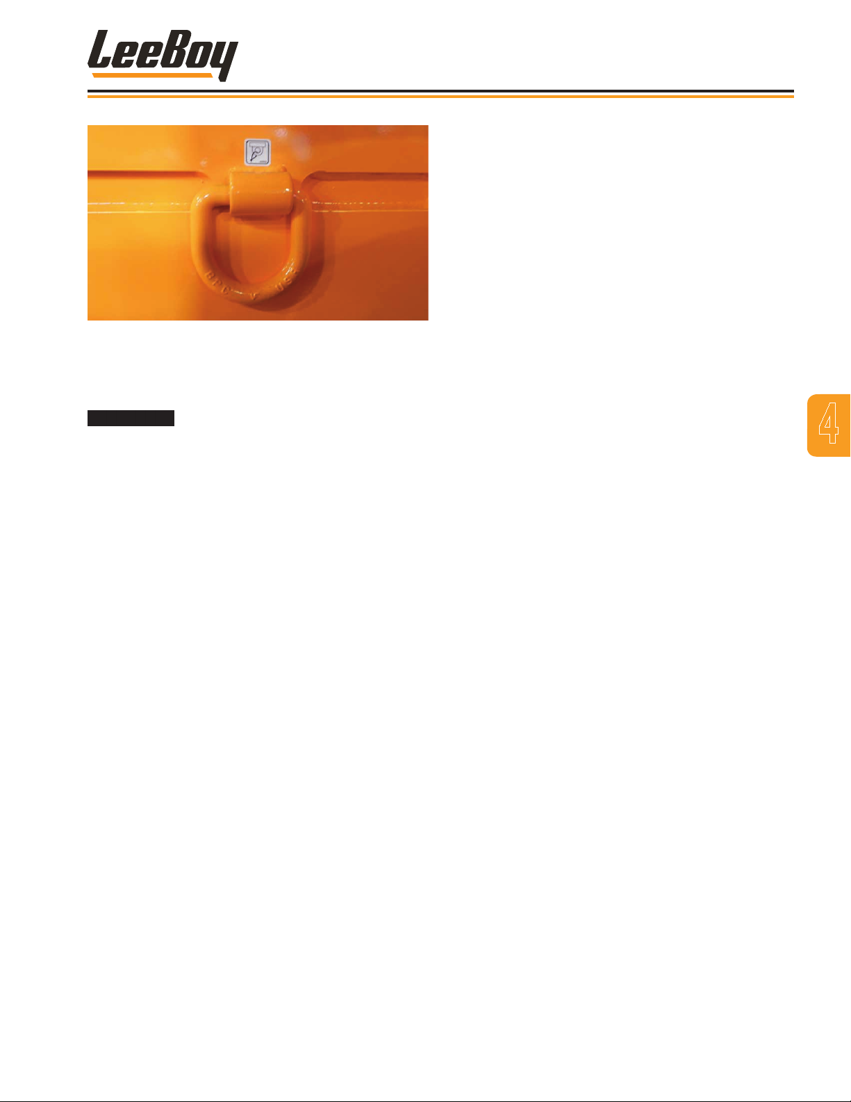
Figure 4-18. D-Ring Tie Down
TOWING
Wheels must be blocked to prevent
machine from moving while preparing machine for
towing.
Operation
4
Prepare the machine for towing as follows:
1. Block wheels to prevent machine from moving.
2. Unhook hoses on shifter and plug hoses.
3. Using a small pry bar, manually pull shifting lever at
front of rear-end until it is fully extended.
4. Now push the lever back in.
5. Find center position to disengage gears for towing.
6. On the sides of the rear-end, locate the screw with a
square head.
7. Using a caliper, measure the exact extension of the
screw. Record measurement.
8. Turn the screw completely in to release the brakes.
To return the machine from towing condition to normal
operation, proceed as follows:
• Push shifting lever at front of rear-end all the
way in.
• Adjust square head screw to the exact position
measured in Step 5 above.
• Reattach hoses to the shifter.
3000C Force Feed Loader 4-15
Page 54

Operation
NOTES
3000C Force Feed Loader4-16
Page 55

Section 5
MAINTENANCE
Page
Maintenance . . . . . . . . . . . . . . . . . . . . . . . . . . . . . . . . . 5-1
General Information . . . . . . . . . . . . . . . . . . . . . . . . . . . . 5-3
Maintenance Schedule . . . . . . . . . . . . . . . . . . . . . . . . . . . 5-4
10-Hour or Daily Routine Maintenance . . . . . . . . . . . . . . . . 5-4
50-Hour Routine Maintenance . . . . . . . . . . . . . . . . . . . . 5-4
100-Hour or Monthly Routine Maintenance . . . . . . . . . . . . . . 5-4
250-Hour or Quarterly Routine Maintenance . . . . . . . . . . . . . 5-5
500-Hour or Semi-Annual Routine Maintenance . . . . . . . . . . . 5-5
1000-Hour or Annual Routine Maintenance . . . . . . . . . . . . . . 5-5
2000-Hour or Annual Routine Maintenance . . . . . . . . . . . . . 5-5
3000-Hour or Annual Routine Maintenance . . . . . . . . . . . . . 5-5
Lubrication Points . . . . . . . . . . . . . . . . . . . . . . . . . . . . . 5-6
Tire Replacement . . . . . . . . . . . . . . . . . . . . . . . . . . . . . 5-7
Cooling System . . . . . . . . . . . . . . . . . . . . . . . . . . . . . . 5-7
Engine Maintenance . . . . . . . . . . . . . . . . . . . . . . . . . . . . 5-8
3000C Force Feed Loader
Radiator Coolant . . . . . . . . . . . . . . . . . . . . . . . . . . . 5-7
Replace Radiator Hoses . . . . . . . . . . . . . . . . . . . . . . 5-8
Check Engine Oil . . . . . . . . . . . . . . . . . . . . . . . . . . 5-8
Change Engine Oil . . . . . . . . . . . . . . . . . . . . . . . . . . 5-9
Change Engine Oil Filter . . . . . . . . . . . . . . . . . . . . . . . 5-9
Air Filter . . . . . . . . . . . . . . . . . . . . . . . . . . . . . . . 5-10
Engine Drive Belt . . . . . . . . . . . . . . . . . . . . . . . . . . 5-10
Crankcase Ventilation Filter . . . . . . . . . . . . . . . . . . . . . 5-11
Diesel Exhaust Fluid (DEF) System . . . . . . . . . . . . . . . . . . 5-11
5-1
Page 56

Maintenance
DEF Tank Filter . . . . . . . . . . . . . . . . . . . . . . . . . . . 5-12
DEF Dosing Unit Filter . . . . . . . . . . . . . . . . . . . . . . . . 5-12
Fuel System . . . . . . . . . . . . . . . . . . . . . . . . . . . . . . . . 5-13
Fuel Filters . . . . . . . . . . . . . . . . . . . . . . . . . . . . . . 5-13
Hydraulic System . . . . . . . . . . . . . . . . . . . . . . . . . . . . . 5-14
Checking Hydraulic Oil Level . . . . . . . . . . . . . . . . . . . . 5-14
Changing Hydraulic Oil . . . . . . . . . . . . . . . . . . . . . . . . 5-15
Changing Hydraulic Oil Strainer . . . . . . . . . . . . . . . . . . . 5-15
Charge Filter . . . . . . . . . . . . . . . . . . . . . . . . . . . . . 5-16
Pump Drive Gear Oil . . . . . . . . . . . . . . . . . . . . . . . . . 5-16
Transfer Case . . . . . . . . . . . . . . . . . . . . . . . . . . . . 5-16
Planetary Hub . . . . . . . . . . . . . . . . . . . . . . . . . . . . 5-16
Differential . . . . . . . . . . . . . . . . . . . . . . . . . . . . . . 5-17
Electrical System . . . . . . . . . . . . . . . . . . . . . . . . . . . . . . 5-17
Battery Servicing . . . . . . . . . . . . . . . . . . . . . . . . . . . 5-17
Alternator Servicing . . . . . . . . . . . . . . . . . . . . . . . . . 5-18
Replacing Components . . . . . . . . . . . . . . . . . . . . . . . . . . 5-19
Moldboard Cutting Edges . . . . . . . . . . . . . . . . . . . . . . 5-19
Moldboard Lift Cylinders . . . . . . . . . . . . . . . . . . . . . . . 5-19
Paddle Blades . . . . . . . . . . . . . . . . . . . . . . . . . . . . 5-20
Conveyor Belt . . . . . . . . . . . . . . . . . . . . . . . . . . . . 5-20
Conveyor Head Pulley Bearing . . . . . . . . . . . . . . . . . . . . 5-21
Conveyor Lift Cylinders . . . . . . . . . . . . . . . . . . . . . . . 5-21
Front Conveyor Lift Cylinder . . . . . . . . . . . . . . . . . . . . . 5-22
Steering Cylinder . . . . . . . . . . . . . . . . . . . . . . . . . . 5-22
Discharge Deector Cylinder . . . . . . . . . . . . . . . . . . . . . 5-23
Weldment . . . . . . . . . . . . . . . . . . . . . . . . . . . . . . . . . 5-23
Troubleshooting Chart . . . . . . . . . . . . . . . . . . . . . . . . . . . 5-24
3000C Force Feed Loader5-2
Page 57
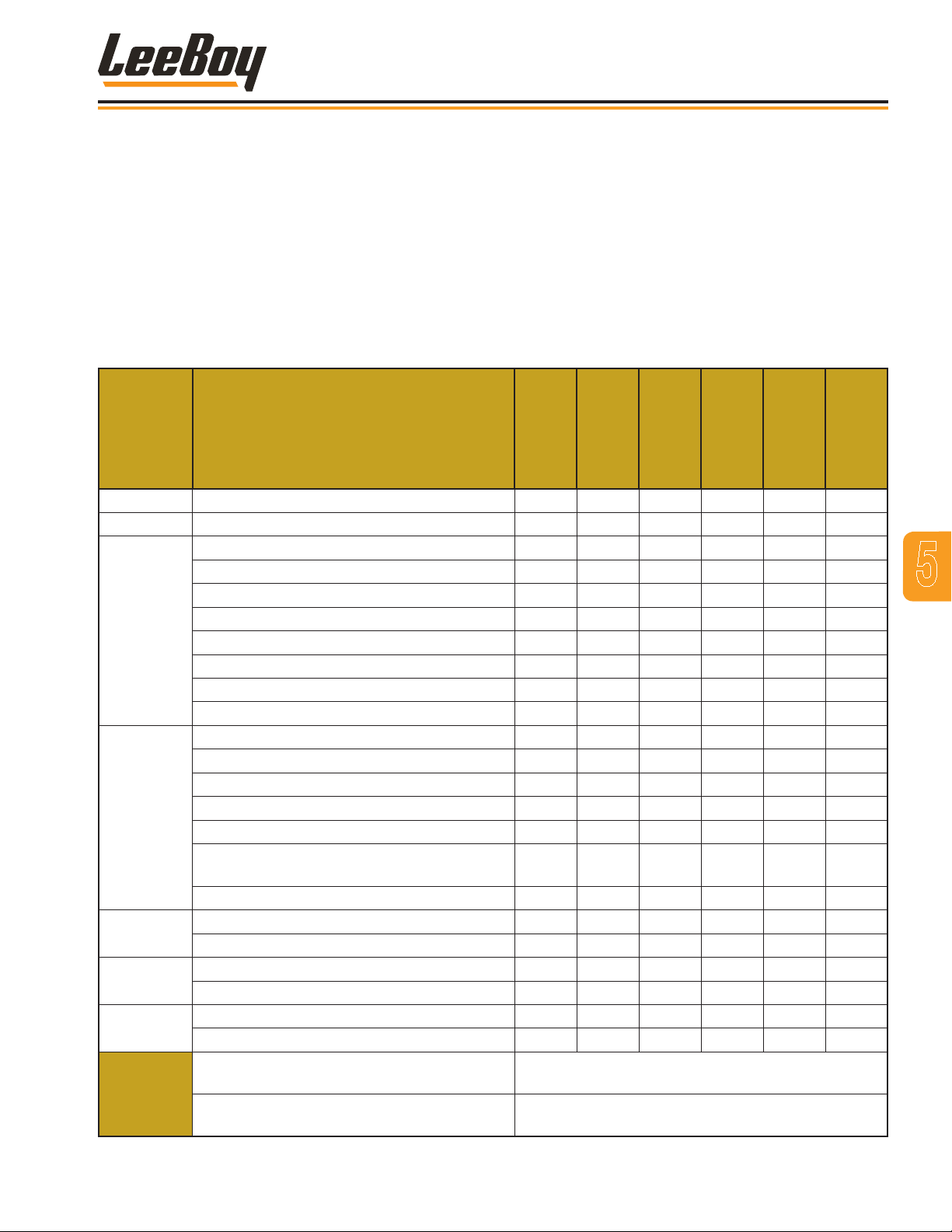
Maintenance
GENERAL INFORMATION
This section gives the necessary procedures for routine
and general maintenance on the LeeBoy 3000C Force
Feed Loader. Keep the loader clean and follow all
maintenance schedules and procedures to maintain the
machine in top operating condition.
Maintenance must be a planned program that
includes periodic machine inspection and lubrication
procedures. The operator should inspect the machine
Table 1-1.Periodic Maintenance Schedule
SYSTEM ITEM
Loader Lubricate machine. X
Conveyor Check conveyor belt alignment. X
Check 2-Speed gear box oil level. X
Check planetary hub gear oil level. X
Inspect hydraulic hoses. X
Hydraulic
Engine
Electrical
Fuel
Cooling
DEF
Replace hydraulic oil charge lter cartridge. X
Check hydraulic oil level. X
Change hydraulic oil. X
Check pump drive gear oil. X
Check differential oil level. X
Inspect belts, replace if needed. X
Inspect air intake hoses and clamps. X
Inspect alternator and connections. X
Replace engine oil and oil lter cartridge. X
Check oil level - change at initial 50 hours. X
Check air cleaner indicator. Clean and
replace if indicator is red.
Change crankcase ventilation lter. X
Inspect battery cables and connections. X
Service battery. X
Replace fuel lter cartridge. X
Inspect fuel system hoses and clamps. X
Check coolant level. Fill if needed. X
Inspect coolant hoses and clamps. X
Diesel Exhaust Fluid (DEF) Tank Filter
DEF Supply Module Filter
daily. Worn or damaged parts should be replaced or
repaired promptly to prevent damage to other areas of
the machine. Daily inspections should include checking
for loose bolts, uid leaks, worn or damaged hoses, and
debris or dirt accumulations to prevent potential service
or safety problems.
The maintenance program should be done based on the
machine “Operating Hours” recorded on the hour meter
or by following the Periodic Schedule shown below.
Every
10 Hours
X
Inspect every 2000 hours (or 2 years). Clean or
replace if needed.
Inspect every 4500 hours (or 3 years). Clean or
replace if needed.
Every
50 Hours
Every
100 Hours
Every
250 Hours
Every
500 Hours
Every
1000 Hours
5
3000C Force Feed Loader 5-3
Page 58
Maintenance
MAINTENANCE SCHEDULE
Before performing any maintenance procedures on the
LeeBoy 3000C Force Feed Loader, read the following
safety information and review Safety in Section 2.
Tool Hazard! ALWAYS use tools
appropriate for the task. Be sure to use the correct
sized tool for loosening or tightening parts.
Follow all maintenance schedules and procedures
to maintain the machine in top operating order. The
maintenance schedule begins with 10-hour, or daily,
maintenance intervals and continues through the 1000hour, or annual, maintenance schedule intervals.
NOTE: When performing any routine maintenance,
always include previous routine
maintenance procedures to the higher
hourly schedule.
Preventive maintenance on the loader will provide
years of trouble-free operation. Adjustments can be
performed in the eld with ordinary tools.
Engine preventive maintenance, (other than oil, air
and fuel lter changes), can be found in the Engine
Operator’s Manual.
Anytime the loader has been repainted or the decals
removed, damaged or illegible, replace immediately for
safe operation.
Changing oil and cleaning the loader
should only be done in a designated area where the
the oil and chemicals can be contained. These byproducts should be discarded in accordance with
environmental regulations.
Failure to observe the operating
precautions and warning instructions provided in
this manual can cause serious injury or death. Only
authorized personnel who are properly trained
should operate the LeeBoy Model 3000C Force
Feed Loader.
Do not operate a machine that is
in need of repair. Put an information tag on the
instrument panel that says “DO NOT OPERATE”
and remove key from the ignition switch. Repair all
damage promptly as even minor damage can result
in major system failures.
NOTE: If the machine is operated more than 10
hours per day, follow the “Hour” schedules.
If the machine is operated less than 10 hours
per day, follow the “Periodic” schedules.
10-Hour or Daily Routine Maintenance
1. Check engine oil. Add more if needed. (Page 5-8)
2. Check coolant level. Add more if needed. (Page
5-7)
3. Check air lter indicator. Clean or replace if
indicator is red. (Page 5-10)
4. Check hydraulic oil level. Add more if needed.
(Page 5-14)
5. Check battery cables and connectors. (Page 5-17)
6. Check conveyor belt alignment. (Page 4-12)
7. Check hydraulic hoses for leaks and wear.
50-Hour Routine Maintenance
The LeeBoy 3000C Force
Feed Loader hydraulic system requires clean,
contaminant-free oil. Be careful working with the
hydraulic system to ensure it is completely clean.
1. Perform previous maintenance procedures.
2. Lubricate machine. (Page 5-6)
3. Inspect fuel system and clamps. (Page 5-13)
4. Perform any other engine preventative maintenance
as described in the Engine Operator’s Manual.
100-Hour or Monthly Routine Maintenance
1. Perform previous maintenance procedures.
2. Inspect air intake hoses and clamps.
3. Check for loose, missing, damaged or corroded
parts. Repair or replace as necessary.
4. Check pump drive gear oil. Add more if needed.
(Page 5-16)
5. Change engine oil and oil lter. (Page 5-9)
6. Perform any other engine preventative maintenance
as described in the Engine Operator’s Manual.
7. Check tire pressure. (Page 5-7)
3000C Force Feed Loader5-4
Page 59
Maintenance
250-Hour or Quarterly Routine Maintenance
1. Perform previous maintenance procedures.
2. Replace fuel lters. (Page 5-13)
3. Replace hydraulic oil lter. (Page 5-16)
4. Inspect engine drive belt. Replace if needed. (Page
5-10)
5. Check for damaged, loose, or missing decals.
Replace decals as required. (Page 1-8)
6. Check differential oil level. Add more if needed.
(Page 5-16)
7. Check planetary hub uid level. Add more if needed.
(Page 5-17)
8. Service battery. (Page 5-17)
9. Inspect coolant hoses and clamps. (Page 5-7)
10. Perform any other engine preventative maintenance
as described in the Engine Operator’s Manual.
500-Hour or Semi-Annual Routine Maintenance
1000-Hour or Annual Routine Maintenance
1. Drain and ush the hydraulic tank. A drain plug
is located on the bottom of the tank for this
purpose. Clean the strainer screens in the tank.
The recommended hydraulic oil is Citgo All-Temp.
(Page 5-15)
2. Perform the 1,000-hour preventative maintenance
as described in the Engine Operator’s Manual.
3. Check for damaged, loose, or missing decals.
Replace decals immediately for operator safety.
(Page 1-8)
4. Perform any other engine preventative maintenance
as described in the Engine Operator’s Manual.
2000-Hour or Annual Routine Maintenance
1. Inspect the Diesel Exhuast Fluid (DEF) lter. Clean
or replace if needed. (Page 5-12)
2. Perform any other engine preventative maintenance
as described in the Engine Operator’s Manual.
5
1. Perform previous maintenance procedures.
1. All bearings are sealed and have grease ttings.
These should be greased with multipurpose grease
using a grease gun. (Page 5-6)
2. Replace air lter. (Page 5-10)
3. Perform any other engine preventative maintenance
as described in the Engine Operator’s Manual.
3000-Hour or Annual Routine Maintenance
1. Inspect the DEF Supply Module Filter. Clean or
replace if needed. (Page 5-12)
2. Perform any other engine preventative maintenance
as described in the Engine Operator’s Manual.
3000C Force Feed Loader 5-5
Page 60
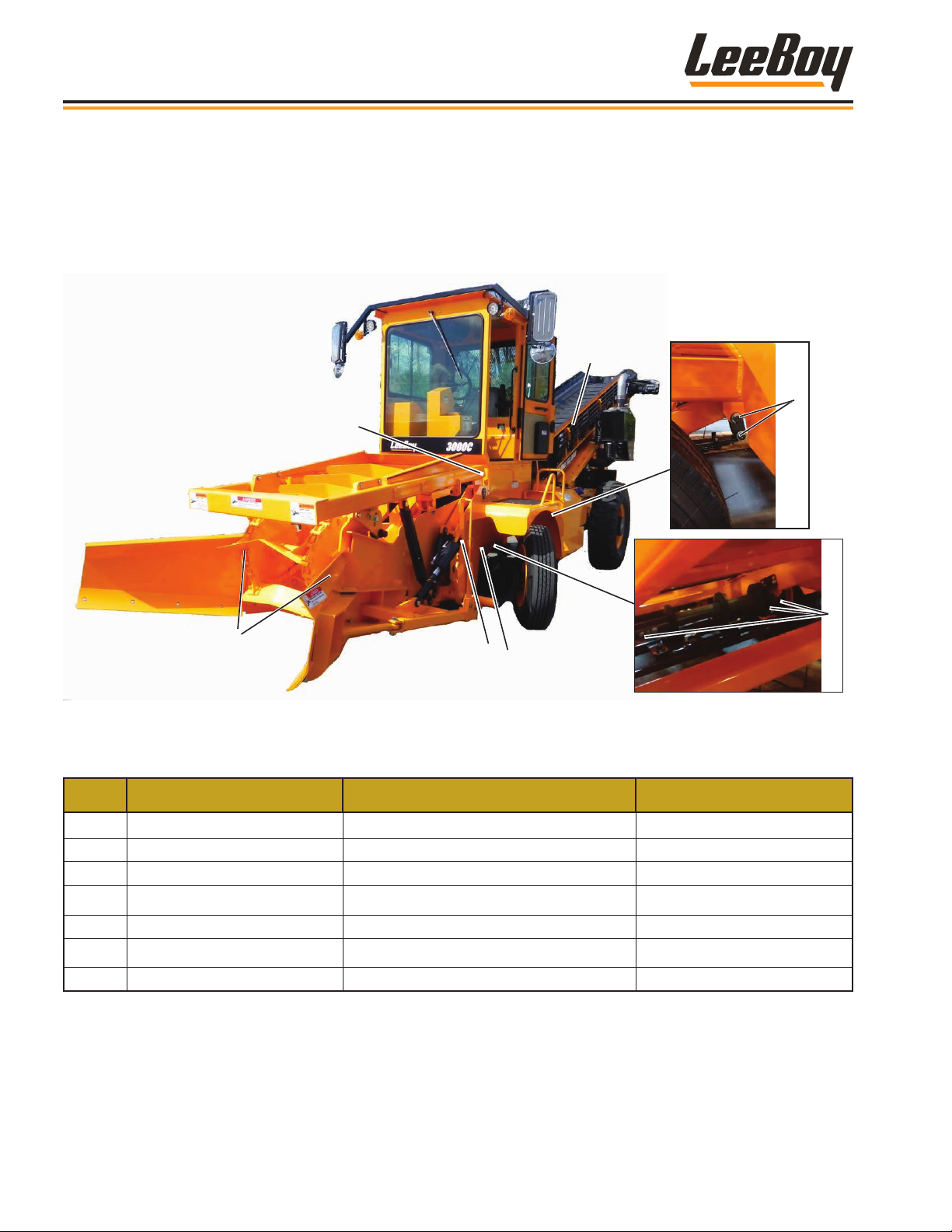
Maintenance
LUBRICATION POINTS
Proper lubrication is necessary to maintain the machine at top efciency. Refer to the lubrication information in Table
5-1. Lubrication points are shown below:
7
6
4
2
3
1
Table 1-3. Lubrication Points Schedule
No. ITEM TYPE OF LUBRICANT INTERVAL
1 King Pin Bearings Shell Avania EP Grease 50 Hours
2 Feeder Bearings Shell Avania EP Grease 50 Hours
3 Leaf Spring Pin Shell Avania EP Grease 50 Hours
4 Feeder Pins Shell Avania EP Grease 50 Hours
5 Tie Rod Ends Shell Avania EP Grease 50 Hours
6 Spring Hangers Shell Avania EP Grease 50 Hours
7 Rear Head Pulley Bearings Shell Avania EP Grease 50 Hours
5
3000C Force Feed Loader5-6
Page 61
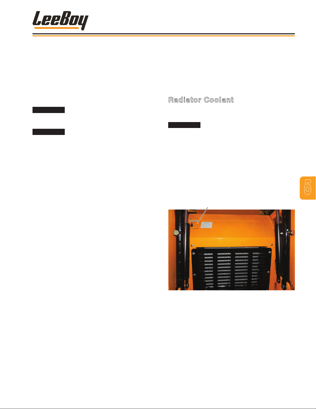
Maintenance
TIRE REPLACEMENT
The tires should be maintained at the proper tire
pressure and checked monthly. Front tires should
be maintained at 90 PSI while rear tires should be
maintained at 45 PSI.
If a tire appears to be low when performing the daily
check of the machine, measure the pressure to be sure
of proper ination.
The rim and tire assemblies for the
wheels are very heavy and must be supported when
lug nuts are removed.
Engine must be turned off and the
wheels blocked to prevent motion when servicing the
machine.
1. Turn off engine and block the wheels to prevent
movement while working on the machine.
2. Loosen lugnuts.
3. Release any air that remains in the tire.
4. Use a jack or hoist to lift the side of the machine.
5. Place supports under the machine.
6. Attach a sling or other support to the tire.
COOLING SYSTEM
The following information covers general maintenance
procedures that are most often required. For specic
engine maintenance information, see the Engine
Operator’s Manual.
Radiator Coolant
The radiator surge tank ll cap is located behind a small
access door marked RADIATOR. (Figure 5-1)
DO NOT remove the radiator surge
tank cap while the engine is still hot. The radiator is
under pressure and the hot water can cause serious
injury.
To check the radiator or add coolant:
1. Open the access door to access the radiator surge
tank cap. (Figure 5-1)
2. Remove the cap to check ONLY WHEN UNIT IS
COOL. Coolant level should be visible.
3. If coolant level is low, add coolant. DO NOT overll.
Radiator Surge Fill Cap
5
7. Remove the eight (8) lugnuts from the wheel.
8. Release any air that remains in the tire.
9. Using standard tire removal tools, remove the tire
from the wheel.
10. Install new tire on the wheel.
11. Add air. Measure PSI using tire pressure gauge.
Inate tire to proper PSI (90 PSI for front tires; 45
PSI for rear tires).
12. Align the mounting holes with the studs on the hub.
13. Reinstall the eight lug nuts.
14. Torque the lug nuts in a diagonal pattern to 300 ft-lb
(407 N.m).
15. Remove supports and lower jack.
Figure 4-1. Engine Radiator Surge Tank Fill Cap
3000C Force Feed Loader 5-7
Page 62
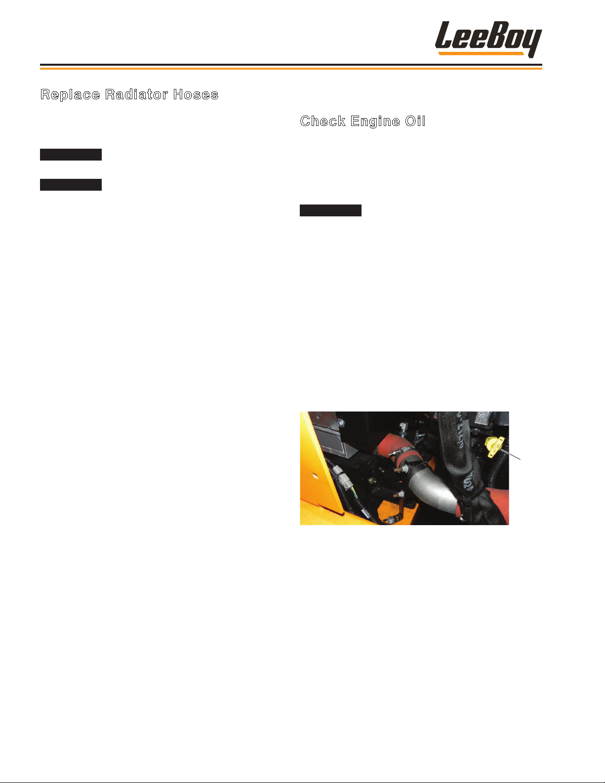
Oil
Dipstick
Maintenance
Replace Radiator Hoses
Radiator hoses should be replaced if worn or frayed.
Replacement parts are listed in Section 7, Illustrated
Parts List (IPL).
This procedure should only be
performed when the equipment is not operating.
DO NOT remove the radiator cap while
the engine is still hot. The radiator is under pressure.
Removing the cap could cause serious injury.
1. Turn off ignition, remove key, and allow the engine to
cool down before proceeding:
2. Remove the radiator surge tank cap.
3. Drain radiator into a suitable container (5.5 gallons
or 20.8 liters).
4. To remove upper hose, loosen the two hose clamps
and disconnect. If clamps are not damaged, retain
for installation.
5. To remove lower hose, loosen the two hose clamps
and disconnect. If clamps are not damaged, retain
for installation.
6. Install new hoses in reverse order of procedures
above.
ENGINE MAINTENANCE
Check Engine Oil
The engine lubrication oil must be kept at a level above
the ADD mark, but not above the FULL mark, on the
engine lubrication oil dipstick.
To accurately check the engine lubrication oil level, park
the machine on a level surface and stop the engine.
ALWAYS stop the engine before
checking the engine lubrication oil level as hot oil
can be thrown, causing serious injury.
Wait ve minutes after engine
shutdown before removing the dipstick from the
engine and checking the oil level to assure accuracy.
This also prevents lling the engine with too much
lubrication oil. Engine oil should be warm when
checked.
1. Lift engine cover located on the right side (rear) of
machine to access the oil dipstick. (Figure 5-2)
2. Clean around the engine lubrication oil dipstick
before removing it from the engine.
3. Removing dipstick from the engine, wipe with a
clean cloth, then reinsert.
Figure 4-2. Engine Oil Dipstick Location
4. Pull dipstick out of the engine and check that oil
level is near the full mark on the dipstick.
5. To add oil, remove the ll cap located next to the
dipstick. Twist to remove cap and twist to install (use
15W40 motor oil). (Figure 5-3)
3000C Force Feed Loader5-8
Page 63
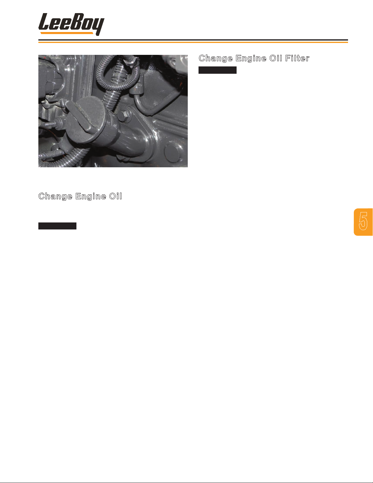
Figure 4-3. Engine Oil Fill Cap
Change Engine Oil
The engine oil must be changed according to the
intervals given in the Engine Operator’s Manual.
Maintenance
Change Engine Oil Filter
DO NOT change the engine lubrication
oil while the engine and lubrication oil are hot.
Change when warm only. Hot oil can cause serious
injury.
DO NOT change the engine lubrication
oil lter with the engine running. Serious engine
damage or failure can occur.
After the engine lubrication oil has been changed,
proceed as follows:
1. Wipe the area around the engine lubrication oil lter
element and its mounting base with a clean cloth.
2. Place a container under the lter element.
3. Use a lter removal wrench to loosen and remove
the lter element by turning it in a counterclockwise
direction. Drain and discard the removed lter
element.
NOTE: Be sure the used rubber gasket is removed
and discarded with the lter element.
DO NOT change the engine lubrication
oil when the engine and lubrication oil are hot. Hot
oil can cause serious injury.
DO NOT change the engine lubrication
oil while the engine is running as serious damage or
engine failure can occur.
The engine lubrication oil lter must be
changed when the engine lubrication oil is changed.
While the engine is warm, proceed as follows:
1. Clean the area around the engine lubrication oil
drain.
2. Place a container that has sufcient capacity to hold
the drained oil directly under the engine lubrication
oil drain plug.
3. Carefully remove the engine lubrication oil drain
plug.
4. Clean, install and carefully tighten the lubrication oil
drain plug.
DO NOT overtighten the drain plug.
5. Fill the engine with 15 quarts (14.2 liters) of oil.
NOTE: Comply with environmental laws by
properly discarding used oil.
4. Wipe the inside area of the lubrication oil lter head
using a clean, lint-free cloth.
5. Put clean engine lubrication oil on the rubber gasket
area of the new lter element. Fill the new lter
element with the new oil.
6. Install the new lter element onto the lter head.
Carefully tighten the lter element (by hand only).
NOTE: Tighten the lter element as directed by the
lter manufacturer.
5
6. Reinsert the engine lubrication oil dipstick.
DO NOT start the engine before
changing the oil lter.
3000C Force Feed Loader 5-9
Page 64
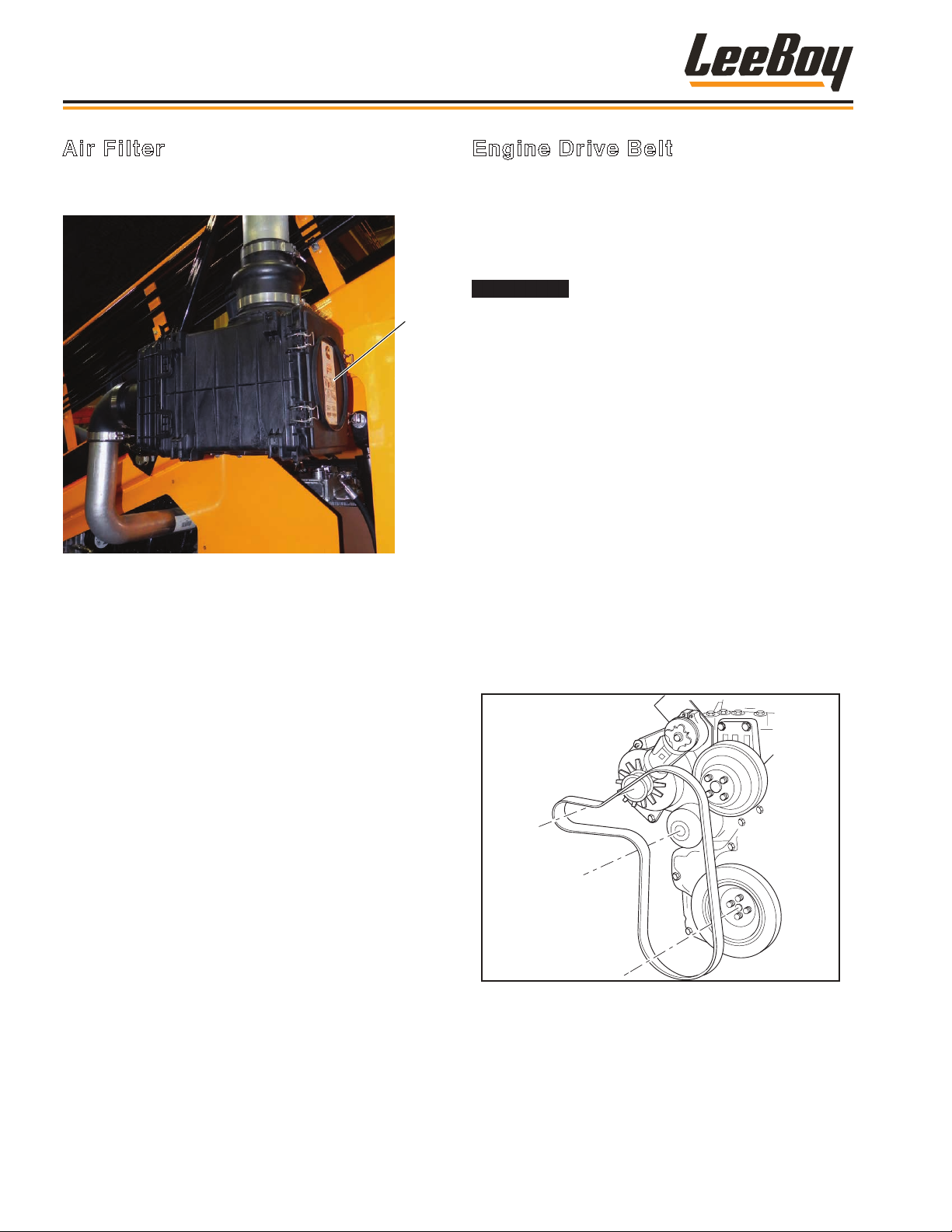
Maintenance
Air Filter
The air lter indicator is located on the intake of the air
lter. (Figure 5-4)
Air
Filter
Box
Figure 4-4. Air Filter Box
As the air lter becomes more clogged, the air pressure
increases, causing the indicator to illuminate. When
this occurs, the air lter must be cleaned or replaced as
follows:
1. Open clamps securing the cover on the lter
housing, then remove the cover.
Engine Drive Belt
The engine drive belt should be replaced whenever the
belt appears frayed or cracked. This belt drives the
alternator and the cooling fan. Tension on the belt is
maintained by a spring-loaded tensioner.
To replace the belt proceed as follows:
Engine must be turned off and the
wheels blocked to prevent motion when servicing the
machine.
NOTE: The spring-loaded belt tensioner must be
pivoted away from the drive belt. Pivoting
in the wrong direction can damage the
tensioner.
To replace the belt :
1. Turn off engine and block the wheels to prevent
movement while working on the machine.
2. Using a 3/8-inch square drive, lift the tensioner
to relieve pressure on the belt. Remove the belt.
(Figure 5-5)
3. Using a 3/8-inch square drive, lift the tensioner and
hold.
4. Install the new drive belt.
5. Release the tensioner, ensuring it is properly
pressing against the belt.
2. Remove the lter cartridge.
3. Replace with the new lter cartridge.
4. Reinstall cover and secure with the clamps.
5. Reset the lter indicator by pressing button on top of
the indicator.
Figure 4-5. Drive Belt
3000C Force Feed Loader5-10
Page 65
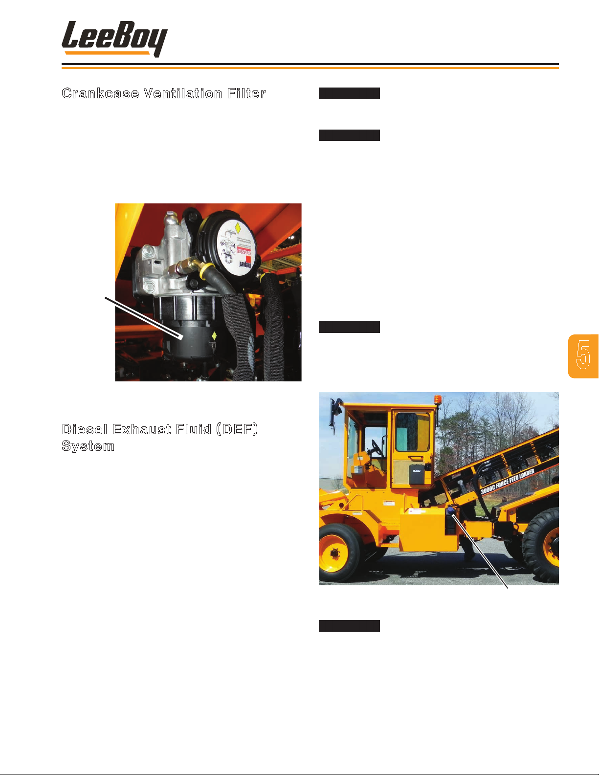
Maintenance
Crankcase Ventilation Filter
The crankcase ventilation lter should be changed every
1000 hours (or anually). (Figure 5-6)
1. Engine should be off to change this lter.
2. Unscrew lter housing.
3. Remove old lter.
4. Insert new lter and reinstall lter housing.
Crankcase
Filter
Figure 4-6. Crankcase Ventilation Filter
DO NOT pressurewash or steamclean
this unit to avoid damage the components. Use
compressed air to remove any loose debris.
DEF contains urea, therefore, wear
safety glasses when performing these procedures.
DO NOT get the substance in your eyes. In case of
contact, immediately ush eyes for a minimum of 15
minutes.
Before servicing any component in the DEF system,
allow the DEF system to purge. You will hear the
pumping noise as the system completes the purge cycle
automatically after shutting down the engine.
1. Shift transmission into neutral.
2. Apply the parking brake.
3. Shut off the engine. Wait at least ve minutes after
shutting down the engine for the aftertreatment DEF
dosing unit to complete its automatic purge cycle.
DO NOT disconnect battery until the
purge cycle has completed to prevent damage to the
unit.
4. Place battery master switch in the OFF position.
(Page 5-16)
5
Diesel Exhaust Fluid (DEF) System
The DEF system is an efcient, effective means of
ltering dirt and other contaminates for optimum
machine performance and reducing air pollution from
exhaust emissions. A sensor on the DEF tank header
monitors the level, temperature and quality of DEF in
the tank. The header is mounted on top of the DEF
tank and provides ltered DEF supply from the tank to
the aftertreatment DEF dosing unit. Both the DEF tank
header and dosing unit have serviceable lters that
require cleaning or replacement. Fill the DEF tank with
DEF uid at any gas station and be sure to keep the tank
full. (Figure 5-7)
The DEF system will automatically purge the uid
from the system after shutting down the machine and
requires no intervention from the operator.
NOTE: Check the ttings around the DEF tank
header for leaks or any signs of damage
regularly. DEF leaks will leave a white
deposit around the ttings.
DEF Tank
Figure 4-7. DEF Tank
It’s important to service the DEF
system in a clean, dust-free environment to prevent
contamination in the DEF tank that can damage the
aftertreatment DEF dosing unit.
3000C Force Feed Loader 5-11
Page 66
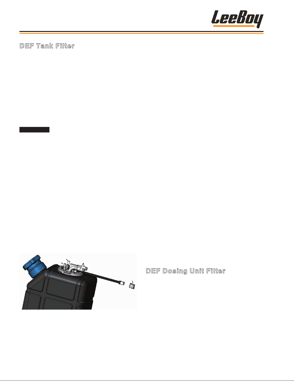
Maintenance
DEF Tank Filter
The DEF tank lter should be cleaned or replaced every
2000 hours, or every two years, whichever is rst. The
lter is the rst point of contact with foreign elements.
To clean or replace the DEF tank lter, remove the DEF
header tank assembly using the following procedures.
The DEF lines are connected using quick-release
ttings and must be disconnected in the order
described below. (Figure 5-8)
NOTE: It is imperative that you disconnect the
plumbing from the header in the exact order
described below to prevent accidental DEF
contamination of the electrical connector.
Wear eye protection, gloves and
appropriate protective clothing to avoid injury. The
coolant lines connect to the aftertreatment dosing
unit are hot and under pressure. DO NOT disconnect
while the engine is running or before the system has
purged and cooled down after shutting down the
engine. Disconnecting the coolant lines before the
system cools down may cause coolant to spray and
burn skin on contact.
1. Complete Steps 1 - 4 on Page 5-11 to prepare
machine for DEF system maintenance.
2. Place a container under the DEF tank as a small
amount of DEF may drain from the coolant lines
when disconnected. (Dispose of the uid in
accordance with environmental regulations.) DO
NOT ush the coolant.
3. Use a clean, damp cloth to wipe the unit to reduce
the risk of contamination entering the DEF tank.
Wipe away any spilled DEF while servicing the DEF
tank lter.
2
1
3
4. Disconnect the coolant connectors and cap the
lines to prevent contamination or DEF leakage. (You
can also use a pair of coolant hose pinch-off pliers
to clamp the lines. Make sure the tank coolant
hose material is exible enough.) DO NOT drain the
cooling system. DO NOT spill any coolant into the
DEF tank.
5. Disconnect the DEF connector.
6. Disconnect the suction DEF connector.
7. Disconnect the backow DEF connector.
8. Disconnect the electrical connector by pressing the
top of the tting.
9. Remove the header from the tank by removing the
six bolts on the metal ring separating the header
from the tank. Slowly and carefully lift the header
out of the DEF tank, exposing the lter unit, to avoid
damaging the lter or other components.
10. Remove the clip, pull the lter cartridge out and
inspect for cracks, damage and contamination
or debris. Clean the lter and reinsert, unless
replacing the lter at service interval or if debris or
damage is evident:
• Discard the lter element and O-ring in
accordance with environmental regulations and
replace with a new lter element.
• Also inspect the aftertreatment DEF dosing unit
lter after replacing the tank lter. (Page 5-13)
11. Lubricate the O-rings with clean DEF uid and install
the new lter element (O-ring side facing outward) in
its seated notch loaction.
12. Reinstall the lter cartridge into the DEF tank.
13. Reinstall the tank lter header in reverse order
Figure 4-8. DEF Tank Header Assembly
1 - Suction DEF Connector
2 - DEF Connector
3 - Coolant Connectors
4 - Electrical Connector
DEF Dosing Unit Filter
4
The DEF dosing unit lter prevents foreign objects that
may be suspended in the DEF from entering the dosing
system, which draws DEF from the tank, pressurizes
it, and delivers the DEF through a dosing valve. Any
unused DEF is then routed back to the tank. The DEF
dosing unit lter should be replaced every 4500 hours
or three years, whichever comes rst. It is located on
the left inside the rear access panel on the driver’s side.
Follow these procedures to replace the dosing unit lter:
1. Follow Steps 1 - 4 on Page 5-11 to prepare machine
for DEF system maintenance.
3000C Force Feed Loader5-12
Page 67
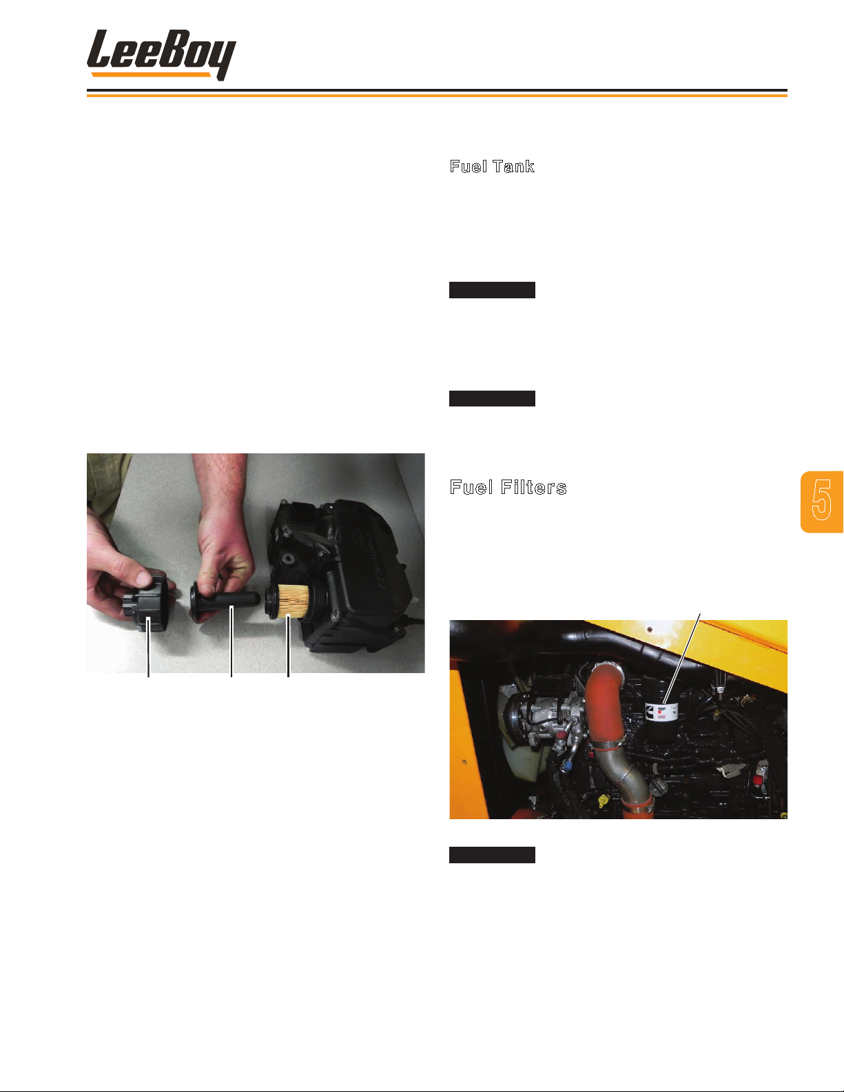
Fuel Filter
Maintenance
2. Place a container under the DEF dosing unit as a
small amount of DEF may drain from the lines when
disconnected. (Dispose of the uid in accordance
with environmental regulations.)
3. Use a clean, damp cloth to wipe the unit to reduce
the risk of contamination entering the DEF system.
Debris can cause permanent damage and
premature failure in the DEF dosing unit.
4. Unscrew the DEF lter cap and remove the
equalizing element and lter element. (Figure 5-9)
5. Discard both the lter element and equalizing
element in accordance with environmental
regulations.
6. Reinstall the new lter and equalizing element.
7. Reinstall and tighten the cap.
NOTE: Lubrication on the DEF lter O-ring is not
required.
FUEL SYSTEM
Fuel Tank
The fuel level is indicated on the digital display
component on the dashboard.
NOTE: Fill the tank to FULL before storing the
loader overnight to reduce moisture accumulation
from condensation in the tank.
The operator should NEVER be on
or near the loader while fuel is being added. NO
SMOKING while lling the fuel tank as all fuels for
internal combustion engines are ammable. Fill the
fuel tank only in a designated area where there is
good ventilation and a re extinguisher available.
NEVER ll the tank, check fuel level
or check for fuel leaks near an open ame or near
equipment that can create sparks.
Fuel Filters
The fuel lter elements must be replaced as directed
in the Engine Operator’s Manual. The fuel lter is
located on top of the engine (Figure 5-10) and the fuel
separator is located at the right side of the frame rail
(Figure 5-11).
5
1 2 3
Figure 4-9. DEF Tank Filter
1 - Filter Cap
2 - Filter Equalizing Element
3 - Filter Element
Figure 4-10. Fuel Filter Box
Diesel fuel is very ammable. Use
3000C Force Feed Loader 5-13
extra caution and DO NOT spill fuel. DO NOT change
the fuel lter while the loader is running. DO NOT
change the fuel lter in an area near an open ame.
DO NOT smoke while changing the fuel lter.
Page 68
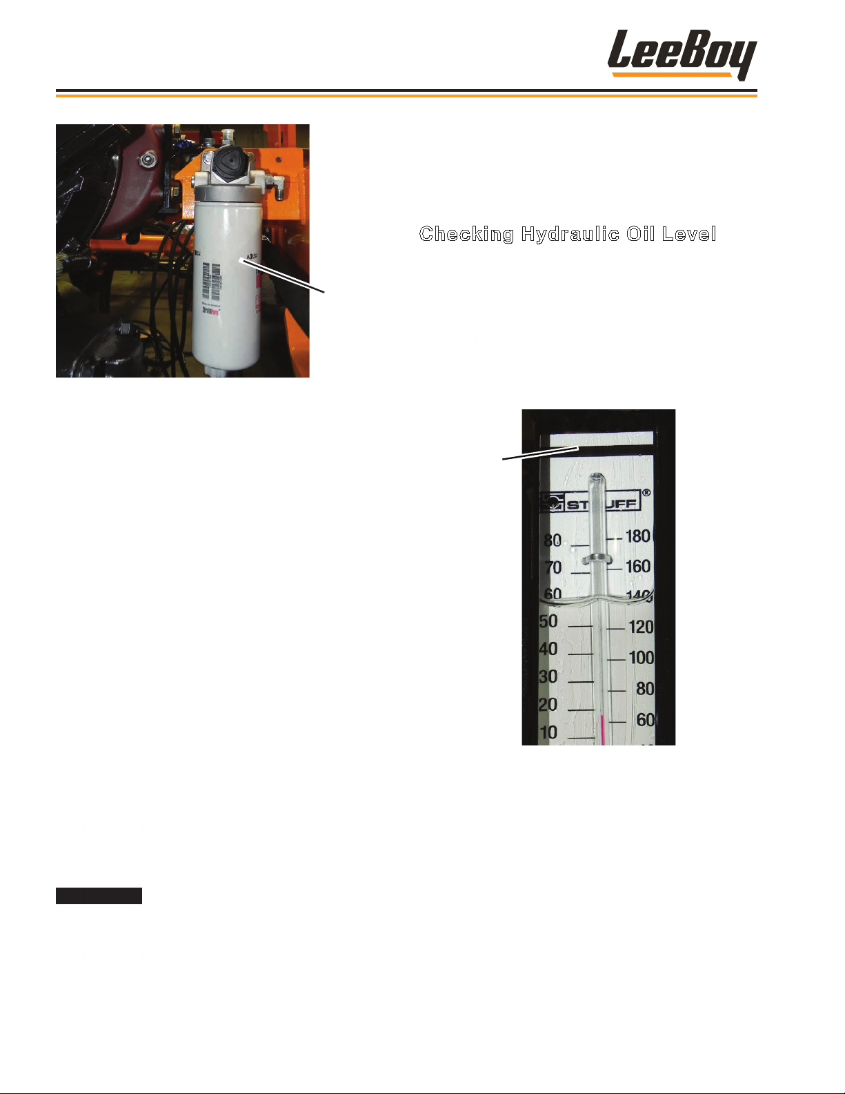
Hydraulic Oil
Level Line
Maintenance
Fuel
Separator
Figure 4-11. Fuel Water Separator Filter
Replace the fuel and water separator lters using the
following general procedures:
1. Stop the engine.
HYDRAULIC SYSTEM
The hydraulic motors and the hydraulic cylinders use
the same hydraulic oil reservoir and hydraulic oil supply.
Checking Hydraulic Oil Level
1. Make sure all cylinders are retracted, so that oil
ows to tank, ensuring an accurate reading.
2. Wait 10 minutes after engine has been shut down
before checking hydraulic oil.
Oil level is determined by sight gauge.
(Figure 5-12) Hydraulic oil should be added if the
oil level falls below the ll line. Never ll above the
black ll line.
2. Put a container under fuel lters before removing
NOTE: Consider the environment when discarding
3. Wipe the area around the fuel lter elements and
4. Use a lter removal wrench to loosen and remove
5. Wipe the inside area of the lter heads with a clean,
6. Put clean fuel onto the element rubber gaskets.
7. Install the new fuel lter elements onto the lter
elements onto the lter heads.
8. Start the engine and check for ANY fuel leaks.
the lter elements.
used lters and do so according to safe and
lawful practices.
element mounting heads using a clean, lint-free
cloth.
fuel lter elements by turning in a counterclockwise
direction. Drain and discard the removed elements.
lint-free cloth. Fill the new fuel lter elements
completely with clean fuel.
heads. Carefully tighten the elements (by hand
only).
DO NOT overtighten the fuel lter
Figure 4-12. Hydraulic Gauge
3. If level is low, remove hydraulic oil ller cap to add
hydraulic oil to the tank.
4. Fill tank to the black ll line on sight gauge.
5. Screw the hydraulic oil ller cap back onto the
hydraulic tank.
STOP the engine immediately if any
fuel leakage is noted. DO NOT start the engine until
the leakage problem is corrected.
NEVER loosen a fuel injector line as
contents are under high pressure. DO NOT try to
bleed air by loosening injector lines.
3000C Force Feed Loader5-14
Page 69
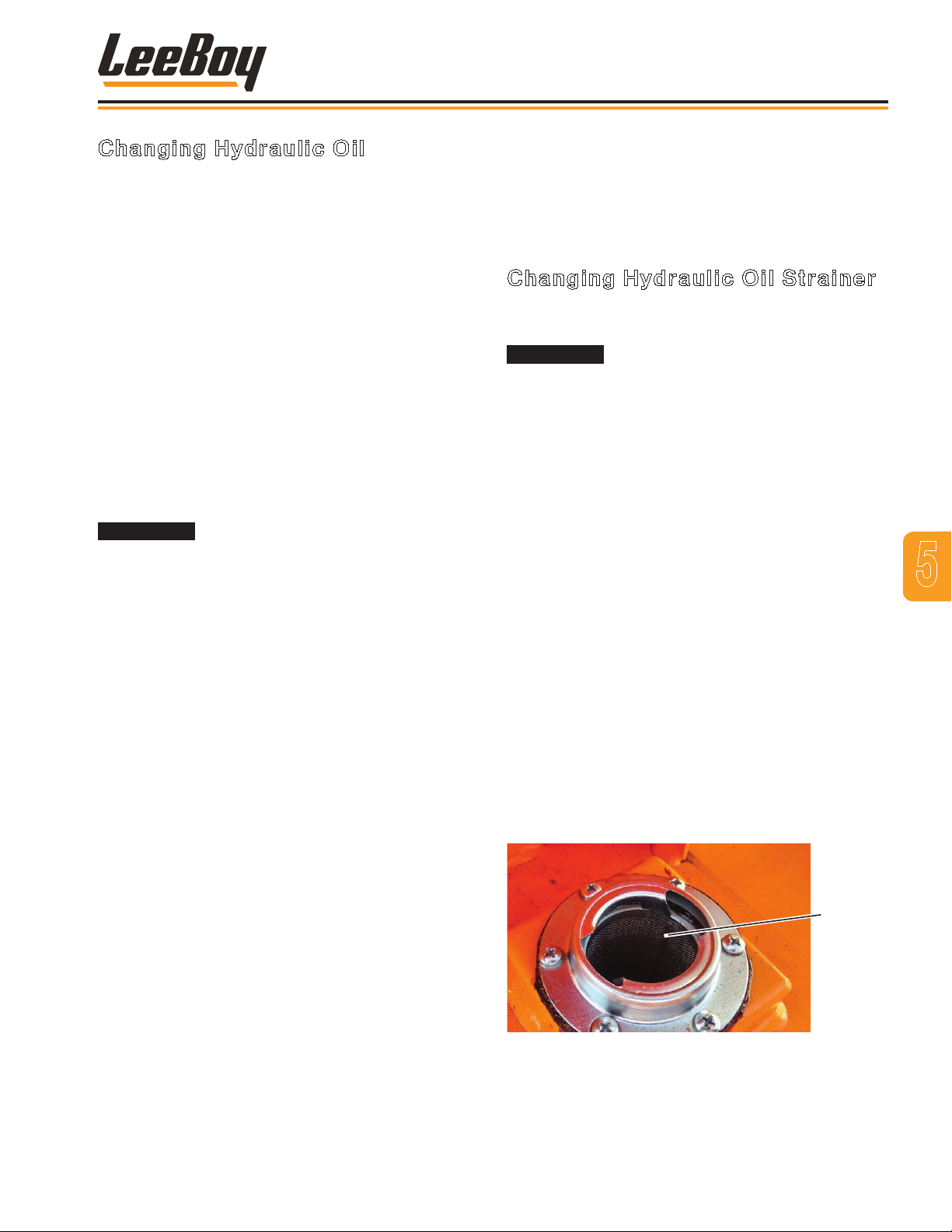
Maintenance
Changing Hydraulic Oil
Changing the hydraulic oil removes the accumulation
of dirt, water and mechanical wear particles from the
hydraulic oil reservoir and system. The chemical
structure of hydraulic oil changes after continuous
use, therefore, new oil is important to ensure correct
operation of the hydraulic system.
Hydraulic oil that has oxidized or
contains contamination can shorten the expected
service life of the components in the hydraulic
system.
Use the following procedures to change the hydraulic
oil:
1. Stop the engine. Allow the hydraulic oil to cool
until it is at a warm temperature. Slowly loosen and
remove the hydraulic oil reservoir ller cap (Figure
5-13). Put a clean, lint-free cloth over the reservoir
ll tube opening and secure in place with tape.
DO NOT drain the hydraulic oil from
the reservoir when it is HOT. Hot hydraulic oil can
cause serious injury. Drain at a warm temperature
only.
2. Carefully remove the plug from the hydraulic
tank. Use a drain collection container of sufcient
capacity to collect the hydraulic oil underneath.
Allow all of the hydraulic oil to drain into the
container.
DO NOT ll the hydraulic oil reservoir
with new hydraulic oil until the suction strainer has
been serviced.
3. Check the hydraulic suction strainer in bottom of the
hydraulic oil tank. Clean if necessary.
4. Install the hydraulic oil reservoir drain plug and
tighten securely.
8. Replace the hydraulic oil ller cap onto the reservoir
ller neck and tighten securely.
9. Start the engine.
10. Check the hydraulic system for any leaks.
Changing Hydraulic Oil Strainer
The oil strainer is mounted in the hydraulic oil ller
opening under the ller cap. (Figure 5-13)
DO NOT remove the hydraulic ller
cap from the reservoir when it is hot as this can
cause serious injury. Allow hydraulic oil to cool down
to a warm temperature.
To change the hydraulic oil strainer:
1. Remove the hydraulic oil ller cap.
2. Remove the six (6) screws securing the strainer,
then remove the strainer and gasket.
3. Install a new gasket, aligning the six screw holes in
the gasket with the mounting holes on the reservoir.
4. Install the new strainer, aligning the holes in the
strainer with the mounting holes of the gasket and
secure the strainer with the six screws.
5. Fill the hydraulic oil reservoir with (recommend
Citgo All Weather/All Temperature Multiviscosity
hydraulic oil).
DO NOT overll the hydraulic oil
reservoir with oil.
6. Check the oil level in the hydraulic oil reservoir. Add
oil if needed.
7. Reinstall the hydraulic oil ller cap and tighten
securely.
5
5. Carefully remove the cloth from the hydraulic oil
reservoir ll tube opening.
6. Rell the hydraulic oil reservoir (recommend Citgo
All Weather/All Temperature Multiviscosity hydraulic
oil).
DO NOT overll the hydraulic oil
reservoir with oil.
Never let tank run dry. Pump damage
will occur.
7. Check the oil level in the hydraulic oil reservoir,
again. Add oil if needed.
3000C Force Feed Loader 5-15
Figure 4-13. Hydraulic Oil Strainer
Hydraulic
Oil Strainer
Page 70
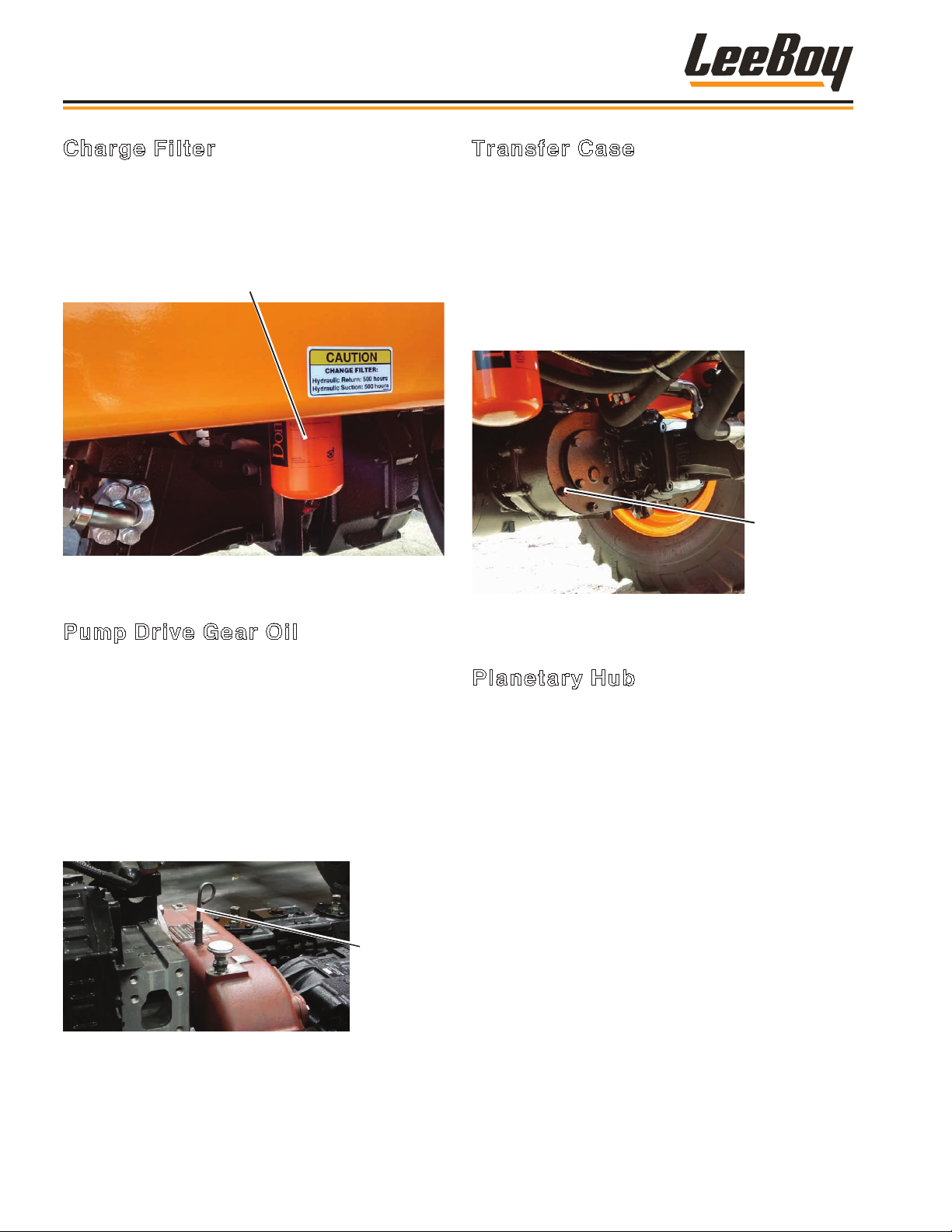
Transfer Case
Gear Oil Plug
Maintenance
Charge Filter
There are two charge lters, one on each side of the
machine. These lters should be changed when the
hydraulic uid is changed. Simply unscrew the lters,
dispose of properly, and reinsert new lters. (Figure
5-14)
Charge Filter
Figure 4-14. Charge Filters
Transfer Case
The transfer case is located on front the rear axle.
(Figure 5-16)
To check the transfer case gear oil level:
1. Shut down machine and apply park brake.
2. Unscrew the transfer case gear oil plug.
3. Oil should be level with bottom of plug hole.
4. Fill if needed.
Pump Drive Gear Oil
It is important to check the pump drive gear oil level and
ll if needed. (Figure 5-15)
To check the pump drive gear oil level:
1. Shut down the machine and let the engine cool.
2. Unscrew the dipstick (red cap).
3. The gear oil level should reach the top of the knurl
section on the dipstick.
4. Fill if needed and reinsert dipstick.
Pump Drive
Gear Oil
Dipstick
Figure 4-15. Pump Drive Gear Oil Dipstick
Figure 4-16. Transfer Case Gear Oil Plug
Planetary Hub
The planetary hub is mounted on each side of the rear
axle. (Figure 5-17)
You will need an assistant to properly check the the
gear oil level:
1. With assistance from a ground guide, the operator
should slowly drive the machine forward until the
planetary hub plug is at the 3 o’clock or 9 o’clock
position.
2. Shut off the engine and apply park brake.
3. Unscrew the planetary hub plug.
4. Oil should be level with bottom of plug hole.
5. Fill if needed.
3000C Force Feed Loader5-16
Page 71
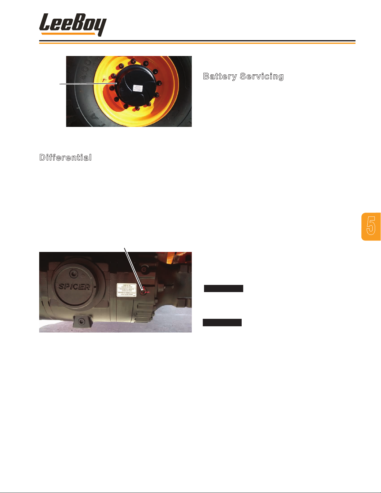
Planetary
Hub
Plug
Figure 4-17. Planetary Hub Plug
Differential Oil Plug
Differential
Maintenance
ELECTRICAL SYSTEM
Battery Servicing
The loader electrical system is a 12-volt negative ground
system.
NOTE: The electrical system is a negative ground
system. Connect the positive (+) cable to
the positive (+) post of the battery. Connect
the ground cable to the negative (-) post of
the battery. It is advisable to disconnect the
negative (-) cable rst and reconnect it last.
Reversed polarity can damage the electrical
system.
The differential plug is located at the back of the rear
axle under the machine. (Figure 5-18)
To check the differential gear oil level:
1. Shut down machine and apply park brake.
2. Unscrew the differential gear oil plug.
3. Oil should be level with bottom of the plug hole.
4. Fill if needed.
Figure 4-18. Differential Fluid Fill Location
Clean terminals and battery posts thoroughly and check
that battery cable terminals are tight. Dirty or loose
connections can create high electrical resistance and
permit arcing, which will quickly burn and pit terminals
and posts.
Keep the battery clean by washing it off whenever dirt
buildup is excessive. If corrosion is present around
terminal connections, remove them and wash with
ammonia solution or a solution consisting of 1/4 lb. (11 kg)
baking soda added to one quart of warm water. Make
certain the vent caps are tight to prevent solution from
entering the cells. After cleaning, pour clean water over
the battery and surrounding area to wash the solution
away. Check vent cap breather openings to make sure
they are open.
Batteries contain sulfuric acid and
normally produce explosive gases that can cause
serious injury. DO NOT allow ames or sparks to
come near the battery.
When charging or working near a
battery, always shield your face and protect your
eyes. In case of acid contact with skin or eyes,
ush immediately with water for a minimum of 15
minutes and get prompt medical attention. If acid is
swallowed, call a physician immediately.
5
3000C Force Feed Loader 5-17
Page 72
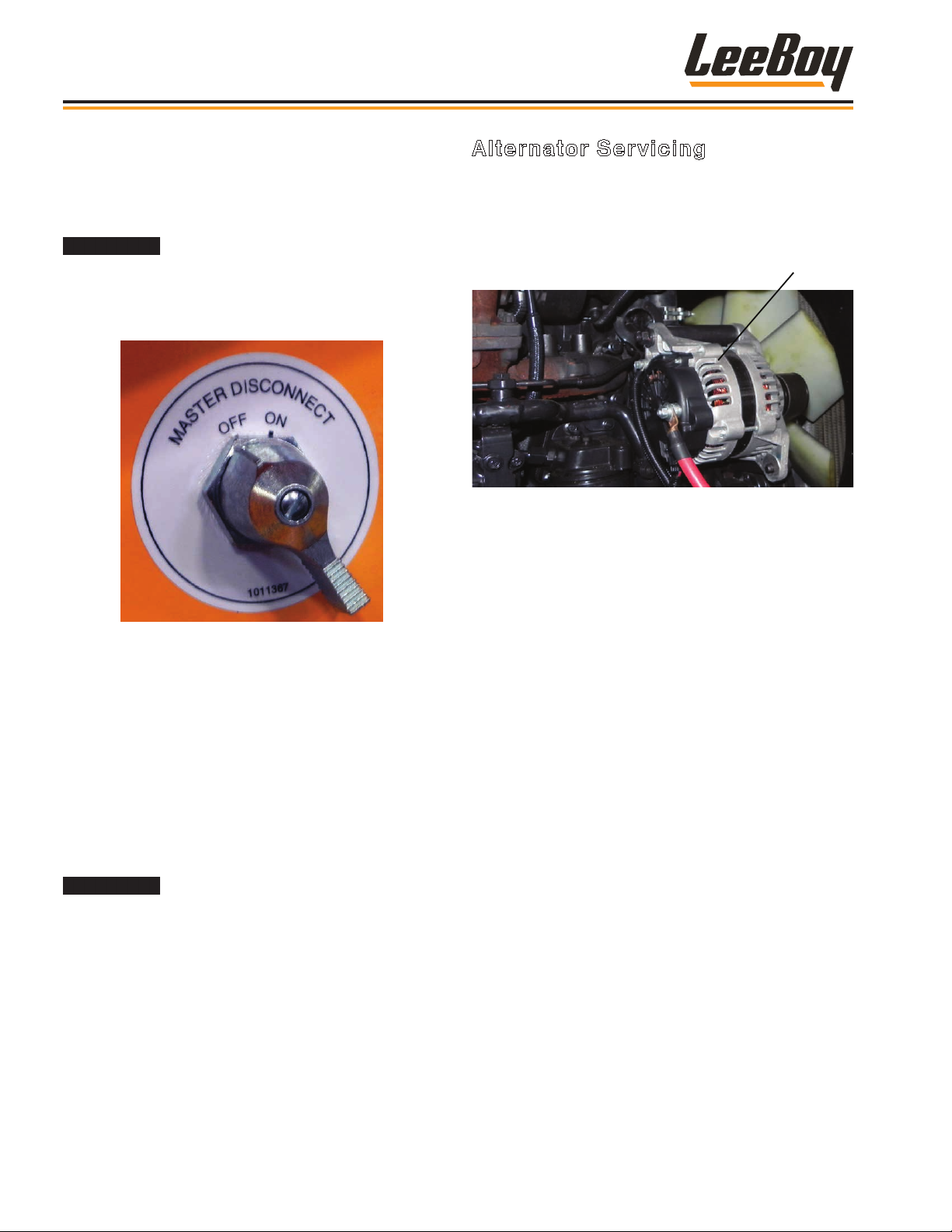
Alternator
Maintenance
When replacing the battery, discard the old battery
properly. Before connecting the battery, be sure the
Master Disconnect switch is turned off. The switch
is located on the conveyor control panel left of the
operator. (Figure 5-19)
When servicing the electrical system
or welding on the machine, always turn the Master
Disconnect switch to the OFF position to disconnect
the ground strap from the battery to prevent damage
to the machine electrical system.
Alternator Servicing
The alternator supplies electrical current for charging
the battery that provides electrical power to electronic
controls. The built-in regulator in the alternator controls
the voltage output. (Figure 5-20)
Figure 4-20. Alternator
If the wires must be disconnected from the alternator, be
sure to mark them for proper reconnection.
Use the following precautions to prevent damage to the
alternator for any maintenance performed:
Figure 4-19. Battery Disconnect Switch
Be sure to keep the battery fully charged during cold
weather to keep it from freezing. Freezing weather has
little effect on a fully charged battery.
When connecting a booster battery, if necessary for
cold weather starting, connect one end of the rst
jumper cable to the positive (+) terminal of the dead
battery and the other end to the positive (+) terminal of
the booster battery. Connect one end of the second
jumper cable to the negative (-) terminal of the booster
battery and the other end to the frame of the machine
with the dead battery.
DO NOT attach the negative (-) cable
from the booster battery to the negative (-) post of
the dead battery because a spark could cause an
explosion.
• Always disconnect the battery before disconnecting
or connecting the alternator.
• An alternator should never be polarized. DO NOT
ground any alternator terminals or circuits.
• Never disconnect the alternator while the machine is
operating.
• Be certain the wiring is properly connected before
connecting the battery.
3000C Force Feed Loader5-18
Page 73
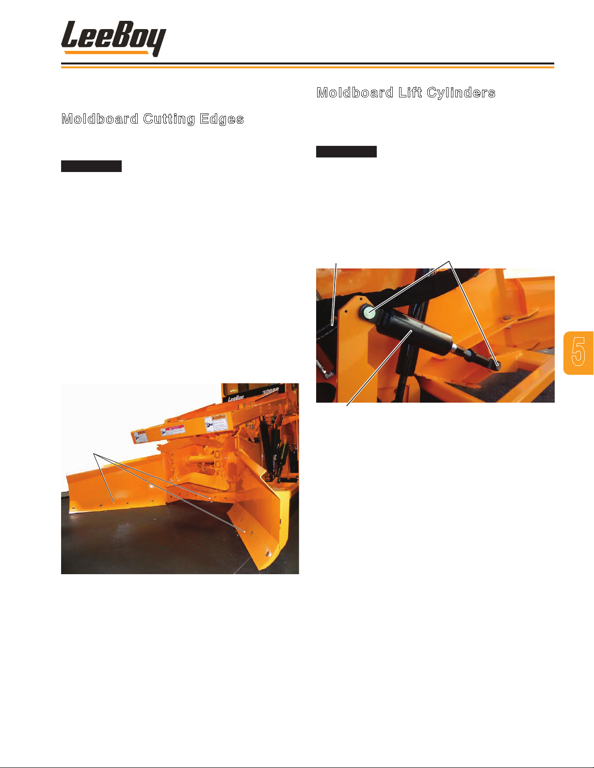
Maintenance
REPLACING COMPONENTS
Moldboard Cutting Edges
The moldboard cutting edge needs to be replaced if
worn. (Figure 5-21)
Engine must be turned off and the
wheels blocked to prevent motion when servicing the
machine. Also block moldboard to prevent injury.
Replace the cutting edge as follows:
1. Raise the moldboards off the ground.
2. Turn off engine and block the wheels to prevent
movement. Block moldboard off the ground as high
as possible.
3. Clean the area around the cutting edge.
4. Remove the four plow bolts, washers and nuts
securing the cutting edge. Remove cutting edge.
5. Attach a new cutting edge with the plow bolts,
washers and nuts .
6. Torque nuts to 105 ft-lb (145 N.m).
7. Lower moldboard, ensuring it is at on the surface.
Moldboard Lift Cylinders
The moldboard cylinders are located on both sides of
the machine behind the moldboard. These cylinders
should be replaced if damaged or inoperable.
Before breaking circuit connections,
ensure power is off and system pressure has been
released. Lower all vertical cylinders, discharge any
accumulators, and block any load that could move
and generate pressure.
NOTE: Plug and cap all lines and ports when
disconnected to prevent entry of dirt into
the system.
Hoses
Pins
5
Moldboard Cutting Edges
Figure 4-21. Moldboard Cutting Edges
Cylinder
Figure 4-22. Moldboard Lift Cylinders
1. Place a container under the cylinder to catch any
hydraulic oil when the lines are disconnected.
2. Disconnect and label the two hoses connected to
cylinder ttings. (Figure 5-22)
3. Remove the two clevis pins and cotter pins,
securing cylinder.
4. Remove cylinder from machine.
5. Install new cylinder.
6. Reinstall the two clevis pins and cotter pins.
7. Reconnect the two hydraulic hoses.
8. Add hydraulic oil, if needed.
9. Start the engine and operate the cylinder to check
for any leaks and proper operation.
3000C Force Feed Loader 5-19
Page 74
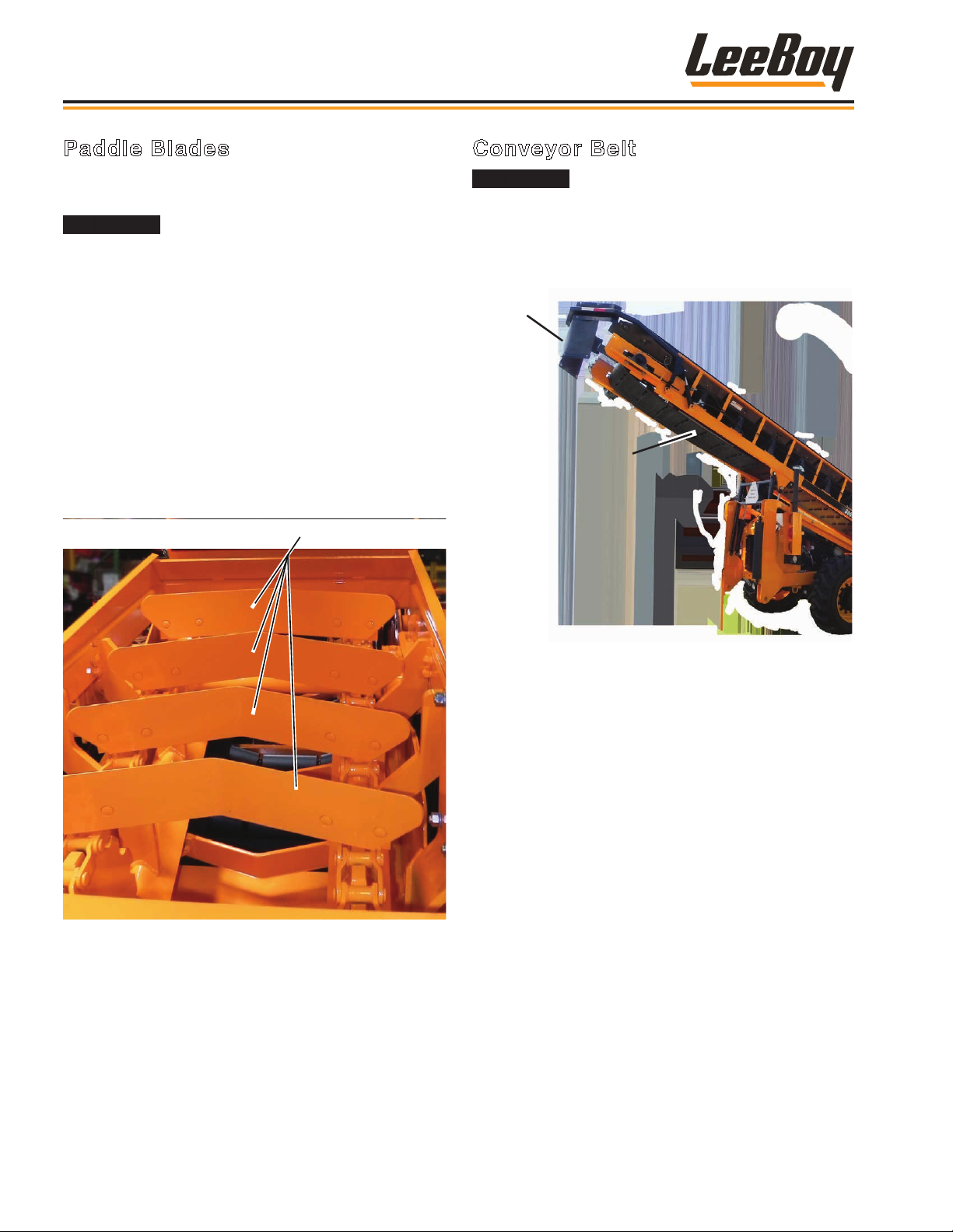
Paddle Blades
Maintenance
Paddle Blades
The paddle blades need to be replaced when damaged.
(Figure 5-23)
Engine must be turned off and the
wheels blocked to prevent motion when servicing the
machine.
Replace the paddle blade as follows:
1. Turn off engine and block the wheels to prevent
movement while working on the machine.
2. Clean the area around the paddle blade.
3. Remove the four plow bolts and nuts securing the
paddle blade to the chain assembly. Remove the
paddle blade..
4. Attach a new paddle blade and reinstall the four
plow bolts and nuts.
5. Torque plow bolts to 150 ft-lb (205 N.m).
Conveyor Belt
The conveyor belt weighs nearly
400 pounds. It will require more than one person to
replace the belt.
NOTE: When installing a belt, use the old belt to
pull the new belt onto the machine.
Deflector
Conveyor
Belt
Figure 4-23. Paddle Blades
Figure 4-24. Conveyor
For conveyor belt replacement, proceed as follows
(Figure 5-24):
1. Move the existing belt so that the belt joint is on the
top surface near the conveyor head pulley bearing.
2. Remove the belt lacing pin to disengage the belt.
3. Attach one end of the new belt to the top of the old
belt. Attach the belts together with the lacing pin.
4. Slowly thread the new belt around the pulleys back
to the tail pulley group while removing the old belt
from the conveyor.
5. Stop the machine when the end of the new belt is on
top of the pulley group.
6. Remove lacing pin and move old belt clear of the
area.
7. Secure the two ends of the new belt together with
lacing pin.
8. Check that the new belt is properly adjusted and
centered.
3000C Force Feed Loader5-20
Page 75
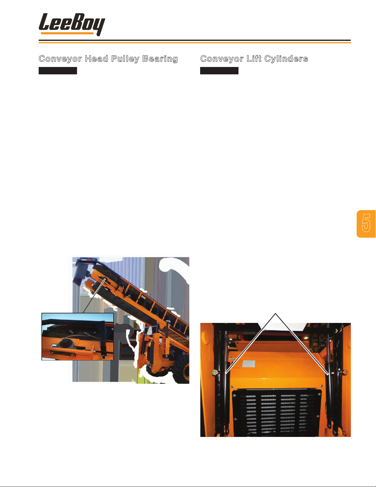
Conveyor Head
Pulley Bearing
Maintenance
Conveyor Head Pulley Bearing
This procedure should only be
performed while the machine is not operating.
1. Check that machine is turned off and remove key
from the ignition.
2. Remove the two caps screws and associated
hardware on the bearing. (Figure 5-25)
3. Slide the bearing from the shaft and remove from
machine.
4. Clean mounting surface.
5. Slide new bearing onto shaft.
6. Reinstall front cap screw through bearing mount
and hole in frame.
7. Attach nut and washers to cap screw, but do not
tighten.
8. Reinstall rear cap screw through a washer, then
through the adjusting bolt and mounting hole in the
frame.
9. Reattach nut and washers to cap screw.
10. Torque both nuts to 375 ft-lb (508 N.m).
11. Lubricate bearing.
Conveyor Lift Cylinders
Before breaking circuit connections,
ensure power is OFF and the system pressure
has been released. Lower all vertical cylinders,
discharge any accumulators, and block any load that
could move and generate pressure.
NOTE: Plug and cap all lines and ports when
disconnected to prevent dirt from entering
the system.
1. Insert safety pins into conveyor support. (Page
4-4) Or use a hoist when replacing conveyor lift
cylinders.
2. Place a container under the cylinder to catch
hydraulic oil when the lines are disconnected.
(Figure 5-26)
3. Disconnect and label the two hoses connected to
cylinder ttings.
4. Remove the two clevis pins and clip pins attaching
the cylinder to the frame and conveyor.
5. Remove old cylinder from machine and replace with
new cylinder.
1. Reinstall the two clevis pins and clip pins to secure
the cylinder.
5
2. Connect the two hydraulic hoses.
3. Add hydraulic oil, if needed.
4. Start the engine and operate the cylinder to check
for leaks and for proper operation.
Conveyor
Lift Cylinders
Figure 4-25. Conveyor Head Pulley Bearing
Figure 4-26. Conveyor Lift Cylinder
3000C Force Feed Loader 5-21
Page 76
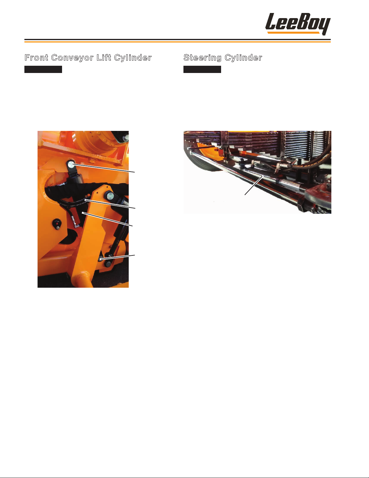
Maintenance
Front Conveyor Lift Cylinder
Before breaking circuit connections,
ensure power is OFF and the system pressure
has been released. Lower all vertical cylinders,
discharge any accumulators, and block any load that
could move and generate pressure.
NOTE: Plug and cap all lines and ports when
disconnected to prevent dirt from entering
the system.
Pin
Hoses
Cylinder
Steering Cylinder
Before breaking circuit connections,
ensure power is OFF and the system pressure
has been released. Lower all vertical cylinders,
discharge any accumulators, and block any load that
could move and generate pressure.
NOTE: Plug and cap all lines and ports when
disconnected to prevent dirt from entering
the system.
Steering Cylinder
Figure 4-28. Steering Cylinder
1. Place a container under the cylinder to catch
hydraulic oil when the lines are disconnected.
Pin
Figure 4-27. Conveyor Lift Cylinder
1. Place a container under the cylinder to catch
hydraulic oil when the lines are disconnected.
2. Disconnect and label the two hoses connected to
cylinder ttings. (Figure 5-27)
3. Remove the two clevis pins and clip pins attaching
the cylinder to the frame and conveyor.
4. Rest conveyor on blocks.
5. Remove old cylinder from machine and replace with
new cylinder.
6. Reinstall the two clevis pins and clip pins to secure
the cylinder.
7. Connect the two hydraulic hoses.
8. Add hydraulic oil, if needed.
2. Disconnect and label the two hoses connected to
cylinder ttings. (Figure 5-28)
3. Remove the two nuts and clip pins attaching the
cylinder to the axle and king pin.
4. Remove old cylinder from machine and replace with
new cylinder.
5. Reinstall the two nuts and clip pins to secure the
cylinder.
6. Connect the two hydraulic hoses.
7. Add hydraulic oil, if needed.
8. Start the engine and operate the cylinder to check
for leaks and proper operation.
9. Start the engine and operate the cylinder to check
for leaks and proper operation.
3000C Force Feed Loader5-22
Page 77
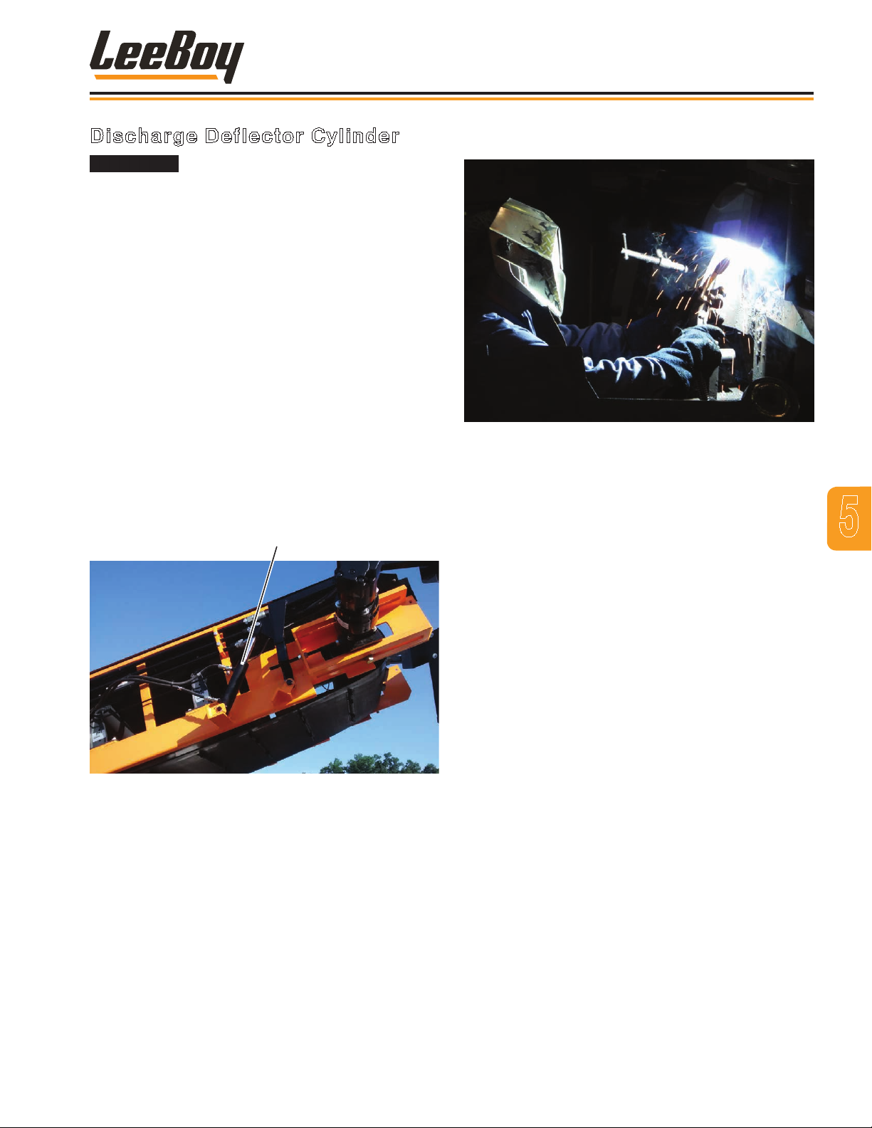
Maintenance
Discharge Deflector Cylinder
Before breaking circuit connections,
ensure power is OFF and the system pressure
has been released. Lower all vertical cylinders,
discharge any accumulators, and block any load that
could move and generate pressure.
NOTE: Plug and cap all lines and ports when
disconnected to prevent dirt from entering
the system.
There is a discharge deector cylinder on each side of
the conveyor.
NOTE: Replace one cylinder at a time so the other
supports the deector.
1. Place a container under the cylinder to catch
hydraulic oil when the lines are disconnected.
2. Disconnect and label the two hoses connected to
cylinder ttings. (Figure 5-29)
3. Remove the two clevis pins and clip pins attaching
the cylinder to the frame and conveyor.
Discharge Deflector Cylinder
WELDMENT
Figure 4-30. Welding
If the machine has been damaged or metal parts worn
due to extensive use, minor welding may be necessary
for repair. Welding is very dangerous. Only individuals
who are properly trained should weld in a dedicated area
away from others as even looking at ultraviolet light from
the ame can cause serious eye injury.
5
Figure 4-29. Deector Cylinder
4. Remove old cylinder from machine and replace with
new cylinder.
5. Reinstall the two clevis pins and clip pins to secure
the cylinder.
6. Connect the two hydraulic hoses.
7. Add hydraulic oil, if needed.
8. Start the engine and operate the cylinder to check
for leaks and for proper operation.
Welding hazards include toxic fumes, harmful dust,
light radiation, burns, combustion from sparks and the
potential for extensive damage to the eye. There is also
a danger of electric shock. If combustible or ammable
materials are nearby, the heat and sparks produced by
welding can cause res or explosions.
TURN THE BATTERY SWITCH OFF AND DISCONNECT
BATTERY TERMINALS BEFORE WELDING ON THE
MACHINE.
Electrical current can ignite re or cause an explosion,
therefore it is critical to turn off power to the machine. It
is also important to grind off the paint to ensure proper
ground on the area being welded.
DO NOT MAKE MODIFICATIONS TO THE MACHINE.
ONLY weld if needed for repair purposes. Weldment
modications to the machine can void your warranty.
3000C Force Feed Loader 5-23
Page 78
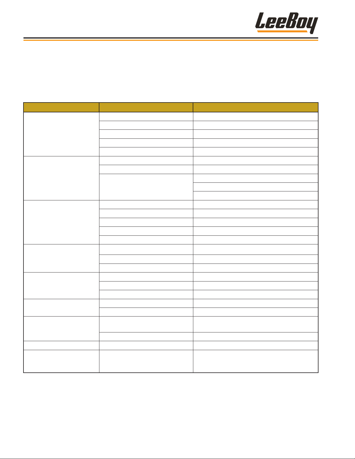
Maintenance
TROUBLESHOOTING CHART
The troubleshooting charts below identify the most
common symptoms of failure. Use these charts to help
identify the failed component and possible remedies.
Table 1-1. Troubleshooting Chart
SYMPTOM CAUSE REMEDY
Battery low. Check batteries.
Ignition switch defective. Check ignition switch.
Engine won’t turn over.
Engine won’t start but does
turn over.
Machine won’t move..
Hydraulic control valve
doesn’t function.
Parking brake will not
release.
Conveyor belt inoperable.
Foot pedal brake doesn’t
function.
Conveyor belt locks. Conveyor jam. Run conveyor belt in reverse to release jam.
Conveyor belt slips. Conveyor belt too loose.
Controls not in neutral. Check safety neutral switches.
Engine ground corroded. See Engine Operator’s Manual.
E-STOP is engaged. Manually release emergency stop.
Low fuel level. Check fuel in tank.
Contaminated fuel. Drain fuel tank and rell.
Fuel ow cut-off.
Hydraulic uid level low. Check hydraulic oil level.
Drive cable improperly attached.. Check drive cable connections.
Parking brake not released. Release emergency stop brake.
Drive motor defective. Check drive motor.
Hydraulic pump pressure too low. Check hydraulic pump pressure.
Hydraulic oil level too low. Check hydraulic oil level.
Relief valve stuck. Check relief valve to see if stuck open.
Suction lter clogged. Check hydraulic suction lter.
Parking brake switch defective. Check parking brake switch.
Brake circuit not complete. Check wire connections.
Solenoid valve defective. Check solenoid valve.
Hydraulic uid level low. Check hydraulic uid level.
Hydraulic lter clogged. Check hydraulic uid lter.
Insufcient pressure in brake
system
Pressure switch defective. Check charge valve.
If the problem persists, see your authorized LB
Performance Dealer.
Check fuel cut-off.
Check power to fuel cut-off.
See engine manual.
Check pressure at caliper (should be 1700 psi).
Loosen lock nut, then tighten set screw back
to lock nut. Tighten lock nut. Repeat until belt
does not slip.
3000C Force Feed Loader5-24
Page 79

Section 6
SCHEMATICS
Page
Group, Relays, Grid Heater . . . . . . . . . . . . . . . . . . . . . . . . . 6-3
Panel, Instrument, Top Right (1 of 2) . . . . . . . . . . . . . . . . . . . . . 6-5
Panel, Instrument, Top Right (2 of 2) . . . . . . . . . . . . . . . . . . . . 6-7
Panel, Instrument, Lower Right . . . . . . . . . . . . . . . . . . . . . . . 6-9
Harness, Main (1 of 2) . . . . . . . . . . . . . . . . . . . . . . . . . . . . 6-11
Harness, Main (2 of 2) . . . . . . . . . . . . . . . . . . . . . . . . . . . 6-13
Harness, Engine (1 of 2) . . . . . . . . . . . . . . . . . . . . . . . . . . 6-15
Harness, Engine (2 of 2) . . . . . . . . . . . . . . . . . . . . . . . . . . 6-17
Schematic, Electrical (1 of 2) . . . . . . . . . . . . . . . . . . . . . . . . 6-19
Schematic, Electrical (2 of 2) . . . . . . . . . . . . . . . . . . . . . . . . 6-21
Harness, Emission Sensor . . . . . . . . . . . . . . . . . . . . . . . . . 6-23
Hydraulic Schematic (1 of 2) . . . . . . . . . . . . . . . . . . . . . . . . 6-25
Hydraulic Schematic (2 of 2) . . . . . . . . . . . . . . . . . . . . . . . . 6-27
Hydraulic Hose Schematic (1 of 3) . . . . . . . . . . . . . . . . . . . . . 6-29
Hydraulic Hose Schematic (2 of 3) . . . . . . . . . . . . . . . . . . . . . 6-31
Hydraulic Hose Schematic (3 of 3) . . . . . . . . . . . . . . . . . . . . . 6-33
3000C Force Feed Loader
6-1
Page 80

Schematics
NOTES
6-2
3000C Force Feed Loader
Page 81
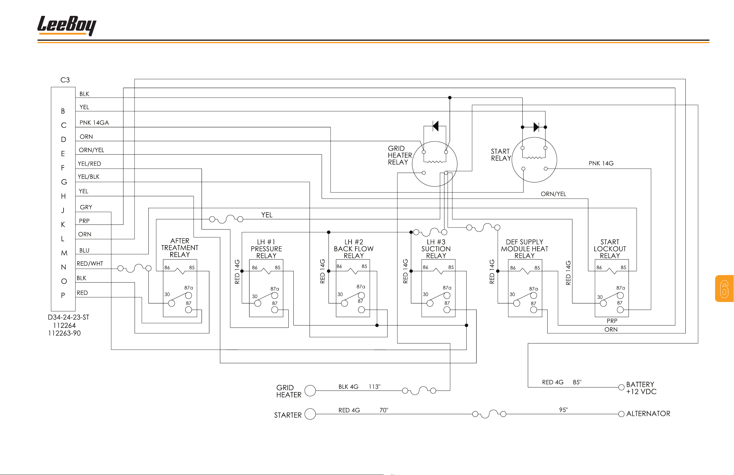
GROUP, RELAYS, GRID HEATER
Part # 1013393
A
Schematics
10A
5A
250A
15A
15A
7
6
175A
Figure 6-1. Schematic of Grid Heater Relays
3000C Force Feed Loader 6-3
Page 82

Schematics
NOTES
3000C Force Feed Loader6-4
Page 83
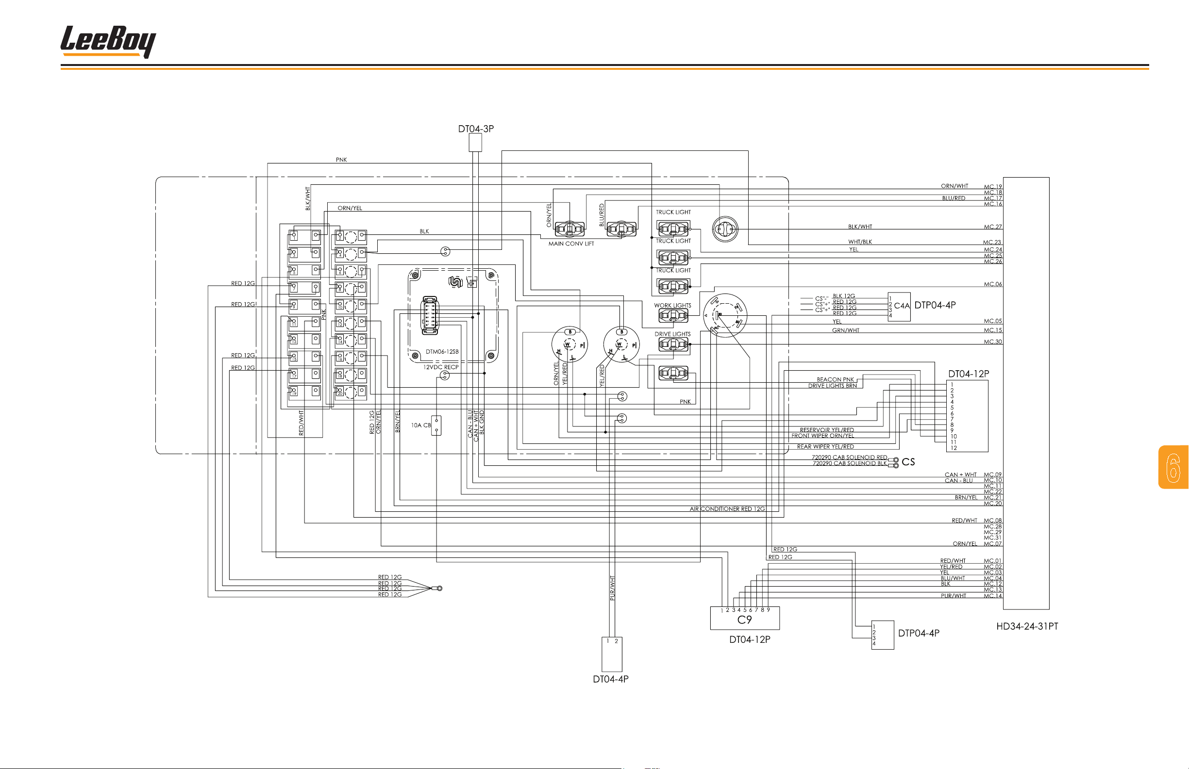
PANEL, INSTRUMENT, TOP RIGHT (1 OF 2)
Part # 1014275
CONNECTOR FOR
LOAD RESISTOR
A
B
Schematics
RED
BLU
ORN
BRN
BRN
BLU
WHT
WAIT TO START
BLU
RED
RED
BLU
RED
CAN SHIELD
WHT
PUR
FRONT
WINDOW
ORN
ORN
ORN
WINDOW
DEFLECTOR
REAR
WHT
LEFT FILTER
RIGHT FILTER
BLU
CENTER
BEACON
GRN
TOP
BOT
BRN
BLU
RED
PUR
RED
PUR
RED
HORN
BLU
IGNITION
BRN
REAR WIPER GRN
REAR WIPER WHT
FRONT WIPER ORN
FRONT WIPER LT BLU
RED
GRN
ORN
BLU
MC
CW
CAN SHIELD
RED
BLU
DOME LIGHT BRN
RED
BLU
CP
PUR
PUR
CE
CF
Figure 6-2. Schematic of Instrument Panel, Top Right - 1 of 2
3000C Force Feed Loader 6-5
7
6
Page 84

Schematics
NOTES
3000C Force Feed Loader6-6
Page 85
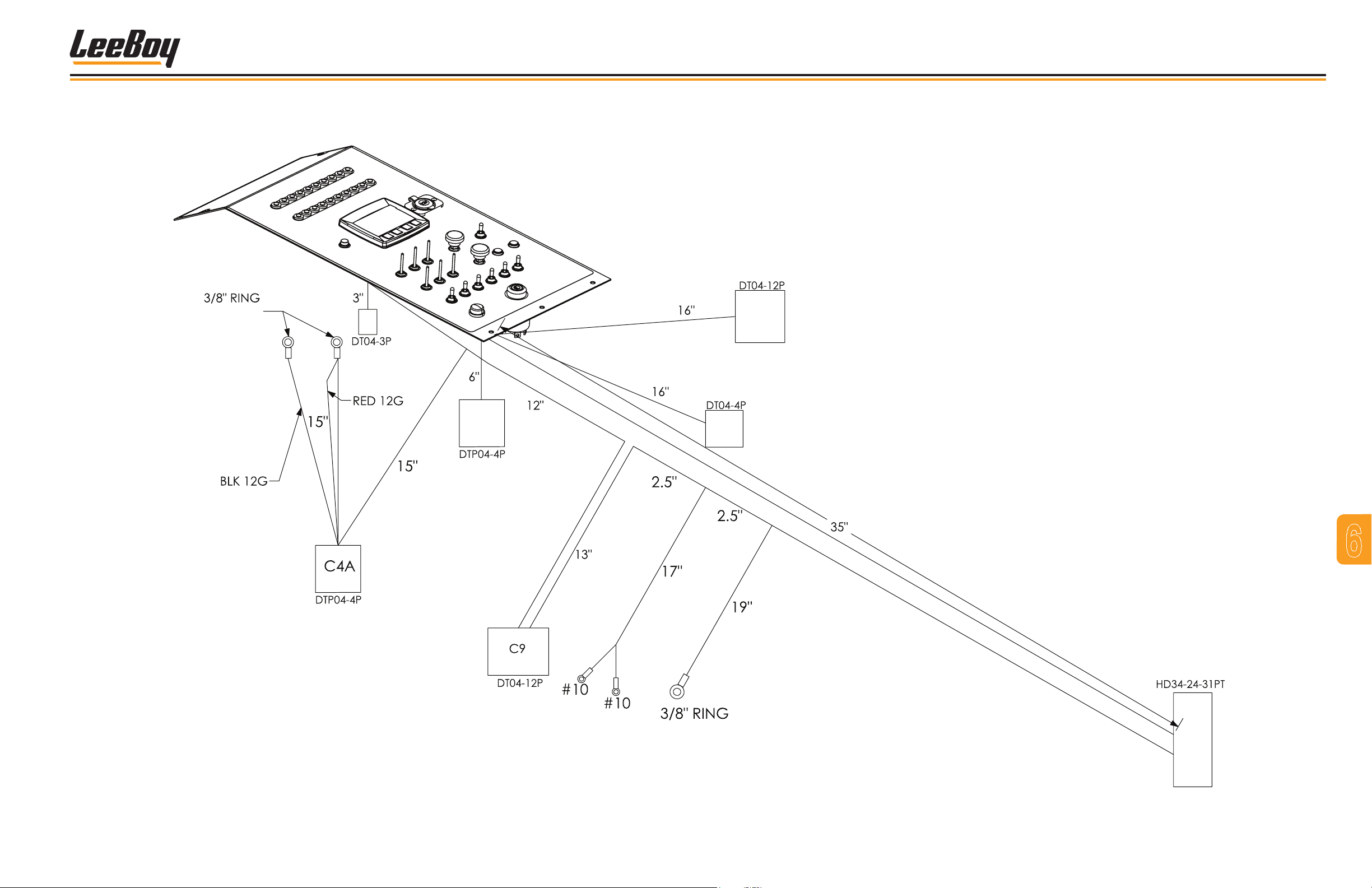
PANEL, INSTRUMENT, TOP RIGHT (2 OF 2)
Part # 1014275
Schematics
TERMINAL
CONNECTOR FOR
LOAD RESISTOR
CE
CF
CW
7
6
CP
CS
TERMINAL
Figure 6-3. Schematic of Instrument Panel, Top Right - 2 of 2
3000C Force Feed Loader 6-7
MC
Page 86

Schematics
NOTES
3000C Force Feed Loader6-8
Page 87
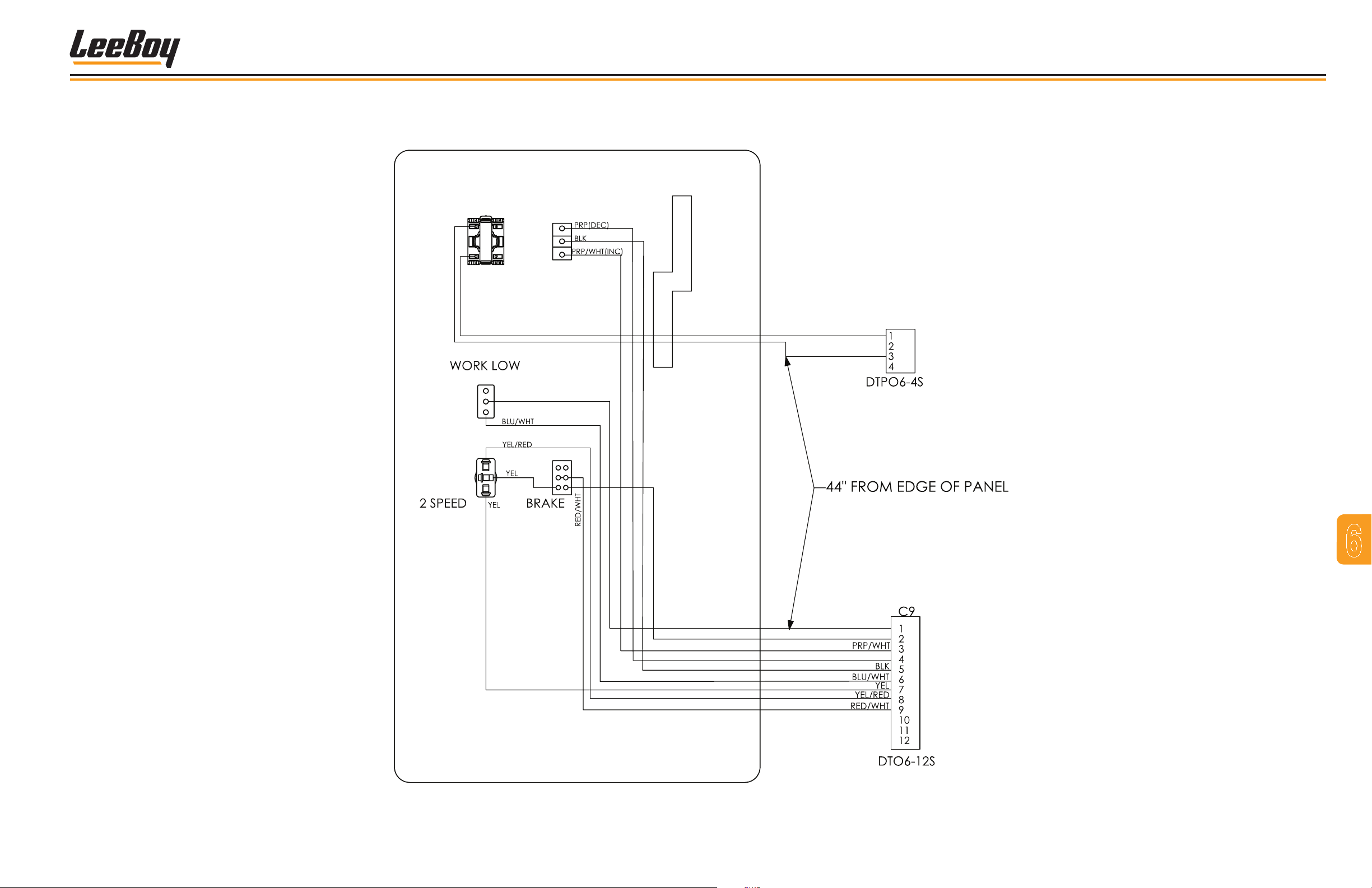
PANEL, INSTRUMENT, LOWER RIGHT
Part # 1011646
Schematics
ESTOP
THROTTLE
CE
BLU
RED
BLU
RED
PRP
Figure 6-4. Schematic of Instrument Panel, Lower Right
3000C Force Feed Loader 6-9
7
6
Page 88

Schematics
NOTES
3000C Force Feed Loader6-10
Page 89
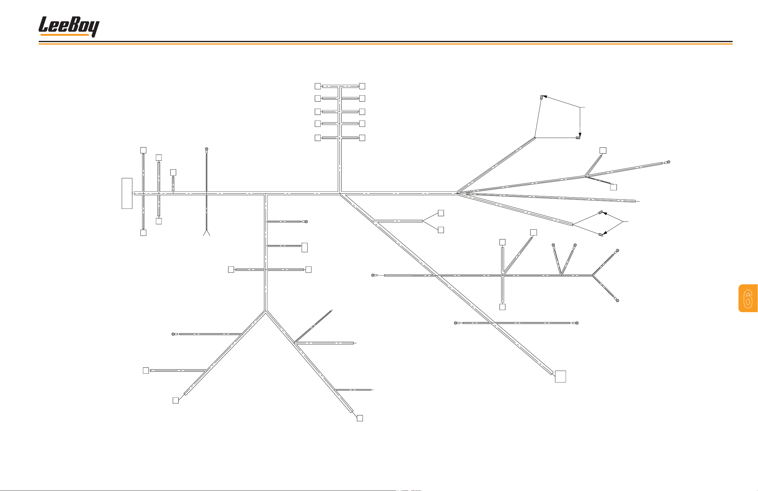
HARNESS, MAIN (1 OF 2)
Part # 1011644
BS
DT04-2P
1 BLK 10G(45)
20"
4"
12"
CF
DT06-4S
DT06-4S
CNAV
1 GRN(26)
2 YEL(24)
3 RED(25)
4 BLK(64)
2 RED 10G(42)
3 RED 10G(43)
4 RED10G(44)
6" 1"
1 RED/WHT
2 YEL/RED
3 YEL
4 BLU/WHT
5 YEL
6 BLU
7 ORN
8 RED/WHT
9 WHT
10 BLU
11 SHIELD
12 BLK
13 PRP
14 PRP/WHT
15 GRN/WHT
16 BLU
17 BLU/RED
18 ORN
19 ORN/WHT
20 BLU
21 BRN/YEL
22 RED
23 WHT/BLK
24 YEL
25 RED
26 GRN
27 BLK/WHT
28 YEL/RED
29 PNK
30 BRN
31 RED/WHT
RED(22) 1
BLK(64) 2
HD36-24-31ST
MC
PRP(46) 1
PRP/WHT(47) 2
C4A
DPT06-4S
RTS
DT06-2S
19"
7"
10"
SC
DT06-8S
1 GRN(34)
2 GRN/BLK(35)
3 RED(36)
4 RED/WHT(37)
5 WHT(32)
6 WHT/BLK(33)
7 BLU(38)
8 BLU/WHT(39)
GROUND
3/8"
BLK(64)
22"
DT04-4P
1 YEL(40)
2 ORN(60)
3 BRN(30)
4 BLKT(64)
1 YEL(40)
2 GRN(41)
CRTL
35"
22"
HYD TEMP
BRN/YEL(21)
56"
28"
YEL/RED(28)
PNK(29)
LO OIL CUTOFF(OPTION)
NEUTRAL START SWITCH
YEL(05) A
YEL(05.1) B
2 PIN WEATHERPAC
TOWER, MALE PINS
40"
2"
60"
13" 11"
12"
23"
7"
6"
60"
DT06-2S
SM CONV DEF
DT06-2S
SM CONV LIFT
DT06-2S
SM CONV SW
DT06-2S
MAIN CONV LIFT
DT06-2S
MAIN DEF
8"
4"
13"
RED(36) 1
BLK(64) 2
GRN(34) 1
BLK(64) 2
WHT(32) 1
BLK(64) 2
ORN(18) 1
BLK(64) 2
BLU(16) 1
BLK(64) 2
40"
HYD FILTER INDICATOR "R"
PRP(46)
DT04-3P
CBU
A ORN(60)
B ORN/YEL(07)
C GRN(61)
DT06-2S
DESTROKE
1 RED/WHT(62)
2 BLK(64)
15"
29"
8" 8"
8" 8"
8" 8"
8" 8"
8" 8"
WORK LIGHT
15"
Figure 6-5. Schematic of Main Harness - 1 of 2
2"
2"
2"
2"
9"
12"
HYD FILTER INDICATOR "L"
BLU(6.1)
HORN
BLK/WHT(27)
15"
14"
DT04-4P
1 GRN(41)
2 ORN(60)
3 BRN(30)
4 BLKT(64)
1 RED/WHT(37)
2 BLK(64)
1 GRN/BLK(35)
2 BLK(64)
1 WHT/BLK(33)
2 BLK(64)
1 ORN/WHT(19)
2 BLK(64)
1 BLU/RED(17)
2 BLK(64)
PRP/WHT(47)
BACK-UP
CLTL
ALARM
RED(60)
DT06-2S
SM CONV DEF
DT06-2S
SM CONV LIFT
DT06-2S
SM CONV SW
DT06-2S
MAIN CONV LIFT
DT06-2S
MAIN DEFBS
14"
4"
14"
Schematics
RED/WHT(08)
1/4" FEMALE
ORN/WHT(62)
2"
6"
+12VDC
3/8"
RED(42)
RED(43)
RED(44)
SPADE
DT06-2S
SWIVEL SOLENOID
1
2
2"
2"
RED/WHT(08)
BRAKE
LIGHT
2"
RED/WHT(31)
6"
6"
BLU/WHT(39)
BLK(64)
15"
DT06-2S
SWIVEL SOLENOID
1
BLU(38)
BLK(64)
2
YEL(05.2)
FEED NEUTRAL
YEL(05.3)
WORK LIGHT
BLU(06.2)
1/4" FEMALE
SPADE
FUEL SENDER
BLU(20)
7
6
2"
BRAKE
LIGHT
2"
12"
57"
6"
OVER REV
DT06-2S
3"
WORK LOAD
DT06-2S
3"
1 GRN(61)
2 BLK(64)
1 BLU/WHT(04)
2 BLK(64)
3"
GROUND
3/8"
BLK(45)
DT06-2S
2 SPEED HI
7"
4"
13"
4" 9"
1 YEL(03)
2 BLK(64)
DT06-2S
2 SPEED HI
1 YEL/RED(02)
2 BLK(64)
8"
DT06-2S
PARK BRAKE
1 RED/WHT(01)
2 BLK(64)
16"
27"
84"
CONVEYOR NEUTRAL
YEL(05.1) YEL(05.2)
6" 6"
12"
DT06-12S
1 BLK(12)
2 PRP/WHT(14)
C5
3 PRP(13)
4 GRN/WHT(15)
5 YEL(05.3)
6 WHT/BLK(23)
7 WHT(09)
8 LT BLU(10)
9 SHIELD(11)
3000C Force Feed Loader 6-11
Page 90

Schematics
NOTES
3000C Force Feed Loader6-12
Page 91
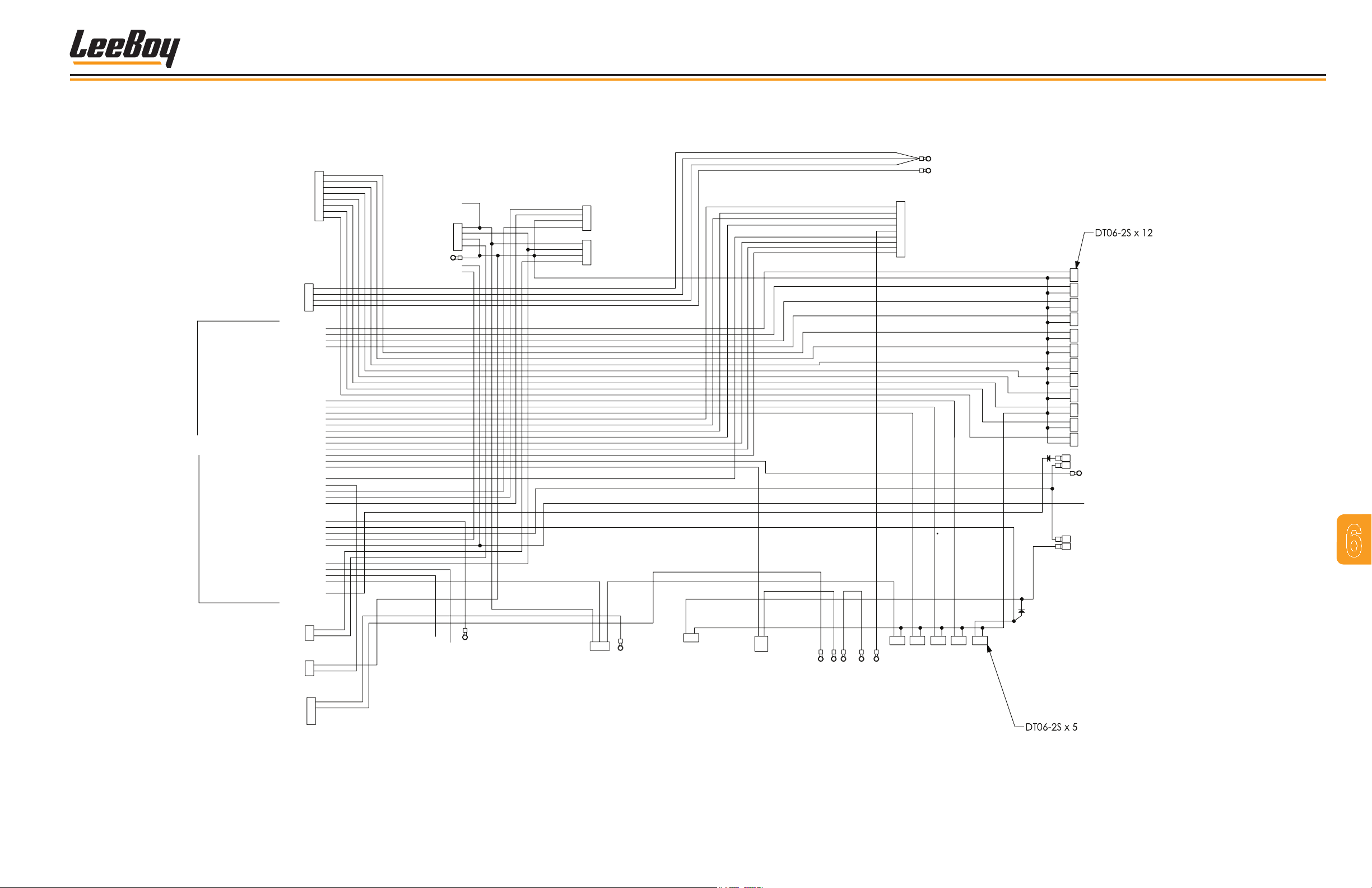
HARNESS, MAIN (2 OF 2)
Part # 1011644
SMALL CONVEYOR SWIVEL
SMALL CONVEYOR SWIVEL
SMALL CONVEYOR LIFT
SMALL CONVEYOR LIFT
SMALL CONVEYOR DEFLECTOR
SMALL CONVEYOR DEFLECTOR
MC
SC
SWIVEL SOLENOID
SWIVEL SOLENOID
C4A
12 VDC +
12 VDC +
12 VDC +
12 VDC -
MAIN DEFLECTOR
MAIN DEFLECTOR
MAIN CONVEYOR LIFT
MAIN CONVEYOR LIFT
HIGH LOW SWITCH
LOW LOW SWITCH
WORK LOW SWITCH
STARTER SOLENOID
BRAKE PRESSURE SWITCH
DOWN NAV LIGHT
HYD TEMP SENSOR
EMERGENCY STOP
42 RED 10GA
43 RED 10GA
44 RED 12GA
45 BLK 10GA
THROTTLE ISC1
THROTTLE DEC
THROTTLE INC
KEY SWITCH
J1939 HIGH
J1939 LOW
J1939 SHIELD
FUEL SENDER
WAIT TO START
UP NAV LIGHT
STOP NAV LIGHT
BRAKE LIGH
HORN
WORK LIGHT
PARK LIGHT
LOW OIL SWITCH
LOW OIL SWITCH
BACK UP
BRAKE
32 WHT
33 WHT/BLK
34 GRN
35 GRN/BLK
36 RED
37 RED/WHT
38 BLUE
39 BLU/WHT
DPT06-4S
3
17 BLU/RED
18 ORG
19 ORG/WHT
02 YEL/RED
04 BLU/WHT
14 PRP/WHT
15 GRN/WHT
11 SHIELD
23 WHT/BLK
22 RED
26 GRN
24 YEL
25 RED
21 BRN/YEL
01 RED/WHT
T
08 RED/WHT
27 BLK/WHT
30 BRN
28 YEL/RED
29 PINK
07 ORG/YEL
31 RED/WHT
DT06-8S
5
6
1
2
3
4
7
8
2
4
1
16 BLU
03 YEL
12 BLK
13 PRP
09 WHT
10 BLU
20 BLU
05 YEL
06 BLU
BACKUP ALARM
CLTL
LT REV LIGHT
LT PARK LIGHT
GROUND
LT TURN SIG
GROUND
WORK LIGHT
HORN
60 RED
DT04-4P
60 ORN
30 BRN
64 BLK
41 GRN
64 BLK
06.1 BLUE
27 BLK/WHT
Schematics
42 RED 10GA
43 RED 10GA
44 RED 12GA
45 BLK 10GA
DT06-4S
2
3
2
3
4
1
4
1
DT04-4P
2
3
4
1
24 YEL
25 RED
64 BLK
26 GRN
60 ORN
60 ORN
30 BRN
64 BLK
40 YEL
CNAV
UP NAV
STOP NAV
GROUND
DOWN NAV
CRTL
RT REV LIGHT
RT PARK LIGHT
GROUND
RT TURN SIG
3/8" RING
3/8" RING
DT06-12S
12 BLK
1
2
14 PRP/WHT
13 PRP
3
15 GRN/WHT
4
5
05.3 YEL
23 WHT/BLK
6
7
09 WHT
8
10 LT BLU
9
11 SHIELD
12 VDC +
12 VDC -
C5
ISC1 THROTTLE
INC THROTTLE
DEC THROTTLE
KEY SWITCH
NEUTRAL START SOLENOID
WAIT TO START
J1939 HIGH
J1939 LOW
J1939 SHIELD
16 BLU
1
2
64 BLK
1
17 BLU/RED
2
64 BLK
18 ORN
1
64 BLK
2
19 ORG/WHT
1
64 BLK
2
1
32 WHT
64 BLK
2
1
33 WHT/BLK
64 BLK
2
34 GRN
1
2
64 BLK
35 GRN/BLK
1
64 BLK
2
1
36 RED
1
64 BLK
2
2
1
1
37 RED/WHT
2
64 BLK
38 BLUE
1
1
222
64 BLK
11
39 BLUE/WHT
2
64 BLK
1/4" FEMALE SPADE
31 RED/WHT
08 RED/WHT
20 BLUE
06.2 BLUE
1/4" FEMALE SPADE
08 RED/WHT
62 ORN/WHT
MAIN DEFLECTOR
GROUND
MAIN DEFLECTOR
GROUND
MAIN CONVEYOR LIFT
GROUND
MAIN CONVEYOR LIFT
GROUND
SMALL CONVEYOR SWIVEL
GROUND
SMALL CONVEYOR SWIVEL
GROUND
SMALL CONVEYOR LIFT
GROUND
SMALL CONVEYOR LIFT
GROUND
SMALL CONVEYOR DEFLECTOR
GROUND
SMALL CONVEYOR DEFLECTOR
GROUND
SWIVEL SOLENOID
GROUND
SWIVEL SOLENOID
GROUND
BRAKE LIGHT SWITCH
BRAKE LIGHT
FUEL SENDER
WORK LIGHT
BRAKE LIGHT
DESTROKE SWITCH
7
6
RTS
RIGHT TURN SIGNAL
LEFT TURN SIGNAL
BS
BRAKE PRESSURE SWITCH
CF
HYD FILTER INDICATOR "R"
HYD FILTER INDICATOR "L"
DT06-2S
40 YEL
41 GRN
DT04-2P
64 BLK
22 RED
46 PRP
47 PRP/WHT
N/A
N/A
1
2
2
1
DT06-4S
1
2
3
4
29 PINK
21 BRN/YEL
28 YEL/RED
LOW OIL CUT OFF
LOW OIL CUT OFF
HYD TEMP SENSOR
DT04-3P
CBU
C
A
B
60 ORG N/O (3) BACK UP
46 PRP
07 ORG/YEL COM (1) BACK UP
61 GRN N/C (2)BACK UP
HYD FILTER INDICATOR "R"
2
1
DT06-2S
64 BLK
62 RED/WHT
DESTROKE
WEATHERPAC
A
B
05.1 YEL
05 YEL
NEUTRAL START
SWITCH
05.2 YEL
05.2 YEL
05.1 YEL
47 PRP/WHT
CONVEYOR SAFETY SWITCH
HYD FILTER INDICATOR "L"
05.3 YEL
FEED SAFETY SWITCH
FEED SAFETY SWITCH
CONVEYOR SAFETY SWITCH
1
2
61GRN
64 BLK
OVER REV
1
2
2 1
1
64 BLK
02 YEL/RED
64 BLK
04 BLUE/WHT
2 SPEED (LOW)
WORK LOAD
2
2
1
03 YEL
01 RED/WHT
64 BLK
64 BLK
2 SPEED (HIGH)
PARK BRAKE
Figure 6-6. Schematic of Main Harness - 2 of 2
3000C Force Feed Loader 6-13
Page 92

Schematics
NOTES
3000C Force Feed Loader6-14
Page 93
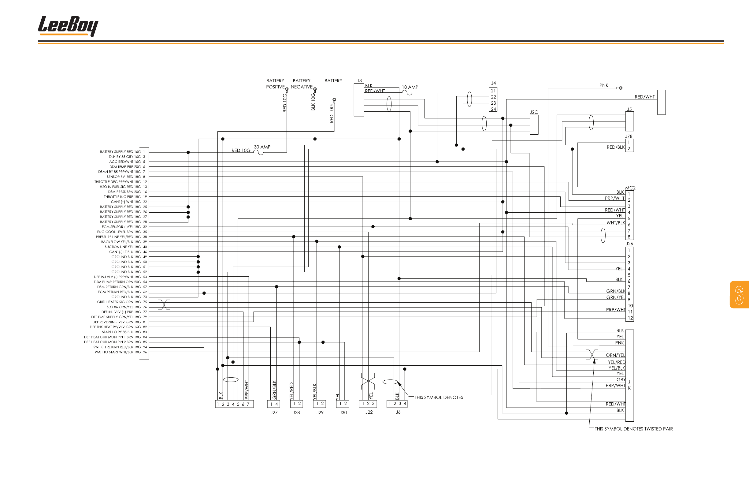
HARNESS, ENGINE (1 OF 2)
Part # 1013785
Schematics
ISOLATION
SWITCH
A
B
C
D
E
WHT
LT BLU
SHIELD
WHT
LT BLU
WHT
LT BLU
SHIELD
STARTER
SHIELD
A
B
C
LT BLU
WHT
RED
PRP
WHT
LT BLU
RED
BRN
A
B
C
ALTERNATOR
A
B
C
D
LT BLU
WHT
RED
EM SENSORS
SHIELD
PRP
GRN
RED
BRN
BRN
BRN
RED
BRN
LT BLU
WHT
Figure 6-7. Schematic of Engine Harness - 1 of 2
CAN BUS
ORN
PRP
ORN
ORN
ORN
BLU
RED
RP
A
B
C
D
E
F
G
H
L
M
N
O
P
7
6
3000C Force Feed Loader 6-15
Page 94

Schematics
NOTES
3000C Force Feed Loader6-16
Page 95
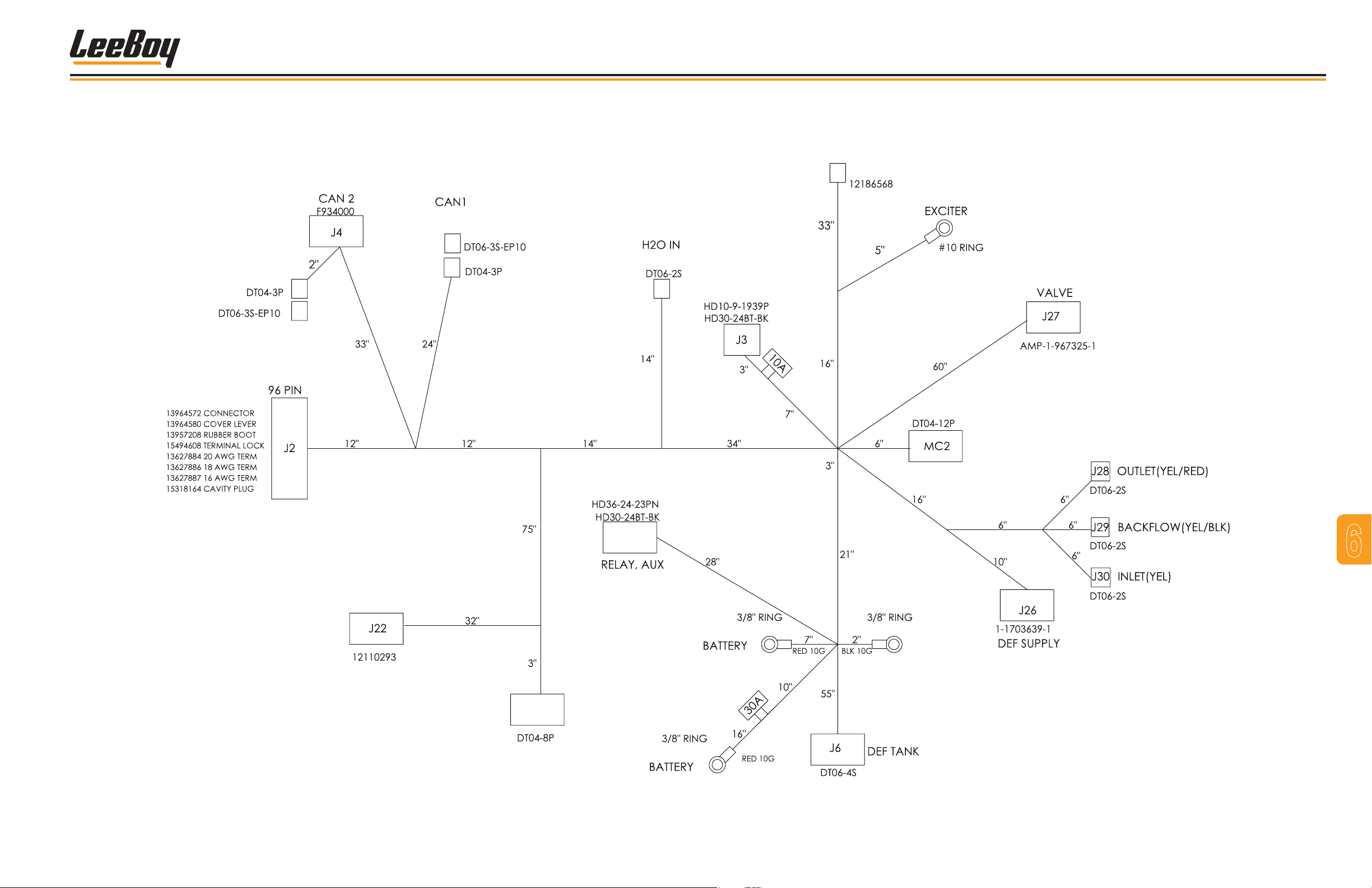
HARNESS, ENGINE (2 OF 2)
Part # 1013785
Schematics
ALTERNATOR
DELPHI
STARTER
LOAD
RESISTOR
LOAD
RESISTOR
PANEL
FUEL
TERMINAL
HARNESS
MAIN
COOLANT
CONTROL
7
6
ENGINE COOLANT
TERMINAL TERMINAL
ISOLATION
SWITCH
EMMISION
SENSORS
Figure 6-8. Schematic of Engine Harness - 2 of 2
3000C Force Feed Loader 6-17
TERMINAL
TERMINAL
FRAME
GROUND
MODULE
Page 96

Schematics
NOTES
3000C Force Feed Loader6-18
Page 97
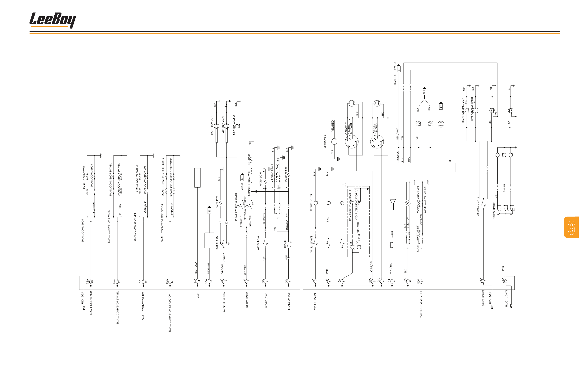
SCHEMATIC, ELECTRICAL (1 OF 2)
Part # 1014932
Schematics
SWITCH
BLU
SWITCH
WHT
SWITCH
GRN
SWITCH
RED
AIR
CONDITIONER
PRP
WHT
ORG
GRN
WHT
ORG
ORG
ORG
ORG
TURN SIGNAL SWITCH
P
P
W
BLU
M
WINDSHEILD WIPER
DOME LIGHT
BEACON LIGHT
BRN
L
H
I
FRONT WIPER
RED
HIGH
FRONT WIPER SWITCH
WASHER
GRN
B
LOW
ORG
PRP
L
H
I
REAR WIPER
RED
WHT
B
HIGH
WASHER
LOW
REAR WIPER SWITCH
OPTION
GRN
GRN
TURN SIGNAL SWITCH
HORN
RIGHT FRONT SIGNAL
GRN
DEFLECTOR
DEFLECTOR
LEFT FRONT SIGNAL
RED
ORG
GRN
GRN
RED
L
P
FLASHER
BLU
RED
RED
WHT
W
W
RIGHT REAR SIGNAL
RED
RED
RED
RED
BRN
BRN
A
UP
STOP
RED
WHT
GRN
RED
LEFT REAR SIGNAL
BRN
R
A
DOWN
GRN
7
6
CAB
SOLENOID
BLU
WHT
GRN
RED
RADIO
BLU
RED
R
R
DOME LIGHT
BEACON LIGHT
RED
BEACON
BRN
DOME
FRONT WIPER
1A
1B
1C
BLU
2A
2B
2C
HORN
WHT
REAR WIPER
HORN
DEFLECTOR
DEFLECTOR
ORG
BRN
IGN
SWITCH
CAB
SOLENOID
Figure 6-9. Electrical Schematic - 1 of 2
3000C Force Feed Loader 6-19
Page 98

Schematics
NOTES
3000C Force Feed Loader6-20
Page 99
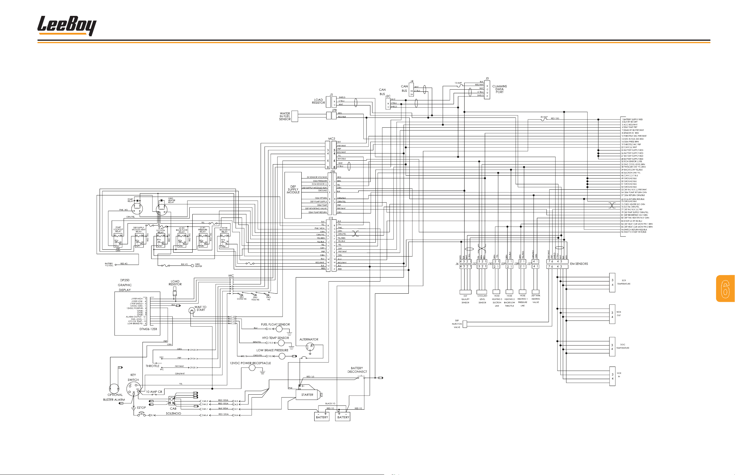
SCHEMATIC, ELECTRICAL (2 OF 2)
Part # 1014932
Schematics
21
22
A
1
1
2
2
1
1
1
2
2
5
5
5
727
7
1
1
2
2
5
5
7
7
10
10
11
11
12
12
15A
15A
5A
A
A
A
A
250A
50
17
10A
10
11
12
15
5
2
1
A
175A
5 2 1
15 2
2
1
7
6
2
1
2
1
2
1
Figure 6-10. Electrical Schematic - 2 of 2
3000C Force Feed Loader 6-21
Page 100

Schematics
NOTES
3000C Force Feed Loader6-22
 Loading...