

Page 1
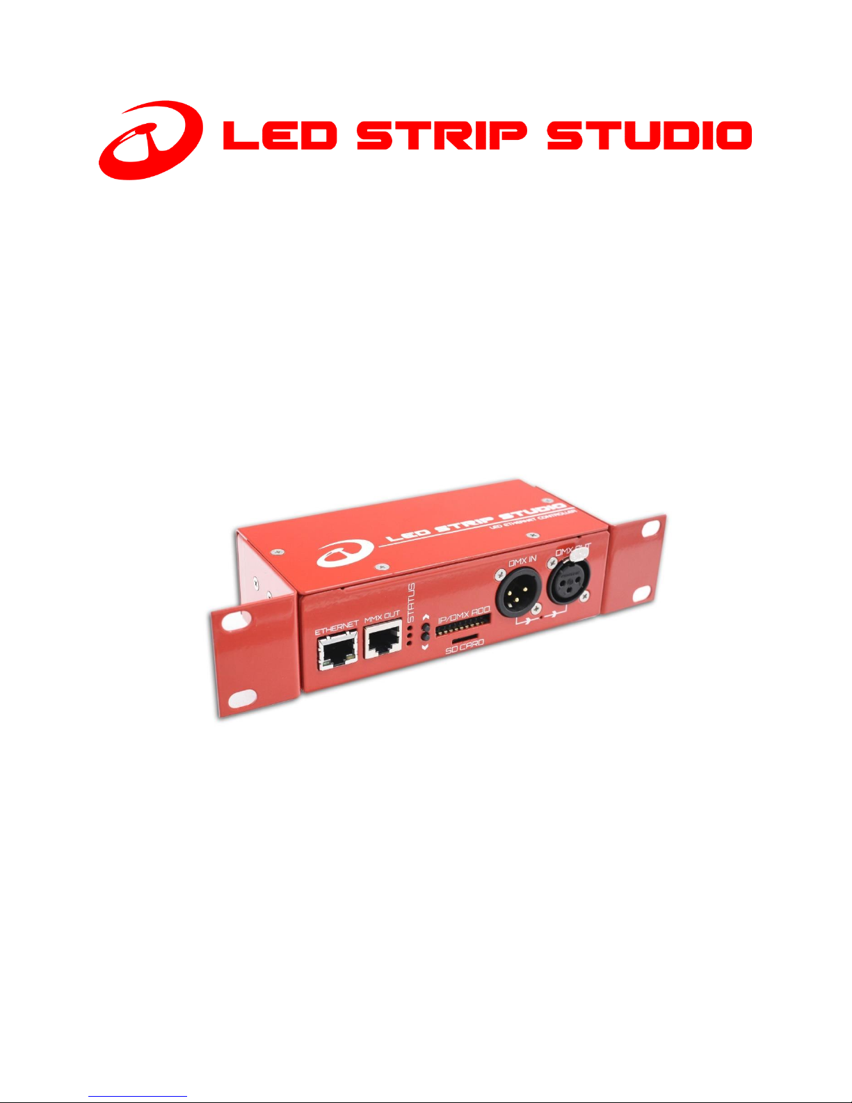
LED Ethernet Controller 3,
SPI-Matrix and
Powered LED Ethernet Controller
User manual
Page 2

CONTENT S
Contents ......................................................................................................................................................................... 2
General information....................................................................................................................................................... 5
Package content ......................................................................................................................................................... 5
Safety instructions ..................................................................................................................................................... 5
Disposal of your old device ........................................................................................................................................ 6
Trademark credits ...................................................................................................................................................... 6
Copyright .................................................................................................................................................................... 6
Technical details ............................................................................................................................................................. 7
LEC3, SPI-Matrix and Powered LED Ethernet Controller difference .......................................................................... 7
What can you control using the devices? .................................................................................................................. 8
LSS LED Strips, Hardware Specification .......................................................................................................................... 9
LED Strip Studio Software ............................................................................................................................................ 10
LED Ethernet Controller 3 (LEC3) device ...................................................................................................................... 11
Front connectors ...................................................................................................................................................... 12
Rear connectors ....................................................................................................................................................... 13
LEC3 dimensions ...................................................................................................................................................... 14
Distributor board ..................................................................................................................................................... 15
Sample LEC3 Ethernet/LSS Distributor configurations ............................................................................................. 17
SPI-Matrix ..................................................................................................................................................................... 18
POWERED LED Ethernet Controller.............................................................................................................................. 19
LEC3 Ethernet board DMX control ............................................................................................................................... 20
LED Strip Studio – Ethernet and signal connection scheme when using LEC3 ............................................................ 21
Connecting TM, WS, APA or SK family LED Strips with LEC3........................................................................................ 22
Direct connection ................................................................................................................................................. 22
Separate power supplies (more than 5A per LEC3 output) ................................................................................. 23
Connecting LEC3 with WS2801, WS2803 LED Pixels ................................................................................................ 24
Page 3

Detailed cable-connection for LED strips ................................................................................................................. 26
Recommended wire types ........................................................................................................................................... 27
Signal cables ............................................................................................................................................................. 27
Power cables 110-230V ............................................................................................................................................ 27
Power cables 5V DC ................................................................................................................................................. 27
LEC3 control modes ..................................................................................................................................................... 29
Ethernet mode ......................................................................................................................................................... 29
ArtNet mode ............................................................................................................................................................ 29
ArtNet Pixel Mode ................................................................................................................................................ 29
ArtNet SD-card mode ........................................................................................................................................... 30
DMX Mode ............................................................................................................................................................... 30
Auto-play mode ....................................................................................................................................................... 30
Testing mode............................................................................................................................................................ 30
DMX Out................................................................................................................................................................... 31
LEC3 Web Configuration .............................................................................................................................................. 32
Main menu ............................................................................................................................................................... 33
Status bar ................................................................................................................................................................. 33
Status ....................................................................................................................................................................... 34
Main Settings ....................................................................................................................................................... 34
Outputs ................................................................................................................................................................ 35
Autoplay ............................................................................................................................................................... 35
Art-Net/DMX ........................................................................................................................................................ 36
All Sett. ..................................................................................................................................................................... 38
Main Settings ....................................................................................................................................................... 38
Testing .................................................................................................................................................................. 38
Outputs ................................................................................................................................................................ 39
Autoplay ............................................................................................................................................................... 39
Art-Net/DMX ........................................................................................................................................................ 40
Account Settings .................................................................................................................................................. 41
Page 4

Notes: ....................................................................................................................................................................... 42
Page 5

GENERAL INFORMATION
This manual contains important instructions for the safe operation and installation of the unit. Read and follow the
safety instructions and all other instructions.
Keep this manual handy as a reference for operating procedures and safety information.
Specifications in this manual and design are subject to possible modifications
without notice due to improvements.
PACKAGE CON TE N T
The LEC3 package consists of:
• LEC3 controller
• L-shape mount brackets set including screws
• DIN rail mount including screws
• 5x suitable 4pin 5mm pitch cable side pluggable terminal block
• micro SD card
• micro SD card to SD card adapter
• micro SD card USB reader
SAFETY INST R U C TIONS
Installation should be performed only by a competent person or professional electrician.
Make sure that the installation complies with the standards and rules that apply in your country.
Do not use the device if it seems to be damaged.
Use the device only as described in this user manual. Any other use or use under other operating conditions is
improper and may result in personal injury or property damage. No liability will be assumed for damages resulting
from improper use.
Never open the controller and do not attempt repairs yourself.
Do not place the device close to heat sources and always ensure sufficient ventilation.
Do not place the unit on surfaces that are heat sensitive.
This device has been designed for indoor use only. Do not expose the unit to direct sunlight. Do not allow this
product to meet liquids. Electrical shock could result. Also, damage to the product, smoke, and overheating could
result from contact with liquids.
Clean the device components that are accessible from the outside regularly. The cleaning frequency depends on
the operating environment: damp, smoky or particularly dirty environments can cause greater accumulation of dirt
on the device components. Clean with a dry soft cloth. Stubborn dirt can be removed with a slightly dampened
cloth. Never use solvents or alcohol for cleaning.
Establish all connections when the unit is switched off. Use the shortest possible high-quality cables for all
connections. Make sure that cables cannot cause a trip hazard.
Never touch the plug contacts with sharp or metal objects.
Page 6

Ensure that plastic bags, packaging, etc. are disposed of properly and are not within reach of babies and young
children. Choking hazard!
Ensure that children do not detach any small parts (e.g. screws, connectors or the like) from the unit. They could
swallow the pieces and choke!
Never let children unattended use electrical devices.
DISPOSAL OF Y O UR OLD D E VICE
Dispose of this device through an approved waste disposal firm or through your local waste
facility. When discarding the device, comply with the rules and regulations that apply in your
country. If in doubt, consult your local waste disposal facility.
TR ADEMARK C R E DITS
Windows® is the registered trademarks of Microsoft® Corporation.
Art-Net™ – Designed by and Copyright Artistic License Holdings Ltd.
All other products mentioned herein may be trademarks of their respective companies.
COPYRIGHT
Showtacle Ltd. © 2018 All rights reserved.
Reproduction, adaptation, or translation without prior written permission is prohibited. Specifications in this
manual and design are subject to change without notice.
Page 7
TECHNIC AL DETAILS
This document will introduce you to correct hardware connection of LED strips and will provide the most
important technical details about LED Strip Studio (LSS) software and LED Ethernet Controller 3 (LEC3), SPIMatrix and Powered LED Ethernet Controller devices.
LEC3, SPI- M A TRIX AND P OWERED LED E T H ERNET C ONTROLLER DIFFERENCE
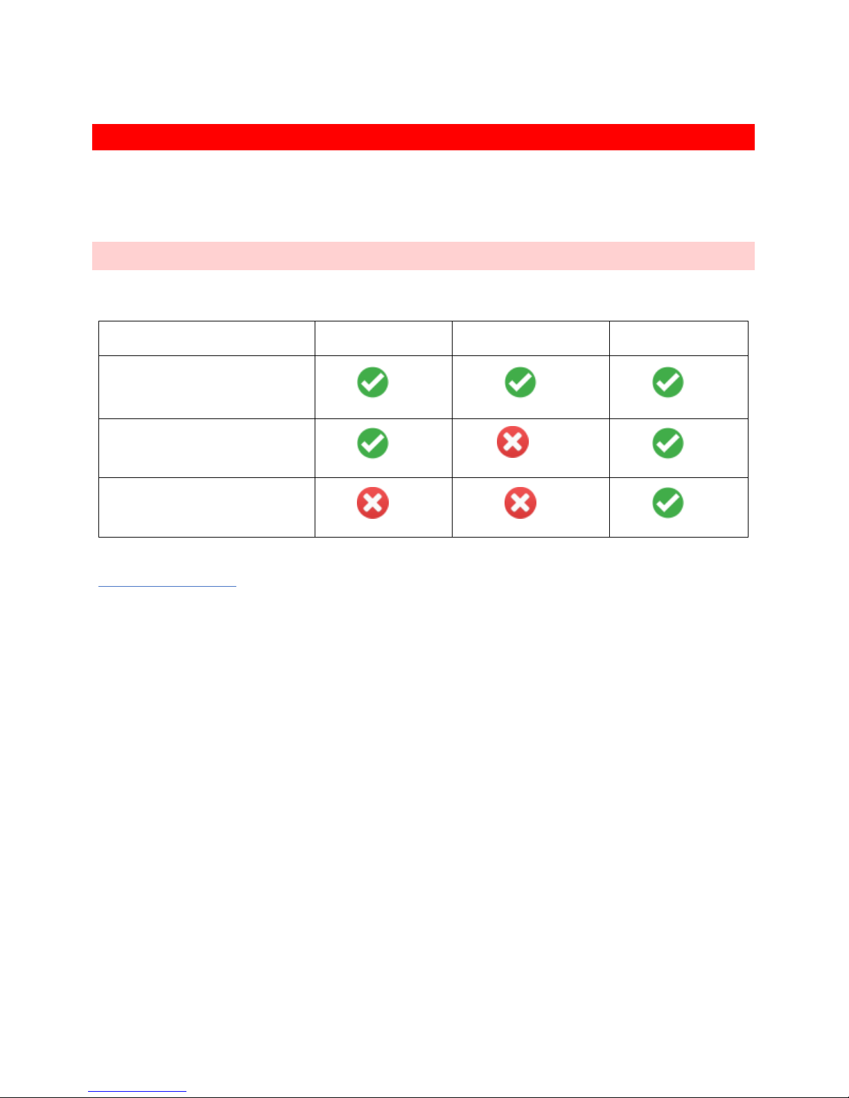
In the following table you can see the basic differences between all 3 devices.
(*) SPI-Matrix can be upgraded to LEC3 to support LED Strip Studio software. Contact us for more details at
Generally, SPI-Matrix is the same as LEC3, but without the support of LED Strip Studio software – you can’t use
it as LED Strip Studio software output device.
Powered LEC Ethernet Controller (Powered LEC) is the same as LEC3, but with integrated power source (320W,
5V, 60A).
LED Ethernet
Controller 3 (LEC3)
SPI-Matrix
Powered LED
Ethernet Controller
ArtNet (4096 individual LED
pixels over ArtNet)
LED Strip Studio software
(*)
Integrated power source
Page 8

WHAT CAN Y O U C ONTROL USING THE DE VICES?
There are many kind of digital LED lights you can control using LEC3. You can control digital LED strips, digital
LED pixels or any other special digital lights. They are also sometimes called dream or individual addressable
LED lights. We use “digital LEDs” or “digital pixels” in the text to address all kind of digital lights (like LED strips,
pixels, digital bulbs, …).
Digital LEDs can use different kind of chip to control RGB LED color. LEC3 is now able to use LED strips with TM,
WS or APA chips (and many more).
You can use LEC3 in 4 different modes:
• Ethernet (software)
• ArtNet
• DMX
• Stand-alone (SD-card mode)
ArtNet and DMX mode can work in two different ways: Pixel or SD-card player. In Pixel mode the DMX channels
are converted directly to pixels (3 channels for every pixel, maximum is 170 pixels per ArtNet Universe). In SD-card
player you can only trigger animation LED files stored on SD-card (so you don’t have to use complicated Art-Net or
DMX solution with tons of cables).
Page 9

LSS LED STRIPS, HARDWARE SPE C IFIC ATION
LED strips produced for LED Strip Studio are high quality LED strips developed completely by LED Strip Studio.
Here you can find basic technical details:
Strip type
STCL LED Strip 42
Number of LEDs
42 LEDs/meter
IC
SK6812 (TM1809 and WS2812B compatible)
LED pitch
23.8 mm
LED type
5050, ROHS compliant lead-free soldering compatible
Shortest working segment
1 LED, 2.38 cm
Colors
Full color, 24 bits, 16.7 million colors, C25050
Color channels
3 channels: Red, Green, Blue
Color shades
8 bit, 256 levels for every channel (3 * 256 colors)
Voltage
5V
Maximal current
1.2A/meter (at white color)
LED Size (mm)
5.4*5.0*1.6
LED Viewing angle
120°
LED Luminous intensity (mcd)
R: 700-1000, G: 1500-2200, B: 700-1000
LED Wavelength (nm)
R: 620-625, G: 522.5-525, B:467.5-470
Color temperature
Variable, set by RGB channels
Expected lifetime
30000+ hours
Reel weight (5m LED strip)
230g
Storage temperature range
-40° ~ +80°
Operating temperature range
-20° ~ +50°
Waterproof
Yes, IP65
Warranty
1 year
Page 10
LED STRIP STUDIO SOFTW ARE
LED Strip Studio software is the “main brain” of LED Strip Studio system. It can be used to play video, picture or
even live stream on video LED strips (or LED pixels). This is recommended PC configuration for LED Strip Studio
system. Of course, if the configuration is better, the software will work smoother.
Recommended PC configuration
Operating system
Windows 7, 8, 10
Processor
Dual Core (Intel Core2Duo and better)
Graphic card
Dedicated - nVidia or ATI/AMD (but new Intel HD
cards are also fine).
RAM
4GB
Hard disk
200 MB
Required software
DirectX 9.0c, Apple QuickTime
Grabber card for live stream
Yes, HDMI – BlackMagic Intensity PRO
MIDI control
supported
OSC control
supported
Touch screen
supported
Page 11
LED ETHERNET CONTROLL E R 3 (LEC3) DEVICE
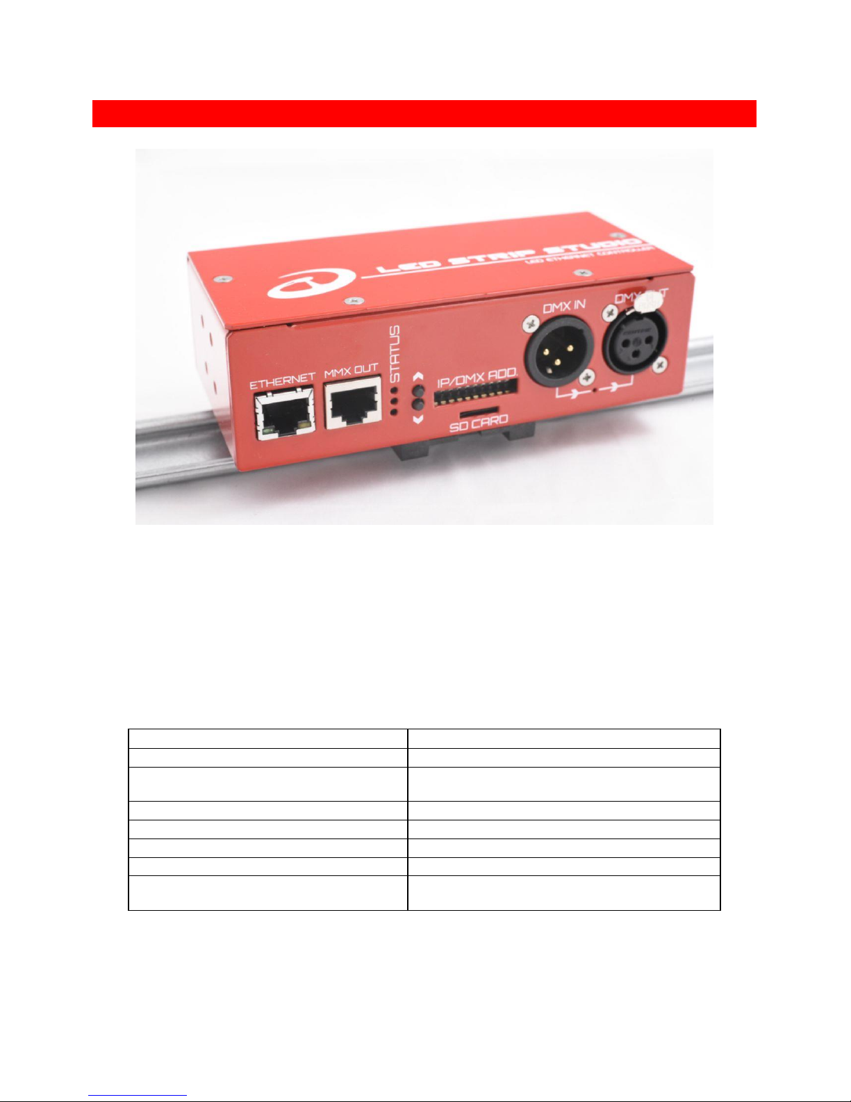
LEC3 device
LED Ethernet Controller 3 (LEC3) is main controller for digital LEDs (pixels, strips, bulbs, …). Using integrated DMX
output, you can also use it to control analog lights (like strips, pixels, PARs, …). This provides you with convenient
way to control all kind of LED lights using one controller.
It integrates Ethernet, DMX and ArtNet controller and stand-alone player for digital lights. It can control up to
4096 LEDs (4 outputs, each 1024 LEDs), but also it can send signal to additional LSS Distributors. Additional LSS
Distributors can be used to extend total number of LEDs controlled by one LSS Ethernet to 8096.
Power
5V, 0.5A
Maximal Number of LED pixels to control
4096 (8096 with additional Distributor)
Connection
Ethernet IPv4, DMX In / Out, MMX (Distributor data
output)
IP address range
Any (192.168.1.1-192.168.1.255 recommended)
LED Strip Outputs
4, each for up to 1024 LEDs
SD-card
Up to 32GB, standard FAT32
Supported IC
TM, WS, APA (and more)
Firmware
Upgradable (we’re adding support for new kind of
LED IC chips)
Page 12
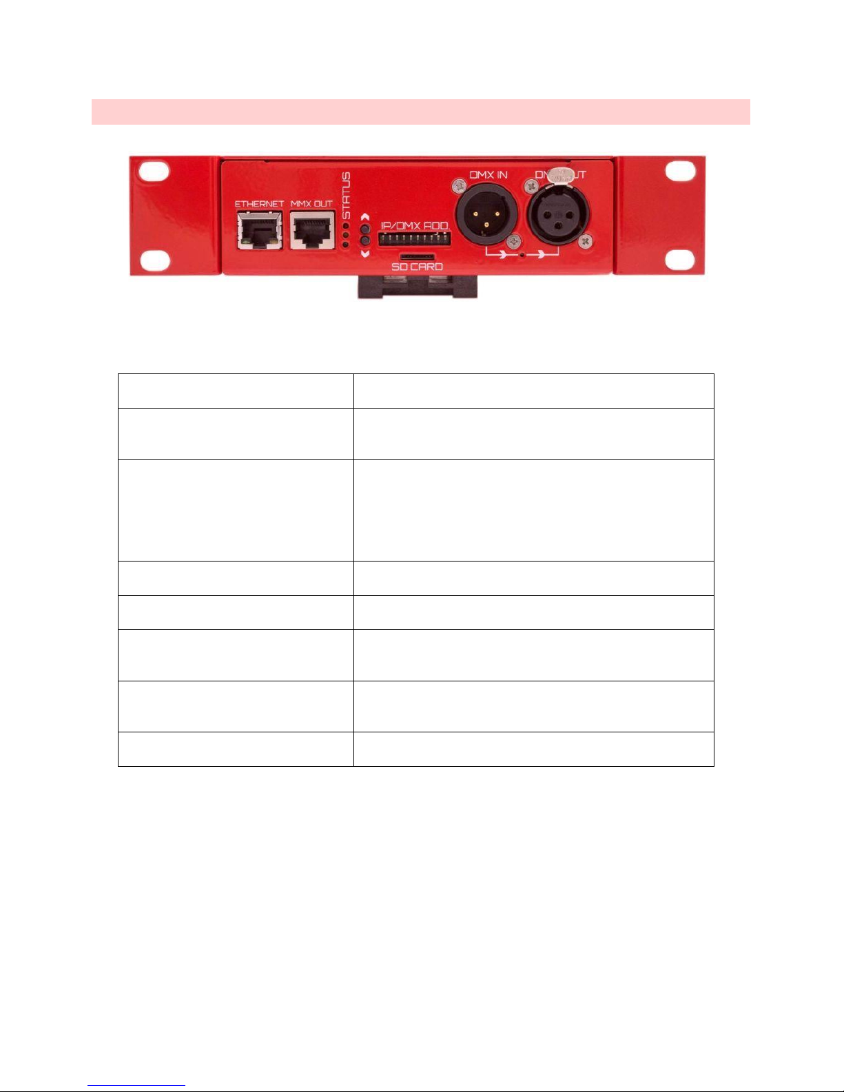
FRONT CONNE C T ORS
LEC3 front connectors
Ethernet
To control Ethernet board using LSS software you have to
connect your PC with Ethernet board using Ethernet cable.
MMX OUT - Distributor output (MMX
signal)
Output to following distributor. You can use more distributors
from one Ethernet board - you’ll get more LED-strip outputs.
Status
Three LEDs which show device status:
➢ Green – power is on
➢ Yellow – DMX or ArtNet is present (fast blink for DMX,
slow blink for ArtNet)
➢ Red – if on, LSS software is connected to the device
over Ethernet
Buttons
Allows you to select file to play in auto play mode and also to
run test patterns (in case the SD card is not inserted).
IP/DMX Add.
DIP switch allows you to set IP and DMX address. In auto-play
mode can be used to set animation to play.
SD-card
FAT32 micro SD-card for storing LED videos/animations. You
can trigger them using DMX, ArtNet or use them in auto play
mode.
DMX In/Out
You can use DMX In/Out to control LEC3 or LSS software. DMX
out can work in through or output mode (it’s a bit more
advanced comparing to standard DMX).
DMX LED
Indicates, whether the DMX is in though mode (typically in DMX
control mode).
Page 13
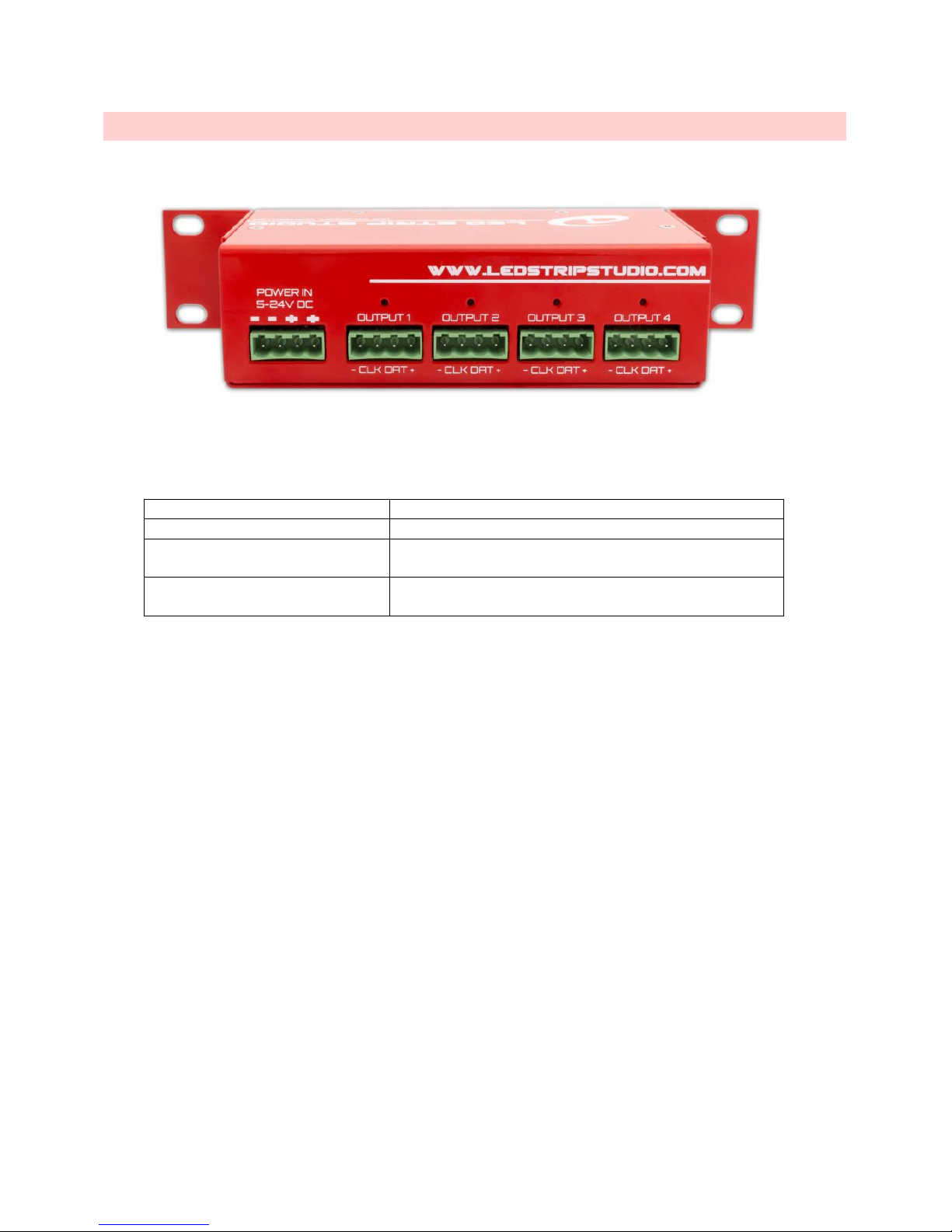
REAR CONNEC T O R S
LEC3 rear connectors
Power in 5-24V DC
Power connector for power source
Output 1 - 4
Powered SPI output for LED strips.
Output LED 1 - 4
Output status indicator – flashes when SPI signal is being sent
out.
DMX LED
In case the DMX Through is enabled (typically in DMX mode),
this LED is on.
LEC3 already contains one LSS Distributor with address 0. That’s why you can directly connect LED strips to LEC3.
Page 14
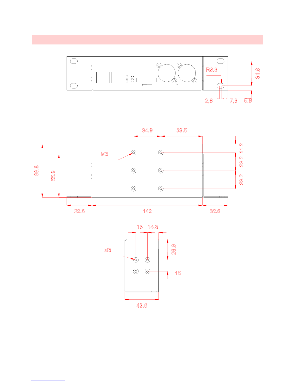
LEC3 DIMENS I O N S
Page 15
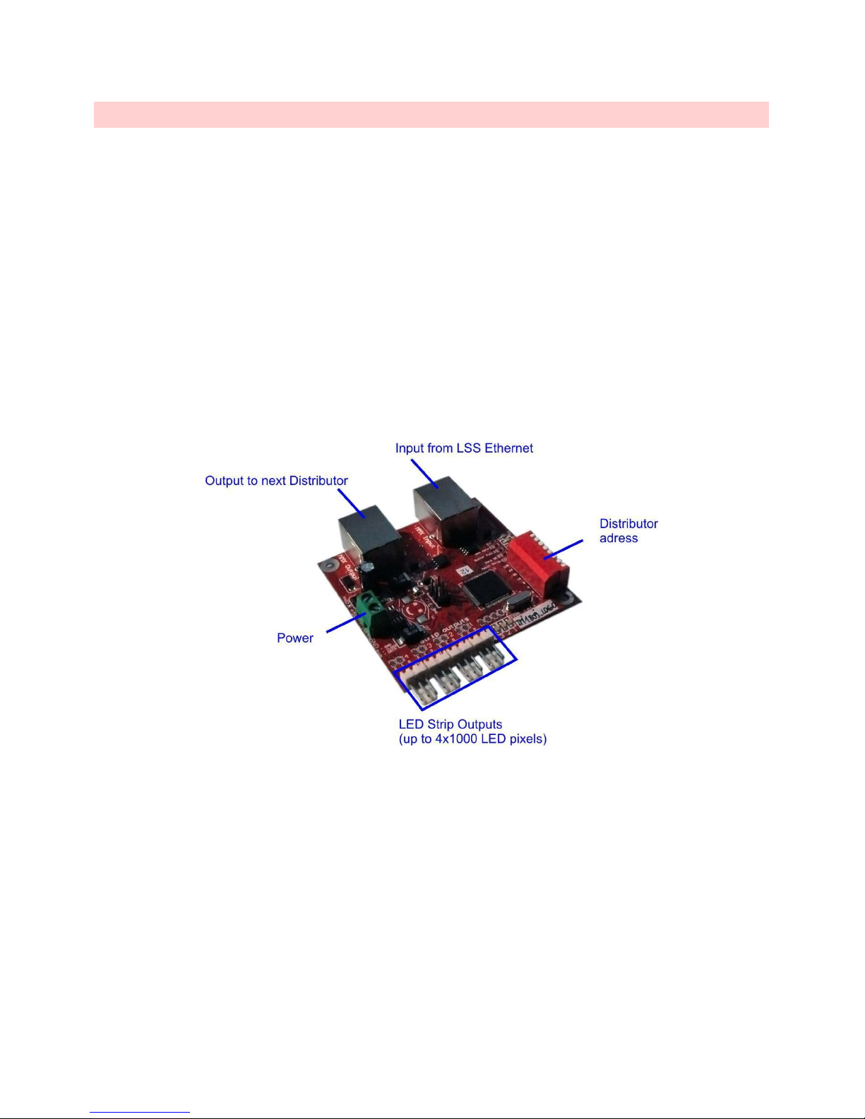
DISTRIBUTOR B O ARD
LSS Distributor is additional board, which receives signal from LEC3 Ethernet. It is used to control additional 4096
LEDs. To connect LEC3 Ethernet with LSS Distributor you can use standard Ethernet CAT-5 cable. Every distributor
has its own address set by DIP switch. Please don’t use address 0 (all switches off). Distributor 0 is already
integrated into LSS Ethernet.
LSS system now supports up to 32 distributors, thus the maximal address is 32. But the total number of digital LEDs
used for one LEC3 is 8192. It’s good to use more distributors in case you need to have longer distances between
more digital LED sections (e.g. two LED screens, 50m far away from each other).
Note 1.: The distributor is not powered, you need to use separate power source for your digital LED strips or digital
pixels.
Note 2.: Distributor’s Ethernet input uses special kind of signal (called MMX). It’s not standard TCP/IP! Ethernet
connector is used to provide convenient installation.
LSS Distributor board
Page 16
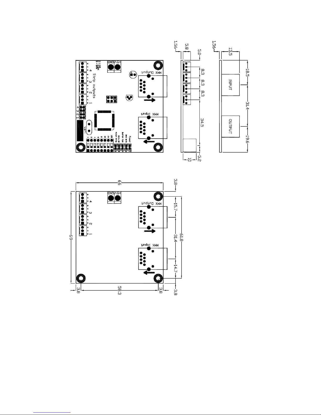
Distributor board dimensions and screw holes
Page 17
SAMPLE LE C 3 ETHERNET/ L S S DISTRI B U TOR CONFIG UR A TIONS
This is sample configuration of LSS controllers we recommend according number of LEDs used:
Number of LED pixels
Total meters for 42 LEDs/m
Recommended configuration
video strip
Up to 4096
95
1x LEC3
Up to 8192
190
1x LEC3, 1x LSS Distributor
Up to 12288
285
2x LEC3, 1x LSS Distributor
Up to 16384
380
2x LEC3, 2x LSS Distributor
Up to 20480
475
3x LEC3, 2x LSS Distributor
Up to 24576
570
3x LEC3, 3x LSS Distributor
Up to 28672
665
4x LEC3, 3x LSS Distributor
Up to 32768
760
4x LEC3, 4x LSS Distributor
Up to 36864
855
5x LEC3, 4x LSS Distributor
Up to 40960
950
5x LEC3, 5x LSS Distributor
Up to 45056
1045
6x LEC3, 5x LSS Distributor
Up to 49152
1140
6x LEC3, 6x LSS Distributor
Up to 52248
1235
7x LEC3, 6x LSS Distributor
Of course, sometimes to save a lot of work and cables, it’s better to use more LEC3 Ethernets or LSS
Distributors. If you don’t know the best configuration for your project, please contact us – we’ll try to give you
the best recommendation.
We’ve tested the system for up to 52000 LED pixels and it was working fine. But if more LEDs are required, we
recommend using more controlling computers to maintain the fluency of animation. Also for installations with
more than 16000 LEDs it’s strongly recommended to use Intel i5 and better processor in your computer.
Page 18
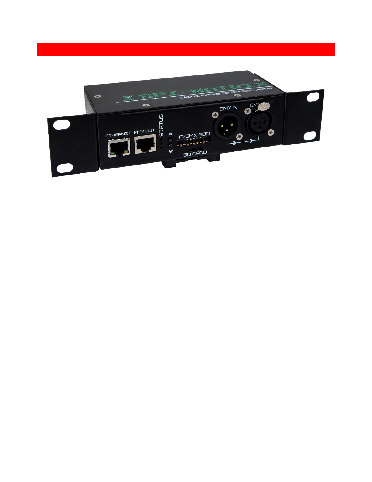
SPI-MATRIX
SPI-Matrix is pure ArtNet output device. It’s not supported by LED Strip Studio software. You can use it using following
software/hardware controllers:
• Madrix
• Chamsys
• MA-Grand
• Any other standard ArtNet controller
SPI-Matrix hardware is the same as LEC3 device, only the license key for LED Strip Studio software is not integrated.
Page 19
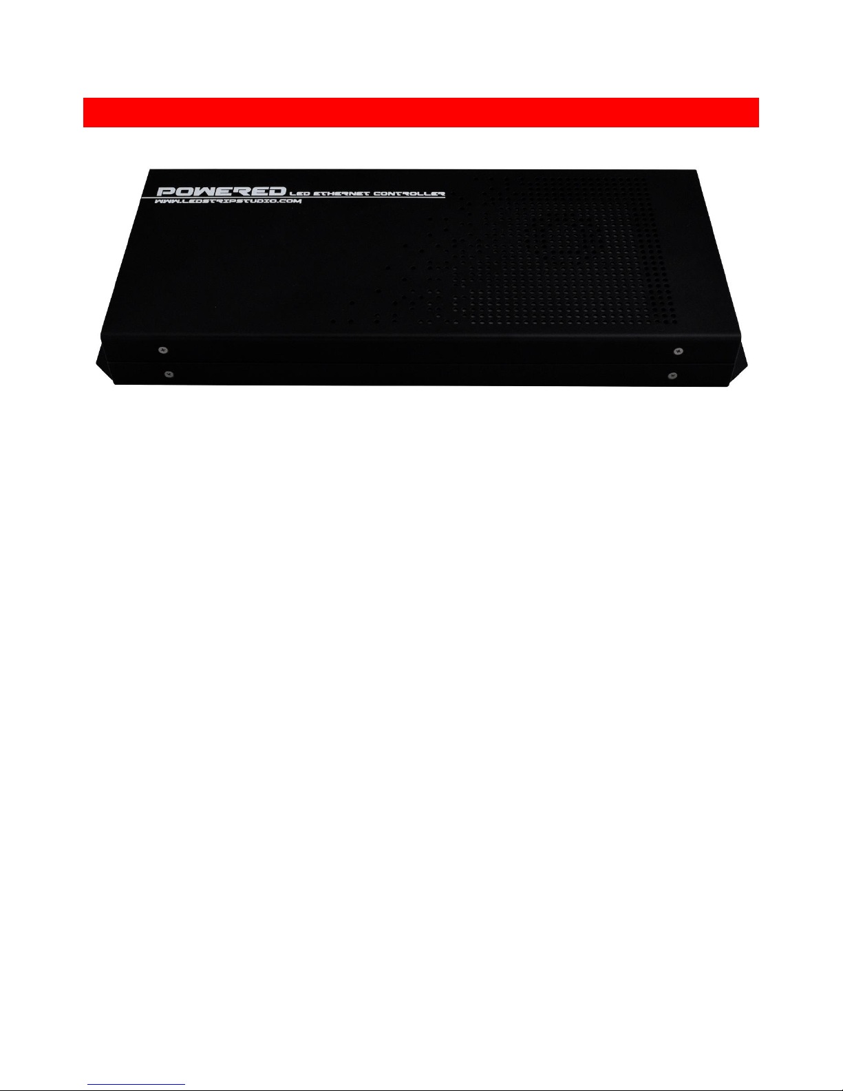
POWERED LED ETHERNET CONTROLLER
Powered LED Ethernet Controller is basically LEC3 device with integrated power source. PSU parameters are 320W,
5V, 60A. It’s ideal solution for rental businesses, which want to use digital led lights (strips, bars, pixels, …).
Page 20

LEC3 ETHERNET BOARD DMX CONTROL
It is possible to use LSS Ethernet also without the computer. You can play animations from SD-card and switch
between them using DMX. Here are DMX control channels:
1. Brightness – brightness of drawn image
2. Animation – choose animation from 0 to 255 (up to 256 animations).
3. Speed – speed of animation – default speed is 128.
4. Red (change color)
5. Green (change color)
6. Blue (change color)
It is also possible to control the LSS software using DMX. Please read software manual for more details.
Red, Green and Blue are used to change color of the image (not to control color channel intensity!).
Page 21
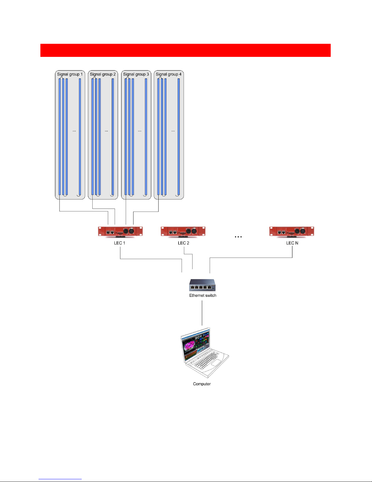
LED STRIP STUDIO – ETHERNET AND SIGNAL CONNECTION SCHEME WHEN USING LEC3
Typical signal connection of LED Strip Studio
You can use several LEC3 devices connected to Ethernet network to handle more than 4096 individual LED pixels
(even 50000 and more). Use standard Ethernet switch and Ethernet cables to do that.
Page 22
CONNECT I NG TM, WS, APA OR SK FAMILY LED STRIPS WITH LEC3
DIRECT CONNE C TION
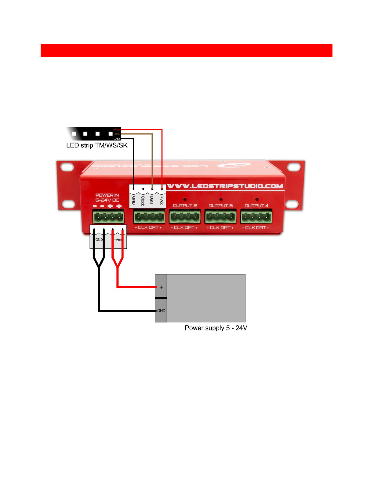
Following scheme shows how to connect SPI digital LEDs (TM, WS or SK family digital LEDs), power source and
LSS3:
Power source, TM/WS/SK LED strips and LEC3 board connection scheme
You can use 5-24V power supply depending on used digital strips or pixels. The power source can be connected
directly to LEC3. The SPI outputs are powered and LEC3 can handle up to 5A output power per output (thus you
can use up to 20A power source).
In case you use more power than 5A per output, LEC3 contains polyfuse (a.k.a. polyswitch or resettable fuse),
which will prevent destruction and lower the power (you’ll see, the brightness of your LEDs will be lower).
Page 23
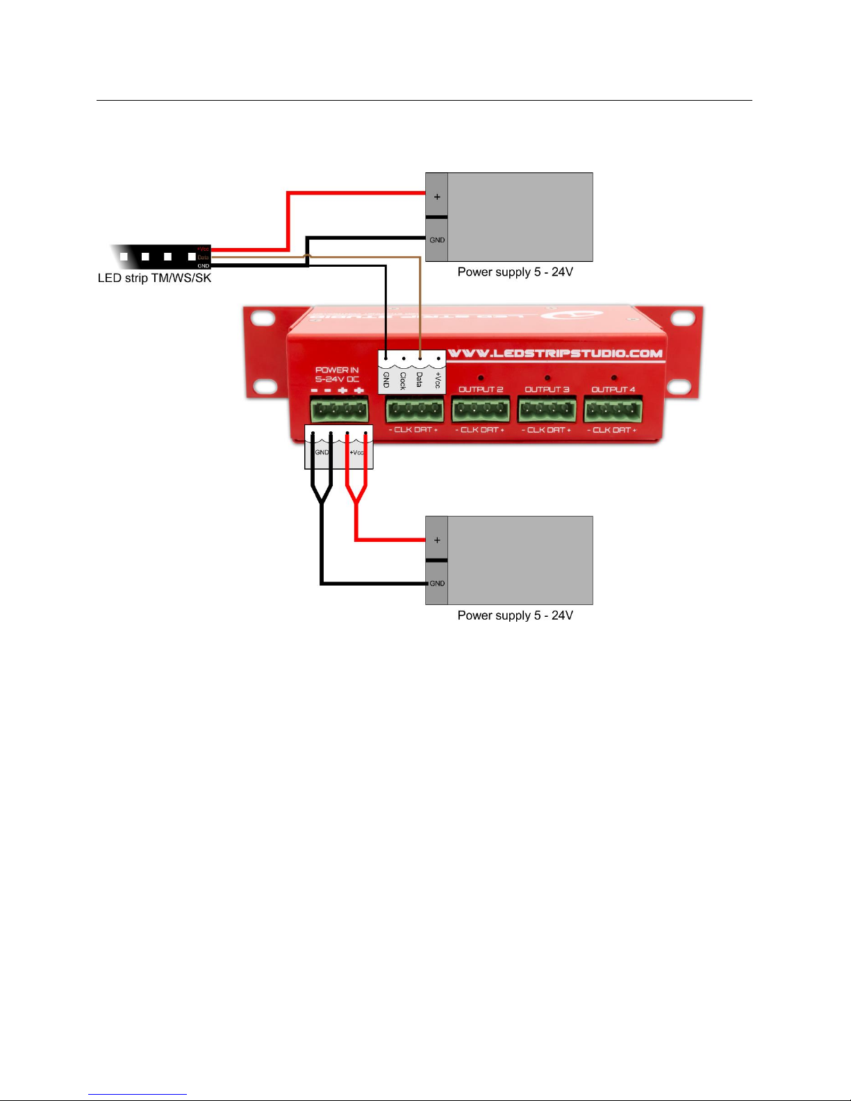
SEPARATE POWE R SUPPLI E S (MORE THAN 5A PER L E C3 OUTPUT)
In case you need more power per output than 5A, you can use separate power supply as on following scheme.
Using separate power supply with TM, WS or SK strips
If you notice, GND is connected to power source and to LEC3. But please connect only +Vcc of the LED strip with
LEC3. It might activate the polyfuse and disable signal output.
Notes:
• You need to connect LED strip + and GND to power source.
• If the LED strip is longer than 3m (typically), we recommend wiring both ends to the power source to
prevent intensity loss. Intensity loss is caused by voltage drop.
• Clock Ethernet output is connected only when using e.g. WS2801 or APA102 chip-based LED strips.
• When more power supplies are used, you can simply connect them to LED strip (e.g. usually digital LED
strips require power boost every 5m to not lose brightness).
Page 24
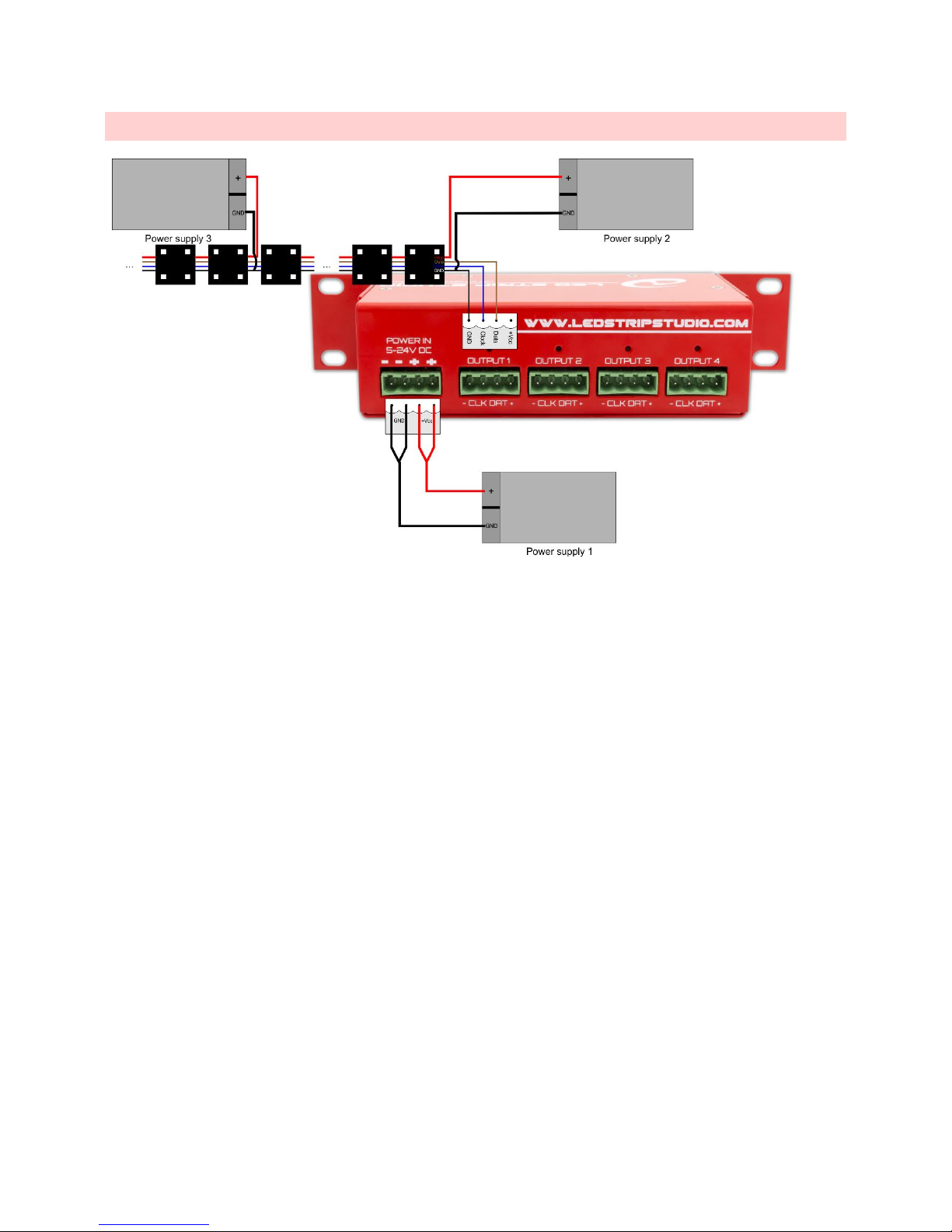
CONNECTING L E C3 WITH W S2801, WS280 3 L E D PI X ELS
Connecting LED Pixels and LEC3
Notes:
• Usually the LED Pixels use 12V power supply!
• LED Pixels usually use WS chips. You must connect also clock signal for the LED pixels! We usually use
blue line from LEC3/LSS Distributor and connect it to Clock on first pixel (usually the producers use yellow
color).
• The GND line from LEC3/Distributor must be connected to GND line from power source.
Power boost for LED pixels
One output of LEC3 can control up to 1024 pixels (1000 for LSS Distributor). But usually you can’t connect 1024
pixels from one side (intensity is lost). You must attach power from additional power source after few pixels.
Don’t connect the +12V to next segment!
The same trick can be used for LED strips as well.
Page 25
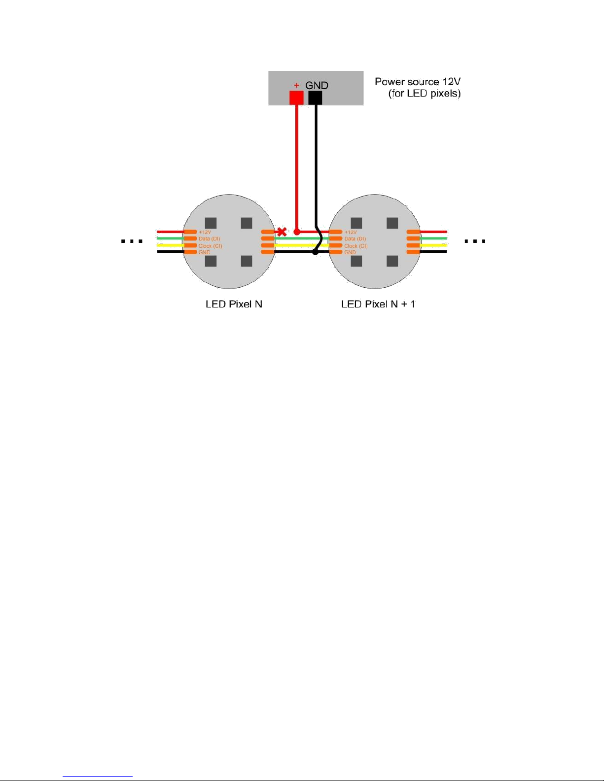
Pixel power boost
Page 26
DETAILED CA B L E -CONNECTIO N FOR LED ST R I PS
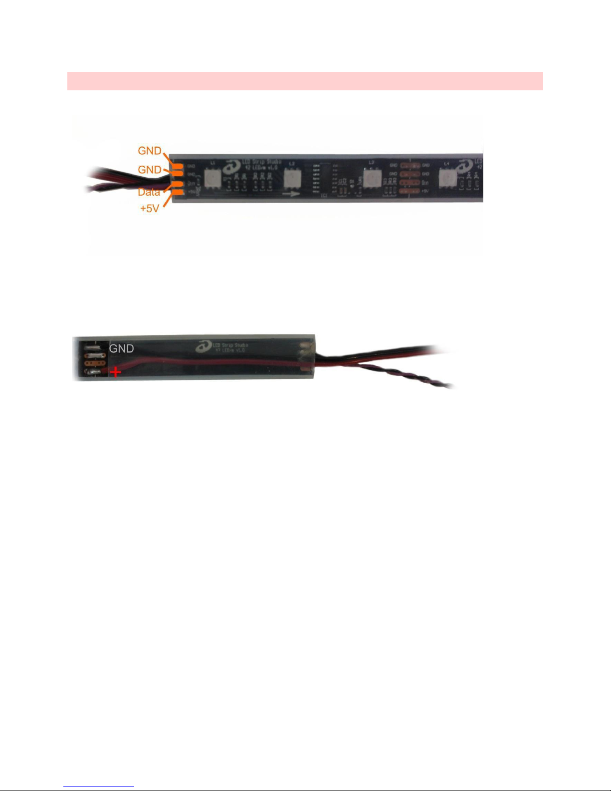
There are two GND (ground) pins, one Data and one +5V pin on LSS TM1809 LED strips:
Strip connection at the top
Recommended strip connection at the bottom
If you notice, we use a little trick here – it’s better to connect power-source cables to 2nd segment. There is a
simple reason why – it’s more solid and it’s harder to tear the cables from the strip. But please don’t use this
trick with Data – you must connect data cable to 1st segment!
Page 27
RECOMMENDED WIRE TYPES
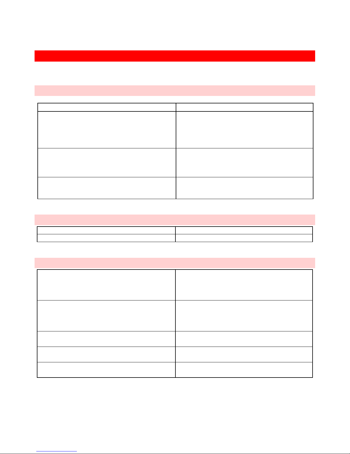
Every installation requires signal and power cables.
SIGNAL CABL E S
Cable type
Where to use
FTP Ethernet cable CAT.5E
• PC to LSS Ethernet
• LSS Ethernet to LSS Distributor
• LSS Distributor to LSS Distributor
• sometimes possible also for LSS Distributor
to LED strip
LiY 0.14mm2 black + brown twisted
• LSS Distributor to LED strip
• LED strip to LED strip
Don’t use for signal distance longer than 5m!
Only for use in non-heavy EMI interfered environment.
LIYCY 2x0.14mm2
• LSS Distributor to LED strip
• LED strip to LED strip
Use for longer distance approx. up to 15m.
POWER CABLE S 1 1 0-230 V
Cable
Where to use
230V AC, H05RR-F - 3Cx1,5 / 3Cx2,5
110V-230V power distribution / power supplies
POWER CABLE S 5 V DC
H05V-K 0.5mm2 black + red
5V distribution for short strips (max 5m) for short
distance from PS* (max 2m), also good to trace
parallel with strip to decrease losses in strip when
strip is longer (3m+)
H05V-K 1.0mm2 black + red
5V distribution for strips (max 10m) for short
distance from PS (max 2.5m), also good to trace
parallel with strip to decrease losses in strip when
strip is longer (5m+)
H05V-K 1.5mm2 black + red
5V distribution for strips (max 15m) for short
distance from PS (max 3m)
H05V-K 4.0mm2 black + red
5V distribution for strips (max 40m) for short
distance from PS (max 4m)
H05V-K 6.0mm2 black + red
5V distribution for strips (max 60m) for longer
distance from PS
*PS = power supply
Page 28

To convert mm2 to AWG please refer to this table:
American Wire Gauge
Diameter
Diameter
Cross Sectional Area
(AWG)
(inches)
(mm)
(mm2)
0000
0.46
11.68
107.16
000
0.4096
10.40
84.97
00
0.3648
9.27
67.40
0
0.3249
8.25
53.46
1
0.2893
7.35
42.39
2
0.2576
6.54
33.61
3
0.2294
5.83
26.65
4
0.2043
5.19
21.14
5
0.1819
4.62
16.76
6
0.162
4.11
13.29
7
0.1443
3.67
10.55
8
0.1285
3.26
8.36
9
0.1144
2.91
6.63
10
0.1019
2.59
5.26
11
0.0907
2.30
4.17
12
0.0808
2.05
3.31
13
0.072
1.83
2.63
14
0.0641
1.63
2.08
15
0.0571
1.45
1.65
16
0.0508
1.29
1.31
17
0.0453
1.15
1.04
18
0.0403
1.02
0.82
19
0.0359
0.91
0.65
20
0.032
0.81
0.52
21
0.0285
0.72
0.41
22
0.0254
0.65
0.33
23
0.0226
0.57
0.26
24
0.0201
0.51
0.20
25
0.0179
0.45
0.16
26
0.0159
0.40
0.13
Page 29

LEC3 CONTROL MODES
You can control LEC3 in 4 different ways:
• Ethernet mode - using LED Strip Studio software over Ethernet
• ArtNet mode – using any ArtNet controller (console or software)
• DMX mode – using any kind of DMX controller
• Stand-alone mode – you can store several LED animations on your SD card and play them without any
ArtNet/DMX controller or computer.
• Testing – great to use different test your installation using standard test patterns.
There is one more mode, which can be used over web configuration – Test mode.
ETHERNET MO D E
The most common usage of the LEC3 is to use it as LED output for LED Strip Studio software. The main benefit is the
real-time control – you can drag and drop and play video, generate nice LED effects or even create complete LED
show synchronized with music in the timeline feature of LED Strip Studio.
This is highest priority mode – it automatically stops ArtNet, DMX or auto-play mode.
The DMX IN signal is sent back to LED Strip Studio software. You can use it to control LED Strip Studio software over
DMX. DMX OUT is used by LED Strip Studio software (typically to control analog LED strips). DMX OUT is not DMX
through in this mode!
There is a complete manual available for LED Strip Studio, please check it to find out more information about it.
ARTNET MODE
This mode is automatically activated if there is ArtNet signal coming over Ethernet to LEC3 device (yellow LED is
flashing) and LED Strip Studio software is *not* connected to LEC3.
There are two ways you can use LEC3 in ArtNet mode:
• Pixel
• SD-Card
You can switch between these two modes in LEC3 Web Configuration.
ARTNET PIXEL M O DE
This is great way to use LEC3 as a direct digital pixel output for your favorite ArtNet software (e.g. Madrix,
MadMapper, MA Grand lightning consoles, …). In Pixel mode you control every pixel directly using 3 DMX channels
(Red, Green and Blue).
One ArtNet universe allows you to control up to 170 individual LED pixels (512 / 3 = 170). But in LEC3 Web
Configuration you can define up to 7 universes, which will control all 1024 LEDs of one LEC3 SPI output. Each
output can use different ArtNet universes, so you’ll be able to control all 4096 individual LED pixels over ArtNet.
For every SPI output you can set first universe and it automatically uses following up to 6 universes to control all
1024 LEDs (you can use lower LED count though).
Page 30
ARTNET SD - C A R D MODE
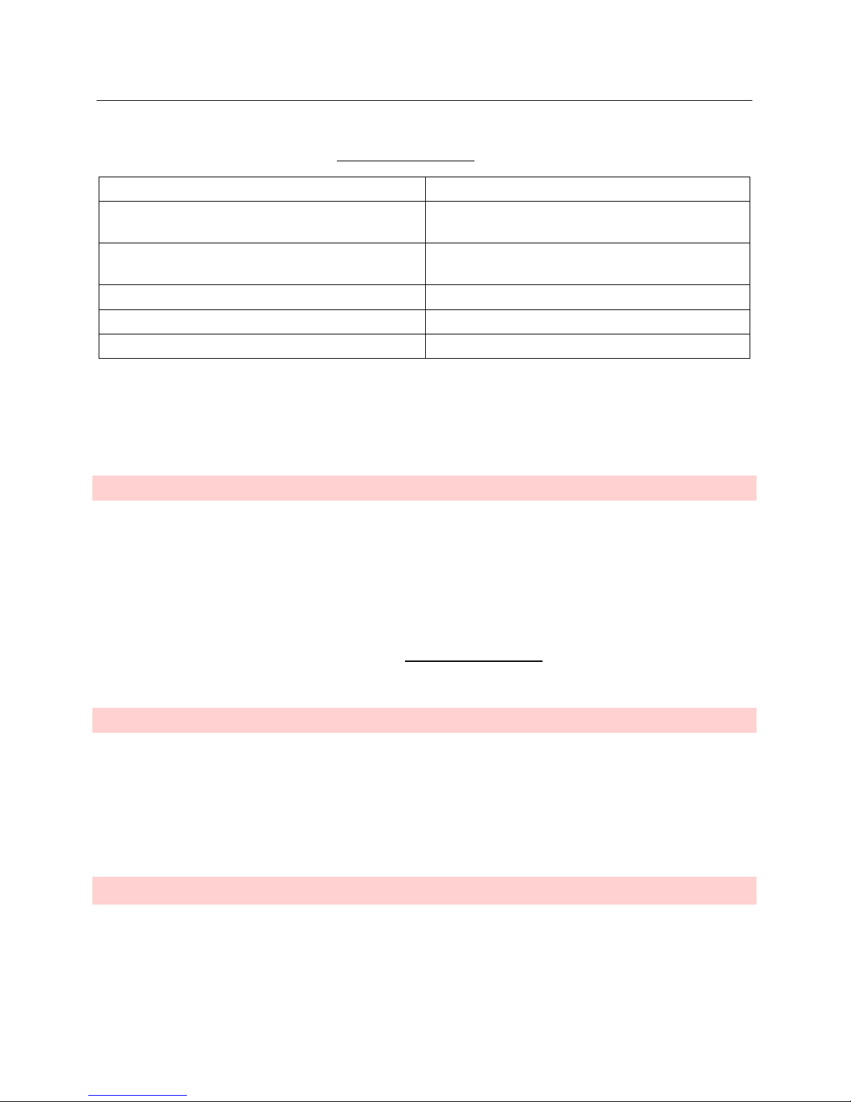
In this mode you can trigger animations stored on SD card (exported from LED Strip Studio software). You can set
what Universe and DMX address to use in LEC3 Web Configuration. LED Strip Studio uses following DMX channels:
1. Brightness
Animation brightness
2. Animation
You can select animation 1 to 255 using this channel. 0 is
empty.
3. Speed
Speed of animation. 0 is pause, 128 is default speed of
video or animation. 255 is 4x faster than default speed.
4. Red
*
5. Green
*
6. Blue
*
*Last 3 channels set the color of all pixels (while maintaining intensity levels). It’s not intensity of each channel!
You can store up to 255 different animations on SD card. They can be complete shows (10 and more minutes long).
Using this mode you can switch between them to do live light LED show.
DMX MODE
This mode is automatically activated when there is DMX signal connected to DMX input and there’s no LED Strip
Studio software or some ArtNet controller connected to the device.
Again, you can use LEC3 in two ways in DMX mode:
• Pixel
• SD-Card
The meaning of these modes is the same as in ArtNet mode. The only difference is, in pixel mode you can control
only up to 170 LEDs. You can configure both modes in LEC3 Web Configuration.
AUTO-PLAY M O DE
Lowest priority mode. It allows you to play animations stored on SD-card (exported from LED Strip Studio
software). By default LEC3 plays animation selected by DIP switch or defined in Web configuraion. But you can use
buttons to switch between the animations.
Autoplay mode is also able to play DMX files (*.ldm) stored on SD card along with the digital animation files (*.lnt).
This makes LEC3 a complete stand alone digital and analog LED controller.
TE STING MO D E
In case you change settings in the web configuration, you can display several test patterns on the SPI outputs. It’s
practical to e.g. set correct order of the RGB color channels.
You can also activate test mode by removing SD card and using device buttons to switch the different test pattern.
Page 31
DMX OUT
DMX Out can be in two different modes – Out and Through.
Through
This mode of DMX OUT is active only in case you use LEC3 in DMX mode. Data from DMX in is
automatically send to DMX out (similar to any other kind of DMX light).
Out
This mode means, the LEC3 device is generating the DMX signal. The signal can be generated from
different sources:
• In Ethernet mode, LSS software generates DMX out data.
• In Art-Net mode you can set one universe to be sent out as standard DMX512 signal.
• In case you’ve exported also DMX file on the SD card (*.ldm), in Autoplay mode the DMX
is generated from this file.
Page 32
LEC3 WEB CONFIGURATION
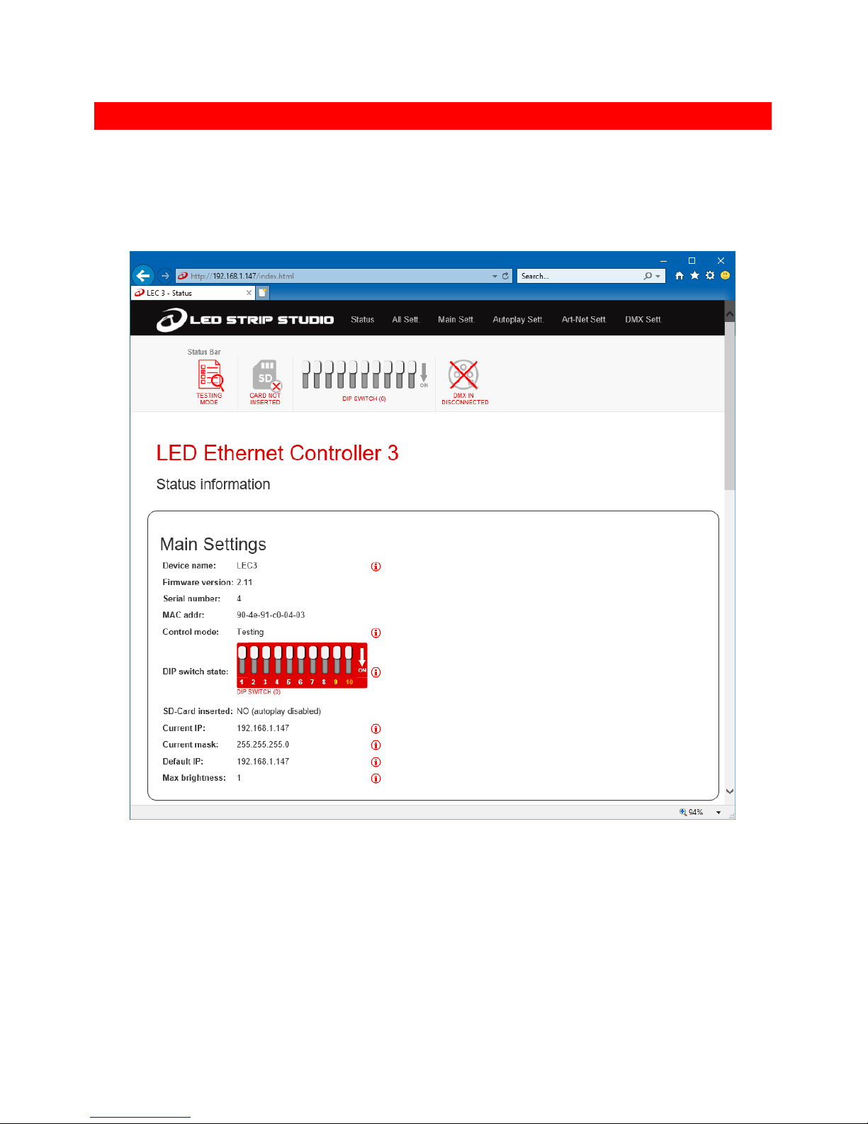
Web configuration allows you to set all important parameters of LEC3 even using your mobile phone (but you can
also use any Windows or Mac computer).
To access web configuration you must type your device IP address into Internet Explorer, Chrome, Safari or any
other favorite web browser. E.g. if your device IP address is set to 192.168.1.147, just type “192.168.1.147” into
your web browser address:
LEC3 web configuration
Note: Make sure your computer IP address (or your IP router DHCP) is in 192.168.1. address range to be able to
access the web configuration.
Page 33
MAIN MENU
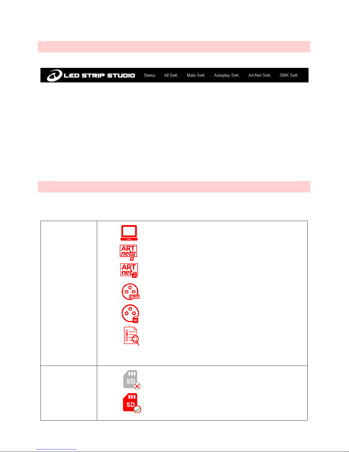
You can select following options in menu:
• Status – displays status of the device
• All Sett. – displays all settings of the device.
• Main Sett., Autoplay Sett., Art-Net Sett., DMX Sett. – will enable you to display just settings for desired
section of the All Sett.
All settings sections can be accessed only after you login. Default login for LEC3 device is:
• User name: admin
• Password: admin
STATUS BAR
You can see following information in the top status bar of web configuration page.
Mode
• Ethernet mode
• Art-Net RGB pixel mode
• Art-Net SD-card mode
• DMX pixel mode
• DMX SD-card mode
• Testing mode
SD-card status
• SD-card is not inserted
• SD-card is ready to be used
Page 34
DIP switch
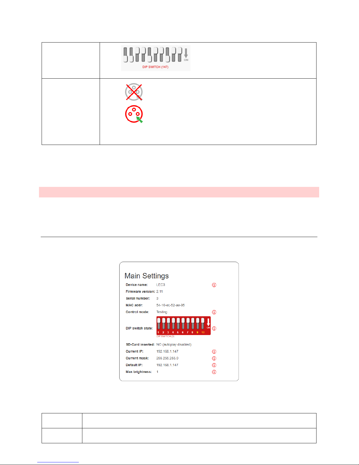
• Shows current status of DIP switch
DMX in status
• DMX in is not connected
• DMX in is connected and receiving data
The status bar is “live” – you can see all the changes immediately.
STATUS
First screen you’ll see after you open LEC3 configuration is the Status screen. There are several sections of the
status.
MAIN SETTIN G S
Contains basic settings of the LEC3 device.
Main settings display basic settings of the device
Device name
Name of the device. You can change this in the settings.
Firmware
version
Shows current firmware version. You can update firmware version to obtain latest features and
improvements.
Page 35
Serial number
Serial number of the device.
MAC addr
MAC address of the device.
Control mode
Shows current control mode. See the LEC3 control modes for details.
DIP switch state
Shows the current DIP switch state.
SD-Card
inserted
Shows whether SD card is inserted into the device (Yes/No).
Current IP
Displays current IP address of the device. This can be changed using DIP switch or in the
configuration.
Current mask
Displays current IP address mask. This can be changed in the configuration.
Default IP
Displays default IP address of the device. Default IP address is used in case the DIP switch is set to
0.
Max brightness
Current maximal brightness of the SPI outputs.
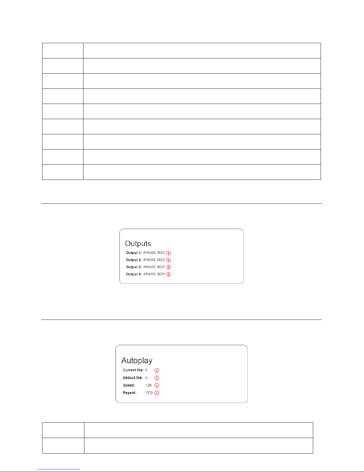
OUTPUTS
Here you can find information about what type of LED IC is used for every output of the device.
Selected type of used LED IC
AUTOPLAY
In the auto play section, you can find information about auto play settings.
Current file
In case the auto play is active, here you can see, what file is being played. If this is 0, file is not
being played.
Default file
Here you can see, what file will be played after the device is started. This can be changed in
settings. This setting is used only in case the DIP switch is set to 0!
Page 36
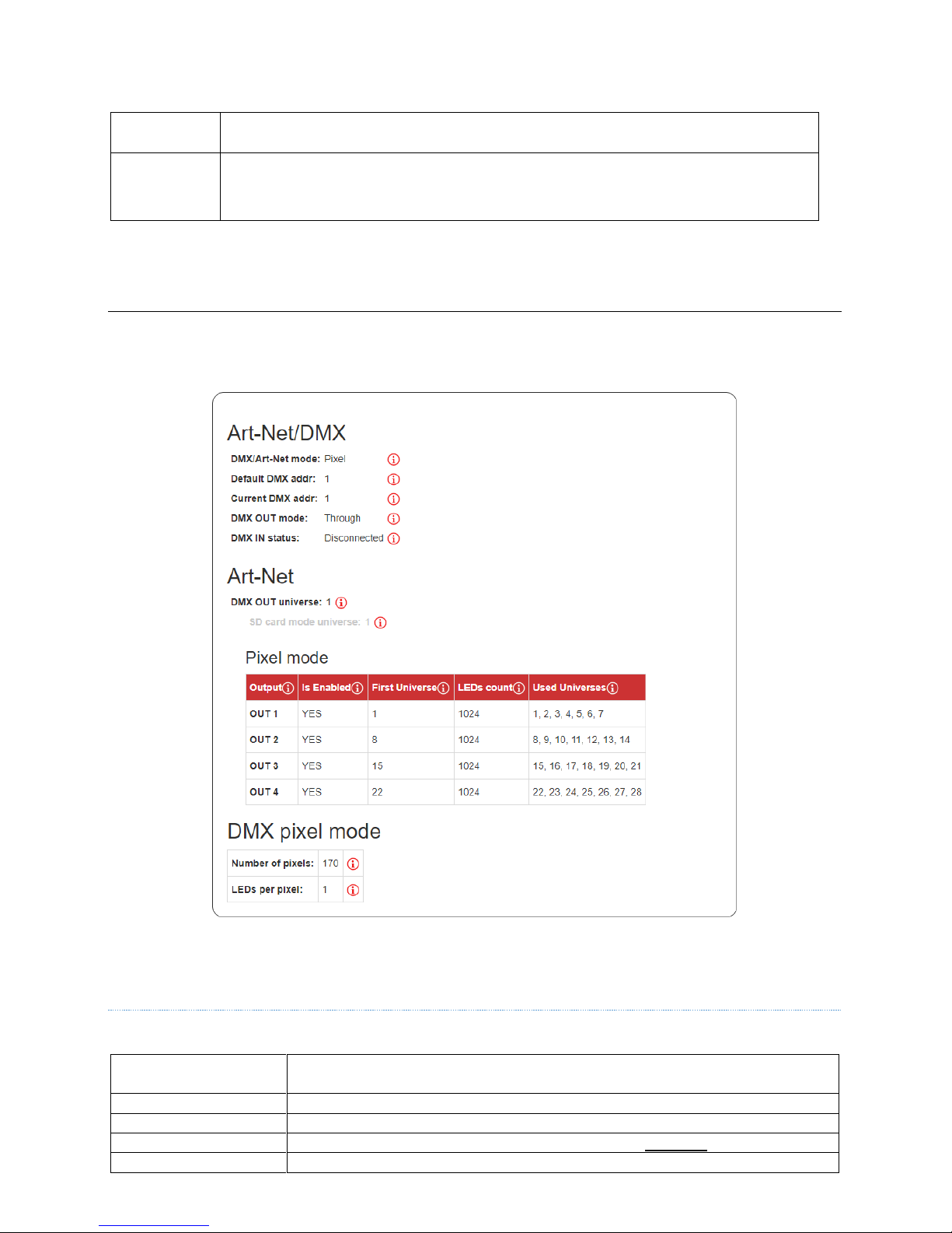
Speed
Serial number of the device.
Repeat
If this is on, file is repeated. This setting is also used for DMX SD-card and Art-Net SD-card
mode.
ART-N ET/DMX
This section shows settings related to Art-Net and DMX.
Art-Net and DMX settings
ART-NET/DMX
DMX/Art-Net mode
You can use LEC3 in Pixel or SD Card mode over Art-Net and DMX. Find more
information about it in ArtNet mode.
Default DMX addr
Default DMX address in case DIP switch is set to 0.
Current DMX addr
Displays current DMX address.
DMX OUT mode
Can be DMX Out and DMX Through. See more details in DMX Out.
DMX IN status
Indicates whether valid DMX512 signal is connected to LEC3 device.
Page 37
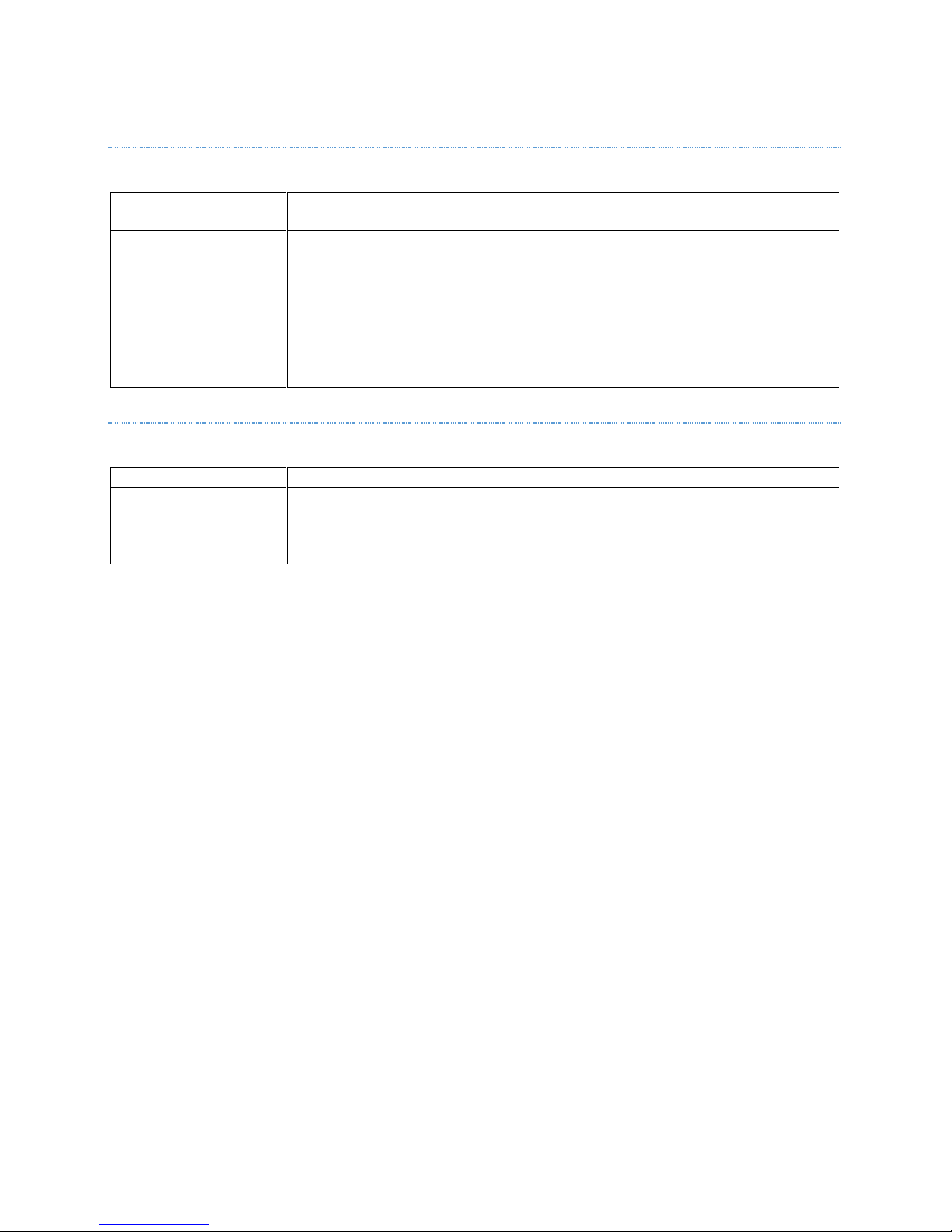
ART-NET
DMX OUT universe
You can select one universe of incoming Art-Net universes to be sent out as DMX512
signal out of the LEC3 device.
Pixel mode
Display current settings of outputs for Art-Net.
• Out1-Out4 – one of the 4 outputs
• Is Enabled – indicates, whether output is enabled
• First Universe – to use all 1024 LEDs you have to combine several universes
from incoming Art-Net signal. This shows, which universe is the first one to be
used.
• LEDs count – how many LEDs are being used for selected output.
• Used Universes – list of all used universes by the output.
DMX PIXEL MODE
Number of pixels
Number of used pixels for DMX output (1 to 170)
LEDs per pixel
One incoming RGB pixel (3 DMX channels) can be used several times on SPI output.
This number sets, how many LED pixels on SPI output are controlled using 3 incoming
RGB channels (e.g. if you set this to 4, four LEDs will have same color / will work as one
LED pixel).
Page 38
ALL SETT.
Display all the settings of the LEC3 device. In case you want to display just some of Main, Autoplay, Art-Net or DMX
settings, just click some of the link in the main top menu. This is the list of all the sections with explanation.
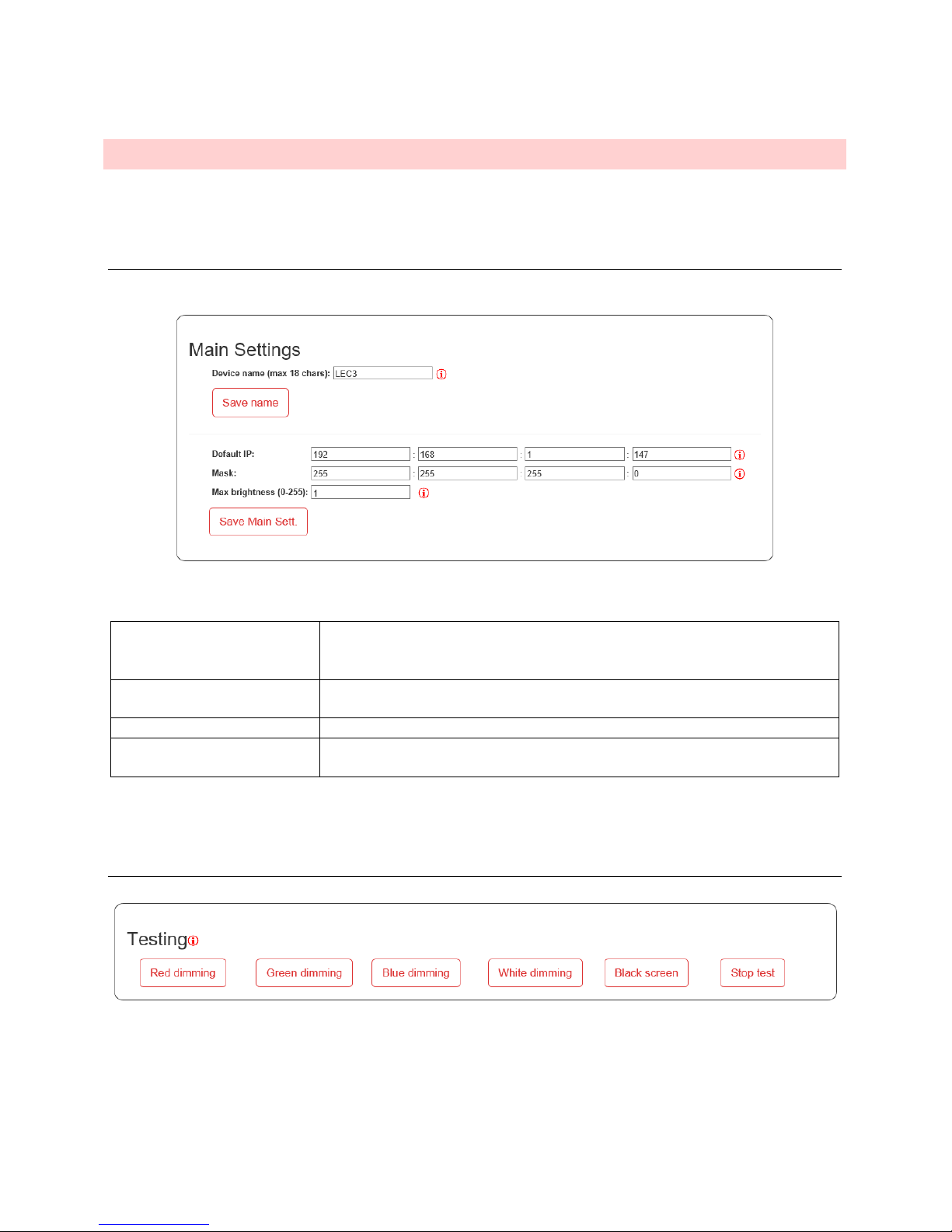
MAIN SETTIN G S
Contains basic settings of the LEC3 device.
Device name (max 18 chars)
You can set device name for better orientation in case you use multiple LEC3
devices in your installation. You have to press Save name to save the setting after
you change it.
Default IP
In case the DIP switch is set to 0, this is the device IP address, which will be used
in Local Area Network.
Mask
IP Address mask can be set here.
Max brightness (0-255)
Maximal brightness of all output for all modes. This is practical in case you want
to save your LED life by lowering maximal brightness for the users.
Don’t for get to press Save Main Sett. or Save name after you change some of the setting!
TE STING
This allows you to display several test patterns on your LEC3 SPI output. It’s practical to e.g. set the order of the
RGB channels or type of the used LED strip (LED IC). Don’t forget to press Stop Test after you finish to make sure,
the device will stop displaying test pattern!
Page 39
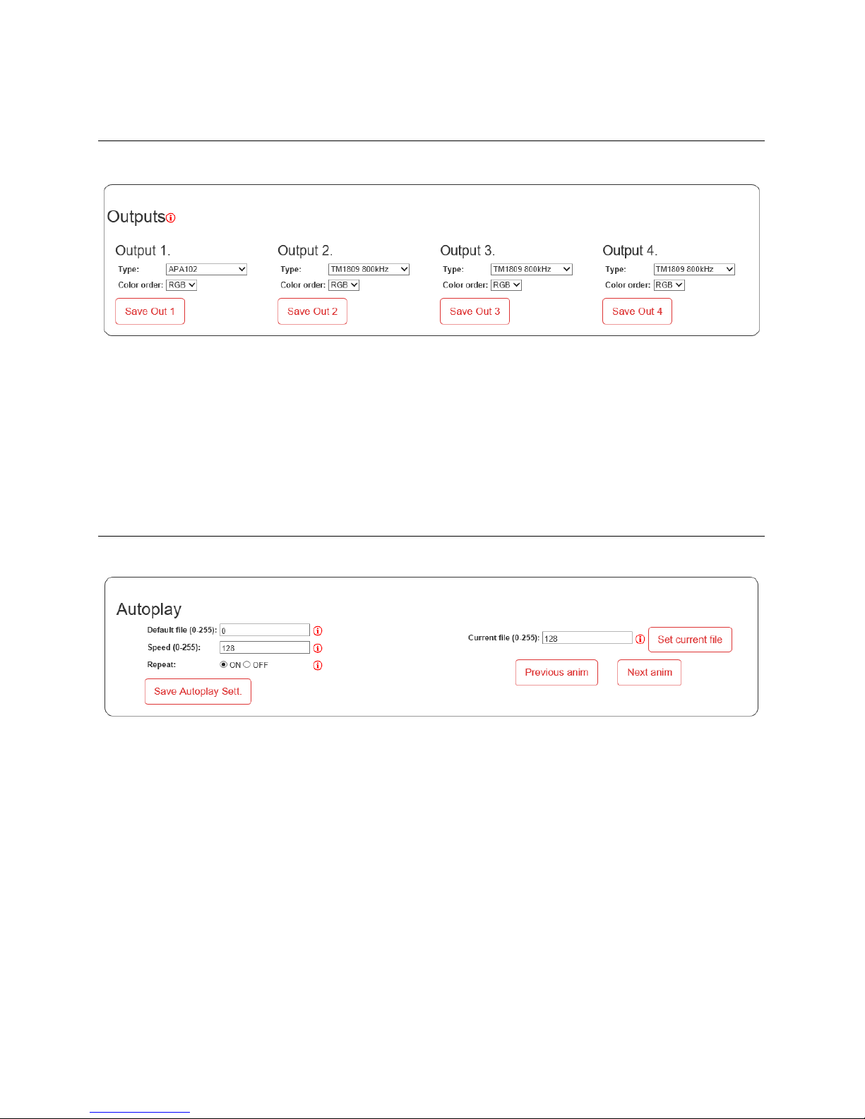
OUTPUTS
Here you can define type and color order of every SPI output.
• Type – type of the used LED control IC (chip), e.g. TM1809, WS2811, APA102, …
• Color order – order of the RGB channels.
All these settings are used in Art-Net, DMX and Autoplay modes. In case you control LEC3 from LSS software, you
define these settings in the LED Strip Studio workspace.
AUTOPLAY
These settings allow you to define how the device is working in auto play mode.
• Default file (0-255) – allows you to select which one of the 1 to 255 files will be used to play automatically
after the device is started. In case it’s 0, no file is played after start (default setting).
• Speed (0-255) – speed of the default file. 0 = stop, 128 = 100% speed, 255 = 400% speed.
• Repeat On/Off – sets repeat of the default file to On or Off. This setting is also used in Art-Net SD-card
and DMX SD-card mode.
• Current file (0-255) – allows you to preview some of the files without the need of DMX signal or selecting
it manually using LEC3 device buttons. Don’t forget to press Set current file to display the file. You can
also use device buttons to change current file.
In case you change some of the settings, press Save Autoplay Sett. to store the settings.
Page 40
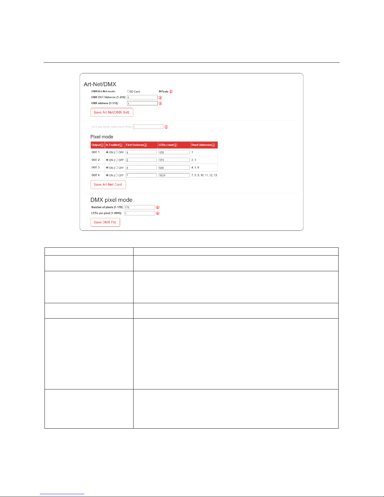
ART-NET/DMX
DMX/Art-Net mode
Allows you to select between SD-card or Pixel mode for Art-Net and DMX
DMX OUT Universe (1-256)
One universe of the incoming Art-Net universes can be used send out from LEC3
device as standard DMX512 signal. You can define which one it’ll be.
DMX address (1-512)
DMX address. This setting is used in 3 different cases:
• DMX input address for DMX in SD-card mode
• DMX input address for DMX in Pixel mode
• DMX address for Art-Net in Art-Net SD-card mode
SD-Card mode universe (1-256)
In case you use LEC3 in Art-Net SD-card mode, here you can define which
universe is used. This is disabled in case you use Art-Net/DMX pixel mode.
Pixel mode
Settings for all the SPI outputs:
• Is Enabled – you can enable or disable output here
• First Universe – defines which universe is used as first universe for
given output.
• LEDs count – number of LEDs per given output.
• Used universes – here you can see what universes are used for given
output.
Don’t forget to press Save Art-Net Conf. to save the settings.
This setting is disabled in case you use Art-Net/DMX SD-card mode.
DMX pixel mode
This setting is related only to DMX512 input:
• Number of pixels (1-170) – how many pixels are used of the incoming
DMX in signal
• LEDs per pixel (1-4096) – you can use seveal LED pixels per one RGB
pixel from incoming DMX in
Page 41

ACCOUNT SET TI N GS
You can change your current password. Default name and password is admin/admin. You can reset password by
resetting device to default state (by holding Up button at the device power up for 5 seconds).
Page 42

NOTES:
 Loading...