

Page 1
INSTALLATION INSTRUCTIONS
DL 4inch
LED Retrofit Down Light
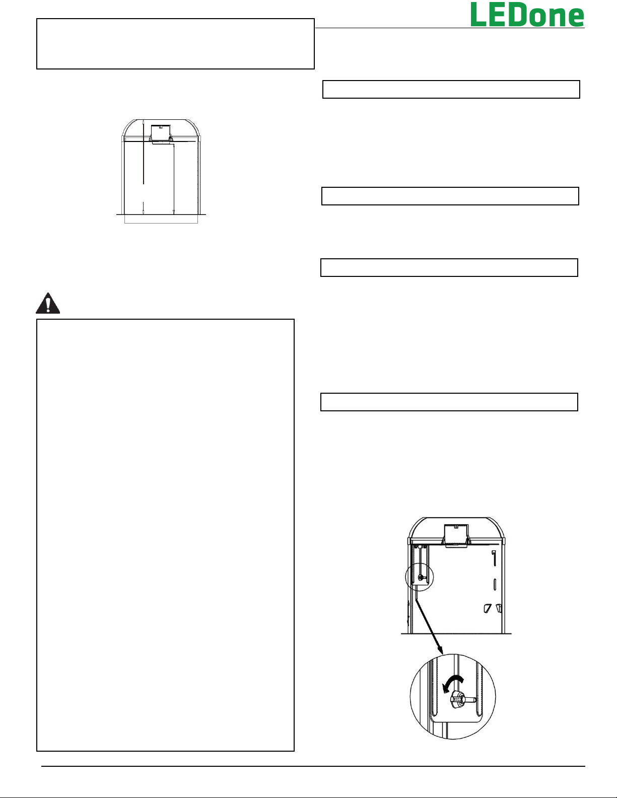
5. 5"
Min5“
(127mm)
(140mm)
Min 4 “
(101.6mm)
LAMP COMPARTMENT DIMENSIONS Min. 4-inch
(101.6mm) DIA X 5 inch (127mm) H for 4-inch
models.
CAUTION
IMPORTANT SAFEGUARDS
When using electrical equipment, basic safety precautions
should always be followed including the following.
READ AND FOLLOW ALL SAFETY
INSTRUCTIONS
1. DANGER- Risk of shock- Disconnect power before installation.
2. WARNING – Risk of fire or electric shock. LED Retrofit Kit
installation requires knowledge of luminaires electrical systems.
If not qualified, do not attempt installation. Product must be
installed in accordance with NEC or your local electrical code.
If you are not familiar with these codes and requirements,
contact a qualified electrician.
3. Suitable for damp locations. For indoor use only.
4. Suitable for Type IC or NON-IC Luminaires.
5. Do not make or alter any open holes in an enclosure of
wiring or electrical components during kit installation.
6. WARNING – To prevent wiring damage or abrasion, do not
expose wires to the edge of sheet metal or any other
sharp objects.
7. WARNING: Not for emergency lighting.
8. Maximum 8 of 12 AWG through branch circuit conductor
suitable for 75°C permitted in box
9. WARNING: RISK OF FIRE OR ELECTRICAL SHOCK. Do
not alter, relocate, or remove wiring, lamp holders, power
supply, or any other electrical component.
10. WARNING - Risk of fire or electric shock. Install this kit
only in luminaires that have the construction features and
dimensions shown in the photographs and/or drawings
and where the input rating of the retrofit kit does not
exceed the input rating of the luminaire.
SAVE THESE INSTRUCTIONS FOR
FUTURE REFERENCE
2018-11-14
PACKAGING CONTENTS
• 4” retrofit downlight
• Installation instructions in English
INSTALLATION
1. Make sure the POWER IS TURNED OFF at the source to the
recessed can.
2. Remove existing trim and bulb revealing the existing recessed
sockets.
INCANDESCENT HOUSINGS
1. Unscrew the wing nut inside the can to detach the socket bracket
from the can. Disengage the socket from the socket bracket. See
Figure 1.
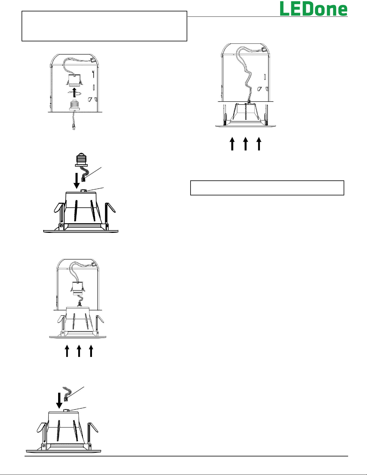
2. Thread the Socket Adapter into the socket. See Figure 2 on the
back page.
3. Plug the female connector of the retrofit trim onto the male
connector of the socket adapter assembly. See Figure 3 on the
back page.
4. Tuck all wires into the can and carefully push the retrofit trim
into can. See Figure 4 on the back page.
LED HOUSINGS
1. Plug the female connector of the retrofit trim onto the male
connector of the housing. See Figure 5 on the back page.
2. Tuck all wires into the can and carefully push the retrofit trim
into can. See Figure 6 on the back page.
FIGURE 1
Page 2
INSTALLATION INSTRUCTIONS
DL 4inch
LED Retrofit Down Light
FIGURE 2
FIGURE 3
Male Connector
Female Connector
Embedded On Back
Of Downlight
FIGURE 4
FIGURE 5
Male Connector
Female Connector
Embedded On Back
Of Downlight
2018-11-14
FIGURE 6
FCC NOTICE
CAUTION: Changes or modifications not expressly approved could
void your authority to use this equipment.
This device complies with part 15 of the FCC Rules. Operation is
subject to the following two conditions: (1) This device may not cause
harmful interference, and (2) this device must accept any interference
received, including interference that may cause undesired operation.
Changes or modifications not expressly approved could void
your authority to use this equipment.
This equipment has been tested and found to comply with the limits
for a Class B digital device, pursuant to part 15 of the FCC Rules.
These limits are designed to provide reasonable protection against
harmful interference in a residential installation. This equipment
generates, uses and can radiate radio frequency energy and, if not
installed and used in accordance with the instructions, may cause
harmful interference to radio communications. However, there is no
guarantee that interference will not occur in a particular installation.
If this equipment does cause harmful interference to radio or
television reception, which can be determined by turning the
equipment off and on, the user is encouraged to try to correct the
interference by one or more of the following measures:
—Reorient or relocate the receiving antenna.
—Increase the separation between the equipment and receiver. —
Connect the equipment into an outlet on a circuit different from that to
which the receiver is connected.
—Consult the dealer or an experienced radio/TV technician for help.
 Loading...