

LED Neon Flex Profile 11D, Vivid S 270, Dynamic White 270, Vivid S 270 Pixel, Vivid S 270 RGB User Manual

Version 4.0
Prole 11D User Manual
For Products: Vivid S 270, Vivid S 270 Pixel, Vivid S 270 RGB, Dynamic White 270
PLEASE READ THESE INSTRUCTIONS CAREFULLY BEFORE INSTALLATION.
INCORRECT INSTALLATION AND HANDLING CAN VOID YOUR WARRANTY.
Table of Contents
Unpacking 2-4
White Box 2
Rubber Roll 3
Spool & Unrolling Tray 4
Basic Specications 5
Safety/Warnings 6
Cutting Instructions 7
Snap Connector Assembly 8-13
Swivel Connector Assembly 14-16
RGB 18
Pixel 19-20
Dynamic White 21
Mounting Channels 22-26
Standard, Plastic, Spring Clip 22
Do’s & Don’ts 23-26
Troubleshooting 27
Limited Warranty 28
Appendix 29
Basic Wiring Diagrams 17-21
Static 17
E347880
For More Information
Toll Free: 1 (888) 580-6366
Or Visit www.GLLS.com /contact-us/
www.ledneonex.comwww.GLLS.com

Unpacking
White Box - Custom Fixtures 65ft (20m) Or Less
Use the extraction channel built into the plastic tray to unpack the xtures.
This channel ensures that there will be no improper bending or twisting and helps avoid excessive force
being applied to the internal components.
Gloves have been provided to avoid smudging the surface of the xtures.
DO NOT attempt to remove the xtures from the white plastic tray without using the channel.
2
www.ledneonex.comwww.GLLS.com

Unpacking
Rubber Roll - 164ft (50m) Lengths Of Fixture
It is easiest to unpack the xture with a second person.
1. Unpack all the contents and assemble the provided spindle.
2. Insert the spindle into the center of the spool.
3. Set the spool back into the box with the spindle supported on the edges.
4. Unroll the xture carefully, making sure not to twist it or use excessive force.
1. 2.
3. 4.
DO NOT
Do not wist the light while uncoiling it from the spool.
Do not uncoil the light without assembling the spindle
in the box.
Do not uncoil the light from the
bottom of the spool.
Do not pull on the light from a
distance.
3
www.ledneonex.comwww.GLLS.com

Unpacking
Spool & Unrolling Tray - 164ft (50m) Lengths Of Fixture
It is easiest to unpack the xture with a second person.
1. Unpack all the contents and place the unrolling tray on a at, even surface.
2. Place the spool on the rollers.
3. Unroll the xture carefully, making sure not to twist it or use excessive force. Cut with an anvil cutter.
4. Once necessary cuts have been made, secure the remaining xture to the spool with packing tape.
1. 2.
3.
4.
4
www.ledneonex.comwww.GLLS.com

General Specs
• Operating temperature: -4°F ~ 113°F (-20°C ~ 45°C) (High Voltage: -4°F ~ 95°F (-20°C ~ 35°C))
• Installation (bending) temperature: 32°F ~ 113°F (0°C ~ 45°C)
• For full details and specs please refer to the product’s Spec Sheet
0.63in
(16mm)
12 0 mm
1.14in
(29mm)
0.45in
(11.5mm)
01
Light Type 270° Prole
Max Run Length
Fixture Color Working Voltage Rtd Power Min. Cuting Unit Single Feed Double Feed
Vivid RGB RGB DC 24V CV 3.66W/ft (12W/m) 3.94in (100mm) Seamless: 22.97ft (7m) 45.93ft (14m)
(6 LEDs) Snap: 32.8ft (10m) 65.62ft (20m)
Vivid S R/A/O DC 24V CC 2.19W/ft (7.2W/m) 4.92in (125mm) 49.21ft (15m) 98.43ft (30m)
(10 LEDs)
G/B/W DC 24V CC 3.66W/ft (12W/m) 3.28in (83.3mm) 32.81ft (10m) 65.62ft (20m)
(6 LEDs)
R DC 24V CC 2.19W/ft (7.2W/m) 4.92in (125mm) 49.21ft (15m) 98.43ft (30m)
(10 LEDs)
G/B/Y574/ DC 24V CC 3.66W/ft (12W/m) 3.28in (83.3mm) 32.81ft (10m) 65.62ft (20m)
Y578/Y572 (6LEDs)
Dyn White WW + W DC 24V CC 3.66W/ft (12W/m) 3.28in (83.3mm) 32.81ft (10m) 65.62ft (20m)
(12 LEDs)
RGBW DC 24V CV 3.66W/ft (12W/m) 3.94in (100mm) 16.40ft (5m) 32.81ft (10m)
(6 LEDs)
Vivid Pixel RGB/R/G/ DC 24V CV 3.66W/ft (12W/m) 4.92in (125mm) 32.81ft (10m) 65.62ft (20m)
B/A/W (7 LEDs)
WW + W DC 24V CV 3.66W/ft (12W/m) 3.94in (100mm) 32.81ft (10m) 65.62ft (20m)
(12 LEDs)
RGBW DC 24V CV 4.57W/m (15W/m) 4.92in (125mm) 16.40ft (5m) 32.81ft (10m)
(7 LEDs)
4.72 inch
01| 02
5
www.ledneonex.comwww.GLLS.com

Safety/Warnings
• Before making any cuts, installation,
maintenance or connection, be sure the xture is
disconnected!
• Note: all connectors must be assembled correctly
to achieve IP67 rating.
• Fixture’s rated voltage must match that of the
power supply.
• Power supply must be constant voltage.
• Incorrectly cutting this product will damage the
xture.
• Do not power the light for over 30 minutes in coil
packaging.
• Do not bend past the minimum diameter (Fig. 1)
or twist this xture (Fig. 3, 5). Doing so will result
in damaging the internal circuit board.
• Do not bend the xture in the opposite direction
of its specied bending direction (Fig. 2, 4).
Doing so will damage the internal circuit board.
Correct
Fig. 1
Fig. 2
Incorrect
• Do not operate all channels of color changing
xtures simultaneously at full capacity for
extended periods of time.
• Do not put undue stress or pull excessively on
the cables or injection connectors. This can cause
the connectors to detach or fail. (see page 24-27)
• To extend the life of your xtures, do not operate
lights in daylight temperatures exceeding 140°F
(60°C). Doing so will decrease the lifespan of the
LEDs.
Fig. 3
Fig. 4
Fig. 5
6
www.ledneonex.comwww.GLLS.com

Cutting Instructions
Note:
1. Place the light horizontally when cutting it.
2. Use only factory-recommended cutter.
3. Cut the light according to the following
instructions. Incorrect cutting & operation will
damage the circuitry.
Correct
Incorrect
DO NOT CUT ON AN ANGLE.
7
www.ledneonex.comwww.GLLS.com

Snap Connector & End Cap Assembly
IP67 when assembled correctly.
Snap Connector Snap End Cap
Expanded View
Expanded View
Finished Assembly
Finished Assembly
Before Beginning:
Always select the correct connector for the
end of the light. Connectors are marked with
an 01 and 02 and correspond with the printed
numbers on the xture.
01 | Components of Snap Connector/ End Cap
02 End
Grip Plate (1pc)
Lead Connector (1pc)
[Contains Silicone Gasket
(1pc)]
Compression Clip (1pc) Snap Cover (1pc)
01 End
End Fitting (1pc)
[Contains Silicone Gasket
(1pc)]
02 | Tools
Expanding Tool
8
www.ledneonex.comwww.GLLS.com

Snap Connector & End Cap Assembly
03 | Installation Steps
03.1 | Placing Snap Cover
When placing snap cover, be sure to pay
attention to the direction marked on the
bottom.
The snap end of the cover points towards
the assembly end.
Fig. 1: directions printed on the under side
of the snap cover.
03.2 | Creating a gap for Lead Connector/
End Fitting
Insert the expanding tool behind the PCB.
Move the tool up and down 3 to 5 times
gently to create a small gap.
NEVER insert the expanding tool into the
front side (LED side) of the PCB.
Assembly End
Fig. 1
Snap End of
Snap Cover
Expanding Tool
Placement
PCB
Rear End of
Snap Cover
PVC Tape
Inserting the expanding tool into the
front side of PCB will damage the light
9
www.ledneonex.comwww.GLLS.com

Snap Connector & End Cap Assembly
03.3 | Inserting the Lead Connector/End
Fitting
Carefully insert the pins of the lead
connector/end tting into the gap you
created behind the PCB (Fig. 1).
There should be a space of 0.125in
to 0.25in (2-5mm) between the lead
connector/end tting and the light xture
when properly installed.
DO NOT insert the pins into the front side
of the PCB. (Fig2)
DO NOT split the pins around the PCB
(Fig.3).
0.125-0.25in (2-5mm)
Fig. 2
Snap Connector
Fig. 1
Fig. 3
0.125-0.25in (2-5mm)
Fig. 2
Snap End Cap
Fig. 1
Fig. 3
10
www.ledneonex.comwww.GLLS.com

Snap Connector & End Cap Assembly
03.4 | Preparing theGrip Plate
Unfold the grip plate about 20 degrees on
both sides.
03.5 | Installing the Grip Plate
Place the grip plate onto the assembly
end of the light. Make sure it is facing the
correct way with the extending metal tab
sticking out from the assembly end and
the side edges ush with the cut edge of
the xture.
Make sure the plate is snug to the xture.
Snap Connector
Snap End Cap
11
www.ledneonex.comwww.GLLS.com

Snap Connector & End Cap Assembly
03.6 | Compression clip and Snap Cover
Installation
Align the lead conector and grip plate with
the compression clip (Fig. 4).
Apply even pressure to the lead connector
and light xture, pressing them into the
compression clips until they are sitting
ush along the bottom of the clip with no
gaps. This will pull the xture tight to the
lead connector (Fig. 5).
Snap Connector
Fig. 4
Fig. 5
Snap End Cap
Fig. 4
Fig. 5
12
www.ledneonex.comwww.GLLS.com

Snap Connector & End Cap Assembly
03.6 | Compression clip and Snap Cover
Installation
Slide the snap Cover back towards the lead
connector until you hear it snap into place
(Fig. 6).
Power your xture to ensure that it is working
properly.
Snap Connector
Fig. 6
Snap End Cap
Fig. 6
13
www.ledneonex.comwww.GLLS.com

Swivel Connector & End Cap Assembly
IP20 when assembled correctly.
Swivel Connector
Expanded View
Finished Assembly
Before Beginning:
Always select the correct connector for the
end of the light. Connectors are marked with
an 01 and 02 and correspond with the printed
numbers on the xture.
02 End
Swivel End Cap
Expanded View
Finished Assembly
01 End
01 | Components of Swivel Connector/ End Cap
02 | Tools
Lead Connector (1pc)
Expanding Tool
End Fitting (1pc)
14
www.ledneonex.comwww.GLLS.com

Swivel Connector & End Cap Assembly
03 | Installation Steps
03.1 | Creating a gap for the Lead Connector
Insert the expanding tool behind the PCB.
Move the tool up and down 3 to 5 times
gently to create a small gap.
NEVER insert the expanding tool into the
front side (LED side) of the PCB.
Expanding Tool
Placement
PVC Tape
PCB
Inserting the expanding tool into the
front side of PCB will damage the light
03.2 | Inserting the Lead Connector
Rotate the steel plate so it is aligned
straight with the pin connector (Fig. 1).
Carefully insert the pins of the lead
connector into the gap you created behind
the PCB (Fig. 2).
DO NOT insert the pins into the front side
of the PCB. (Fig3)
DO NOT split the pins around the PCB
(Fig.4).
Swivel Connector
Fig. 3
Fig. 2Fig. 1
Fig. 4
15
www.ledneonex.comwww.GLLS.com

Swivel Connector & End Cap Assembly
03.3 | Rotate the steel plate up on to the bottom
of the xture. Make sure the bottom of the
xture is ush with the bottom of the steel
plate.
03.4 | Installing the Swivel End Cap
Rotate the steel plate 90 degrees so it is
aligned with the face of the end cap.
Line up the end tting with the end of the
xture. Press them together and swing the
steel plate into place.
Make sure the bottom of the xture is ush
with the bottom of the steel plate.
Power your xture to ensure that it is working
properly.
16
www.ledneonex.comwww.GLLS.com

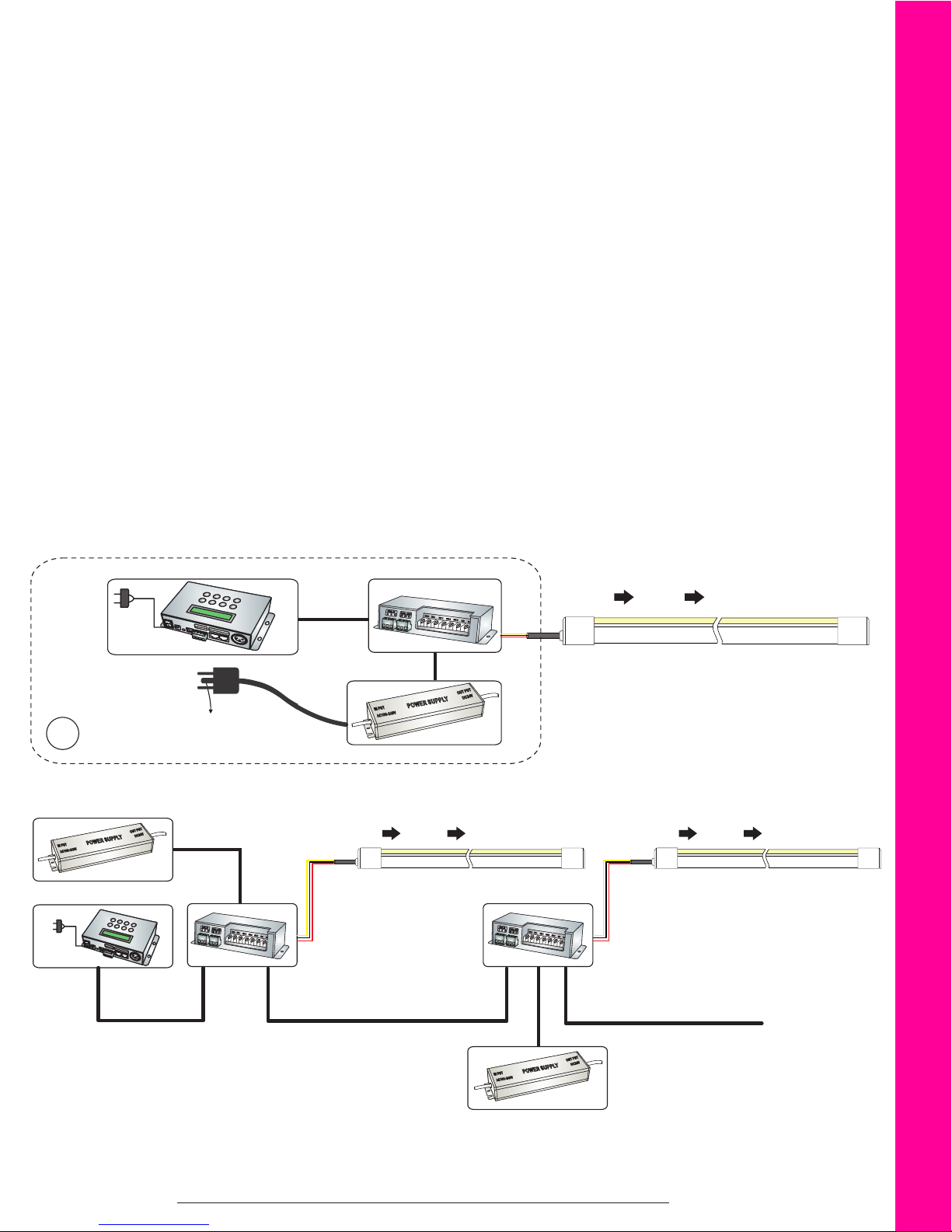
General Wiring Diagrams
Vivid S Wiring
• This LED Neon Flex Fixture is only compatible with a 24V power supply.
• Always observe proper polarity.
• Always add an additional 20% to the maximum load when sizing the power supply.
• Ensure that the power cable drawing current is no more than 80% of its current capacity.
• To minimize the voltage drop and maintain light consistency, do not use excessive lengths of wire
between the power supply and light xture.
INPUT:AC100~240VAC,50-60Hz
OUTPUT:DC24V
GND
A1
INPUT:AC100~240VAC,50-60Hz
OUTPUT:DC24V
GND
A2
Max Continuous length
Driver
Driver
Dimmer(Optional)
(Compatible with most 0~10V
dimming controllers.)
Dimmer(Optional)
(Compatible with most 0~10V
dimming controllers.)
Instructions for Wiring:
Red Wire Connects to Anode(+)
Black Wire Connects to Cathode(-)
The power supply can drive one length or
①
dierent lengths within allowed maximum
length by feeding light one end.
The power supply can drive one length or
②
dierent lengths within allowed maximum
length by feeding light both ends.
Product Number Color Single Feed Double Feed
NF-11D-T-01-2W-E-XXX-24DC Red/Amber 32.81ft (10m) 65.62ft (20m)
NF-11D-T-01-2W-E-XXX-24DC Green/Blue/White 49.21ft (15m) 98.43ft (30m)
17
www.ledneonex.comwww.GLLS.com

General Wiring Diagrams
Vivid RGB Wiring
• This LED Neon Flex Fixture is only compatible with a 24V power supply.
• Always observe proper polarity.
• Always add an additional 20% to the maximum load when sizing the power supply.
• Ensure that the power cable drawing current is no more than 80% of its current capacity.
• To minimize the voltage drop and maintain light consistency, do not use excessive lengths of wire
between the power supply and light xture.
• Accepts PWM input. Compatible with DMX decoders.
• Accepts PWM input. Compatible with DMX decoders.
Instructions for Wiring Vivid RGB:
Yellow Wire Connects to Anode(+).
Red Wire Connects to the“R”Terminal, Cathode(-).
Green Wire Connects to the “G”Terminal, Cathode(-).
Blue Wire Connects to the“B”Terminal, Cathode(-).
GND
B1
GND
B2
INPUT:AC100~240VAC,50-60Hz
OUTPUT:DC24V
Driver
INPUT:AC100~240VAC,50-60Hz
OUTPUT:DC24V
Driver
RGB Controller
RGB Controller
①
The RGB light can be powered on by connecting one end to the controller. It can be
dierent lengths or combined with other
connectors, but each length must not exceed
10m and the combined lengths cannot overload the controller.
The RGB light can be powered on by connect-
②
ing both ends to the controller within allowed
maximum 20m.
Max Continuous length
Product Number Single Feed Double Feed
NF-11D-T-01-4W-E-XXX-24DC Seamless: 22.97ft (7m) 45.93ft (14m)
Snap: 32.81ft (10m) 65.62ft (20m)
18
www.ledneonex.comwww.GLLS.com
General Wiring Diagrams
Vivid Pixel Wiring
• This LED Neon Flex Fixture must be operated with a 24V power supply and IC-UCS2903 compatible
controller or decoder.
• Polarity symbols, GND, signal line connection should match on each component properly.
• Always add an additional 20% to the maximum load when sizing the power supply.
• Ensure that the power cable drawing current is no more than 80% of its current capacity.
• To minimize the voltage drop and maintain light consistency, do not use excessive lengths of wire
between the power supply and light xture.
• Accepts PWM input. Compatible with DMX decoders.
• Vivid Pixel is one directional. The signal input direction is always indicated by an arrow marked on
the side of light.
Instructions for Wiring Vivid Pixel:
Red Wire Connects to the“VCC”or Anode(+) Terminal
Yellow Wire Connects to the “Signal”Terminal.
Black Wire Connects to the“GND”or Cathode(-) Terminal
DMX ControllerDMX Decoder
①
POWER
ON
/OFF
LED CO
N
TROLLER
DC V1
2
DM
X
OUT
A B G G
DMX OUT
A B N N N N G G
DMX OUT
Signal
C1
DMX Controller
P
O
W
E
R
O
N
/
O
F
F
LE
D
D
C
O
NTROL
C
V
L
1
E
2
R
DMX OUT
A B G G
DM
X O
A B N N N N G G
U
T
DMX OUT
DMX Output
GND
INPUT:AC100~240VAC,50-60Hz
OUTPUT:DC24V
DMX Decoder
DMX Input
DMX Output DMX InputDMX Output
Signal
Signal
DMX Decoder
19
www.ledneonex.comwww.GLLS.com

INPU
50-60H
③
General Wiring Diagrams
Vivid Pixel Wiring
INPUT:AC100~240VA C,
50-60Hz OUTPUT:DC24V
IC-UCS2903 Compatible
Controller
Vivid Pixel can be powered on by connecting one
end to the controller. It can be dierent lengths or
combined with other connectors, but each length
must not exceed 15m and the combined lengths
cannot overload controller.
GND
GND
INPUT:AC100~240VA C,
50-60Hz OUTPUT:DC24V
IC-UCS2903 Compatible
Controller
INPUT:AC100~240VA C,50-60Hz
OUTPUT:DC24V
Signal
INPUT:AC100~240VA C,50-60Hz
OUTPUT:DC24V
Signal
Red and Black Wire
Power Feed Only
Vivid Pixel can be powered on by
connecting both ends to the controller
within allowed maximum 30m.
INPUT:AC100~240VA C,50-60Hz
OUTPUT:DC24V
T:AC100~240VA C,
z OUTPUT:DC24V
IC-UCS 2903 Compatible
Controller
Signal
Vivid Pixel can be powered on by series connecting to the controller within allowed maximum length.
Max Continuous length
Product Number Single Feed Double Feed
NF-11D-T-01-3W-E-XXX-24DC 32.81ft (10m) 65.62ft (20m)
Signal
Use power T-Fe ed connector
20
www.ledneonex.comwww.GLLS.com

General Wiring Diagrams
Dynamic White Wiring
• This LED Neon Flex Fixture is only compatible with a 24V power supply.
• Always observe proper polarity.
• Always add an additional 20% to the maximum load when sizing the power supply.
• Ensure that the power cable drawing current is no more than 80% of its current capacity.
• To minimize the voltage drop and maintain light consistency, do not use excessive lengths of wire
between the power supply and light xture.
• Accepts PWM input. Compatible with DMX decoders.
Instructions for Dynamic White Wiring:
Red Wire Connects to Anode(+).
Yellow Wire Connects to Low Color Temperature Connection, Cathode(-).
Black Wire Connects to High Color Temperature Connection, Cathode(-).
INPUT:AC100~240VAC,50-60Hz
OUTPUT:DC24V
GND
B1
GND
B2
INPUT:AC100~240VAC,50-60Hz
OUTPUT:DC24V
Driver
Driver
Max Continuous length
Color T emperature Controller
Color T emperature Controller
①
The Dynamic White light can be powered on
by connecting one end to the controller. It can
be dierent lengths or combined with other
connectors, but each length must not exceed
10m and the combined lengths cannot overload the controller.
The Dynamic White light can be powered on
②
by connecting both ends to the controller
within allowed maximum 20m.
Product Number Single Feed Double Feed
NF-11D-T-01-3W-E-XXX-24DC 32.81ft (10m) 65.62ft (20m)
21
www.ledneonex.comwww.GLLS.com
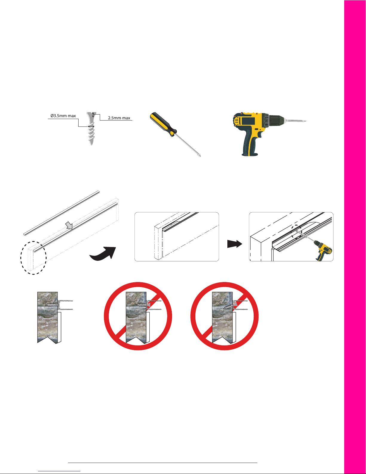
Mounting Channels
Standard, Plastic, & Spring Clip Channel
Tools for Installation
Screw Screwdriver Drill
Correct Installation of Standard Aluminum Channel
Screw into position and
ensure the screw head is
ush with the lower base
of the aluminum prole.
Screw head not ush. Screw at an angle.
22
www.ledneonex.comwww.GLLS.com
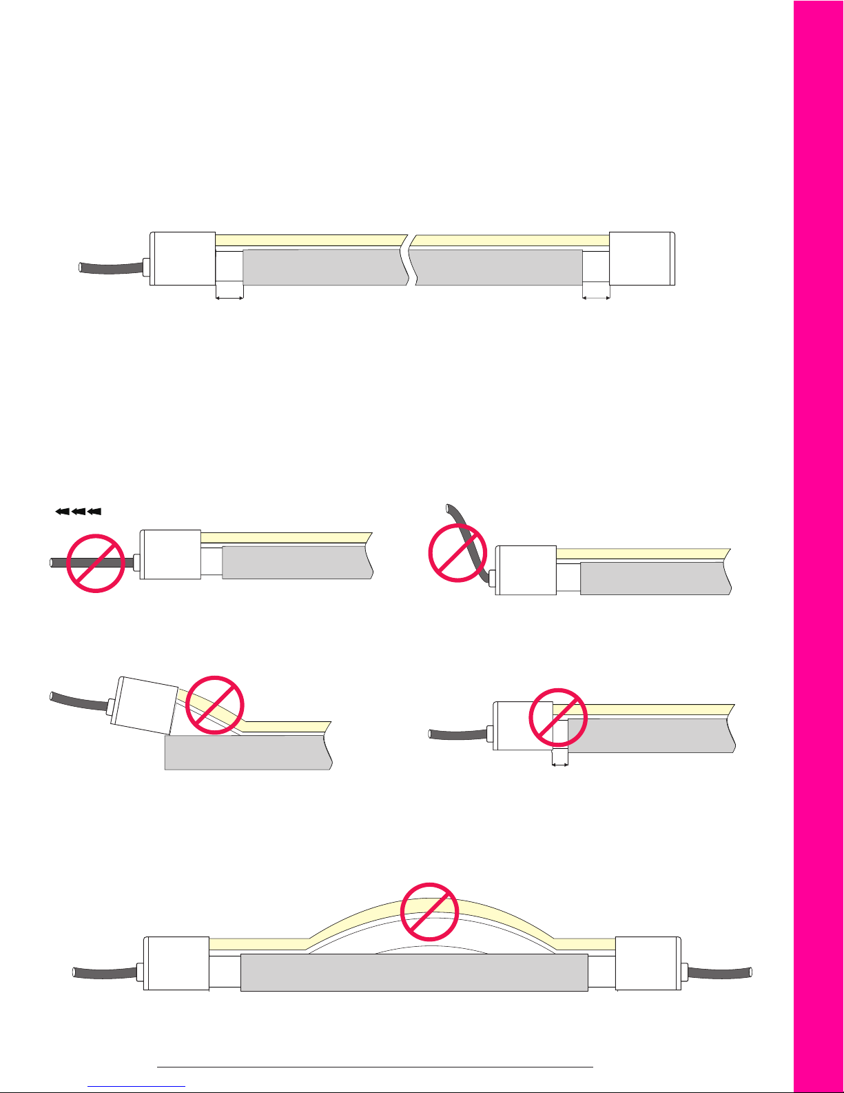
Mounting Channels
Mounting Channel Do’s and Don’ts
Snap, Swivel & Submersible Connectors and Ends
Do not put undue stress on the cables or connectors.
Leave a space of 0.4 to 0.8in (10 to 20mm) between the end of the channel and the connector.
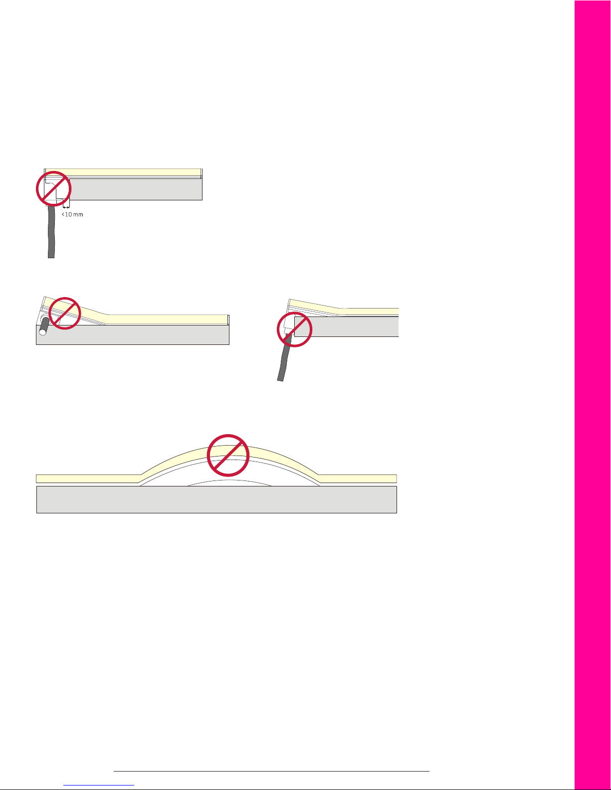
Incorrect Instalation Methods
Do not put undue stress on the cables or connectors. Do not curl or pull the cable with excessive force.
Do not bend the xture at a sharp angle during installation. Do not leave a space smaller than 0.4in (10mm) between the
connector and the channel.
To avoid warping in the center, only install the xture from one end to the other.
23
www.ledneonex.comwww.GLLS.com
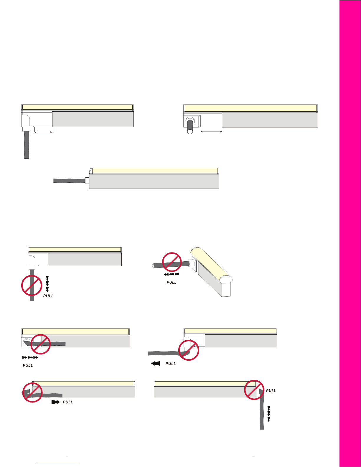
Mounting Channels
Mounting Channel Do’s and Don’ts
Seamless Connectors and Ends
Do not put undue stress on the cables or connectors.
Leave a space of 0.4 to 0.8in (10 to 20mm) between the end of the channel and the Side or Bottom Exit connector.
For End Exit connectors, make sure the end of the xture is ush with the channel.
Incorrect Instalation Methods
Do not put undue stress on the cables or connectors.
Do not curl or pull the cable with excessive force.
24
www.ledneonex.comwww.GLLS.com
Mounting Channels
Mounting Channel Do’s and Don’ts
Seamless Connectors and Ends (cont)
Do not leave a space smaller than 0.4in (10mm) between the connector and the channel.
Do not force the connectors to t into the mounting channel.
To avoid warping in the center, only install the xture from one end to the other.
25
www.ledneonex.comwww.GLLS.com

01
0
2
Mounting Channels
Mounting Channel Do’s and Don’ts
Correct Bending During Installation
When pressing the xture into the channel, do not bend the xture at an angle greater than 15 degrees.
Avoid bending the light at the rst cutting unit. Do not push the xture to bend smaller than the minimum
bending diameter.
1uni t
<1uni t
01
02
1uni t
The min.be nd diam eter
02
01
The min.be nddiame te r
26
www.ledneonex.comwww.GLLS.com

Troubleshooting
Entire xture doesn’t work.
• Check that the power supply is plugged in, switched on and receiving power.
• Check all light, dimmer or controller connections, connecting from the power supply to the xture.
• Check polarity of all wire connections.
• Make sure power supply output voltage is 24V DC.
• Ensure connector pins are inserted into back side of PCB and properly assembled.
• Make sure your power supply is CV (constant voltage).
Light appears dim or dull at one end.
• Make sure the voltage of the power supply is not lower than that of the light.
• Adjust the dimming level to maximum.
• Attach a lead wire to both ends of the xture shorten xture length to prevent voltage drop.
Light appears excessively bright / is hot to the touch.
• Make sure the voltage of the power supply is not higher than that of the light.
If the rst segment doesn’t work.
• Make sure unit s properly cut. If it has been cut wrong, remove the rst segment, cutting it o properly.
• Check for damage done to the rst LED from improper installation of the connector. If damage has been done, cut out the
rst segment and properly assemble the connector.
• Water ingress due to improper connector assembly could cause a short in the rst segment. Replace length with a new
one.
• External impact damage inside LEDs. Only use your hands to install LED Neon Flex into aluminum prole.
Light is ashing on and o.
• Check the power supply to ensure it supports the length you are using. Select the appropriate strength or install an
additional power supply to support your installation.
• Check that the power supply output voltage is stable.
• Check that front connector is properly installed with good contact with the copper PCB.
• Check that the proper controller is connected.
For more information, and troubleshooting, please refer to our Knowledge Base at www.glls.com/knowledge-base/
27
www.ledneonex.comwww.GLLS.com

3 or 5 Year Limited Warranty
Green LED Lighting Solutions (GLLS) provides a standard 3 year (36-month) limited warranty for “LED Neon Flex Vivid” products
manufactured with PVC encapsulations from the date of purchase to the original buyer. GLLS also provides a 5 year (60-month)
limited warranty for certain “LED Neon Flex Vivid” products when manufactured with Silicone encapsulations from the date of
purchase to the original buyer. This limited warranty covers manufacturer defects in the material and workmanship, only on the faulty
section of the LED Neon Flex Vivid light. Replacement is provided only on the defective section of the LED Neon Flex Vivid light as dened
by its cutting marks. The owner(s) will need to provide proof of purchase at the time of exchange.This Limited Warranty is valid only when
LED Neon Flex Vivid lights are used together with LED Neon FlexVivid approved power supplies, controllers and dimmers for their intended
purpose and are properly installed and wired in accordance with all instructions, building codes, the latest UL Standards of Safety, NEC, CSA
or any other domestic or international safety agencies.
Standard 3 year limited warranty applies to connectors as well. The 5 year limited warranty on Silicone xtures will apply to the connectors
as well.
Warranty Terms and Conditions
Exclusions
GLLS will not cover damage by abuse, misuse, curvature past the recommended bend radius, punctures, cuts, shortening or splicing outside
of the designated cutting marks, disregard for proper cleaning, faulty installation, improper maintenance, including forfeiting the use of a
surge protector, or any repairs not carried out by certied LED lighting professionals.
Items not covered by this warranty are those considered as parts which are prone to failure due to normal wear and tear.
GLLS’ warranty does not cover any ancillary costs of warranty such as, but not limited to, equipment costs, labor, permits, removal, or
reinstallation. GLLS’ warranty is a parts only warranty.
Shipping Conditions
All shipping charges should be pre-paid before delivery. If the requested replacement of service is within the terms of the warranty, the item
will be returned to the purchaser postage paid. Any shipping damage due to carrier mishandling or improper packaging is the responsibility
of the sender. If the product is not within the terms of the warranty GLLS will advise the purchaser of the price of replacement and ship it to
the purchaser upon receipt of payment including shipping charges. Please allow 2-4 weeks for return of product. GLLS takes great pride in
our products and our customer service and we try to satisfy each situation within the same business day. We cannot be held responsible for
shipping delays.
To Obtain Warranty Service
If an LED Neon Flex Vivid S product fails under this warranty, please contact a customer service agent at GLLS www.glls.com or 1-888-850-
NEON (6366). GLLS will replace the product at its own discretion, once verication of the defective product is determined. GLLS’s liability on
any claim shall never exceed the purchase price of the specic product.
Exchanges
All exchanges for products will be honored only after the product has been received by the GLLS warehouse or sales oce. The returning
product will be inspected by the warehouse or sales sta and will be deemed acceptable or not acceptable. If deemed acceptable, the
exchanged product will be shipped to the purchaser. All returns judged not acceptable will receive no refund and will not be returned to the
purchaser until the purchaser has paid the return shipping costs.
Shipping on Exchanges
Shipping costs on exchanges will be judged on extenuating circumstances from the original purchase and assessed by the warehouse or
sales sta.
28
www.ledneonex.comwww.GLLS.com

Appendix
Correlated Color Temperature (CCT)
ANSI Standard
Nominal CCT Categories
Nominal CCT Target CCT and tolerance (K) Target Duv and tolerance
2700K 2725 ± 145 0.000 ± 0.006
3000K 3045 ± 175 0.000 ± 0.006
Remark:
1. Six of the nominal CCTs correspond to those in the uorescent
lamp specication 2700K, 3000K (Warm White), 4100K (Cool
White), 5000K and 6500K (Daylight), respectively.
2. ΔT is given by ΔT=0.0000108xT2+0.0262xT+8.
3. Duv is given by Duv=57700x(1/T)2-44.6x(1/T)+0.0085.
3500K 3465 ± 245 0.000 ± 0.006
4000K 3985 ± 275 0.001 ± 0.006
4500K 4503 ± 243 0.001 ± 0.006
5000K 5028 ± 283 0.002 ± 0.006
5700K 5665 ± 355 0.002 ± 0.006
6500K 6530 ± 510 0.003 ± 0.006
Flexible CCT T2) + Δ T3) DUVT4) ± 0.006
(2700-6500K)
Recomended Lead Wire Length According to Power Consumption
Note: 1. Follow the parameters in the below chart, lead wires longer than the specied lengths will create voltage drop and eventually aect the lumen output of light.
2. The 0.3m lead wire is not included in this chart.
3. Lead wire length over 10m is NOT recommended unless under special circumstances, especially for adressable lights.
Total Watts 22AWG/0.34mm² 20AWG/0.53mm² 18AWG/0.82mm² 17AWG/1.04mm² 16AWG/1.38mm² 14AWG/2.07mm² 12AWG/3.29mm² 10AWG/5.62mm²
10W 118.11ft (36m) 196.85ft (60m) 328.08ft (100m) 393.70ft (120m) 459.32ft (140m) 787.40ft (240m) 1312.34ft (400m) 1968.5ft (600m)
20W 59.06ft (18m) 98.43ft (30m) 164.04ft (50m) 196.85ft (60m) 229.66ft (70m) 393.70ft (120m) 656.17ft (200m) 984.25ft (300m)
30W 39.37ft (12m) 65.62ft (20m) 98.43ft (30m) 124.67ft (38m) 147.64ft (45m) 262.47ft (80m) 426.51ft (130m) 656.17ft (200m)
40W 26.25ft (8m) 49.21ft (15m) 72.18ft (22m) 91.86ft (28m) 114.83ft (35m) 196.85ft (60m) 311.68ft (95m) 459.32ft (140m)
50W 19.69ft (6m) 39.37ft (12m) 59.06ft (18m) 72.18ft (22m) 91.86ft (28m) 157.48ft (48m) 246.06ft (75m) 344.49ft (105m)
60W 16.40ft (5m) 32.81ft (10m) 49.21ft (15m) 59.06ft (18m) 72.18ft (22m) 118.11ft (36m) 196.85ft (60m) 288.71ft (88m)
70W / 26.25ft (8m) 39.37ft (12m) 45.93ft (14m) 59.06ft (18m) 98.43ft (30m) 164.04ft (50m) 236.22ft (72m)
80W / 19.69ft (6m) 32.81ft (10m) 36.09ft (11m) 45.93ft (14m) 78.74ft (24m) 131.23ft (40m) 190.29ft (58m)
90W / 13.12ft (4m) 22.97ft (7m) 26.25ft (8m) 32.81ft (10m) 59.06ft (18m) 98.42ft (30m) 147.64ft (45m)
100W / / 16.40ft (5m) 19.69ft (6m) 22.97ft (7m) 39.37ft (12m) 72.18ft (22m) 104.99ft (32m)
110W / / 9.84ft (3m) 13.12ft (4m) 16.40ft (5m) 26.25ft (8m) 49.21ft (15m) 72.18ft (22m)
120W / / 6.56ft (2m) 8.20ft (2.5m) 9.84ft (3m) / 26.25ft (8m) 39.37ft (12m)
Loading Chart
Power 35W 60W 100W 120W 150W 150W 180W 240W 320W
7.2W Length 16.40ft (5m) 24.61ft (7.5m) 39.37ft (12m) 49.21ft (15m) / 60.70ft (18.5m) 72.18ft (22m) 98.43ft (30m) /
12W Length 8.20ft (2.5m) 14.76ft (4.5m) 24.61ft (12m) 29.53ft (9m) 32.81ft (10m) / 44.29ft (13.5m) 59.06ft (18m) 65.62ft (20m)
Connections Single Double
29
www.ledneonex.comwww.GLLS.com
 Loading...