

LED Linear VarioContour 0005, VarioContour 0002, VarioContour 0013, VarioContour 0022, VarioContour 0016 Installation Instructions Manual
Page 1
INSTALLATION INSTRUCTIONS
MODELS: VarioContour 0002/0005/0013/0016/0022
ATTENTION
Please read all safety and assembly instructions prior to installation and keep for future reference.
1. Product should be installed by a qualified electrician with regards to all applicable electrical and safety standards.
2. Ensure power is shut off at the electrical panel prior to installation in order to prevent electrical shock.
3. Use only with SELV (Safety Extra Low Voltage)/Class 2 power supplies.
4. Suitable for installation in Dry Locations.
5. Avoid looking directly into the light source during operation - glare hazard.
6. Do not store packed units over 70° F and over 50% humidity more than 12 months.
NOTE
Prior to installation, always test the LED tape with a suitable power supply in order to confirm operation and that the factory
connections are secure. LED Linear only honors warranty for supplied material and is not liable for installation errors.
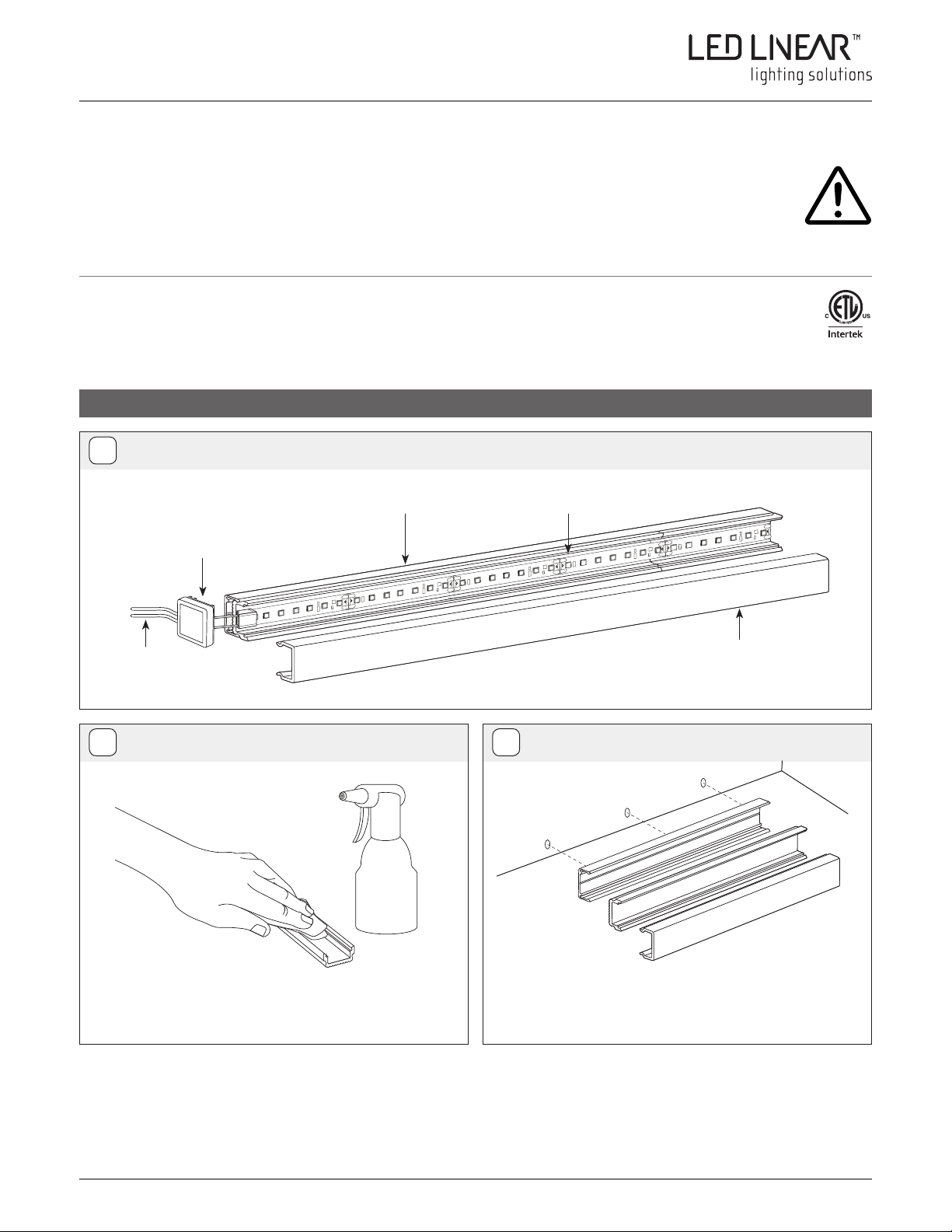
INSTALLATION IN ALUMINUM PROFILE (VarioContour 0002 is illustrated)
Overview
1
Mounting channel is
installed along the full
length of the extrusion.
End caps and mounting channels are
included with the extrusion order.
(Models 0002, 0005, 0013, 0016, 0022)
Place extrusions end to end to extend runs. Offset the mounting
channel to accommodate two extrusions to snap and make
seamless & secure connection.
Extend wires to a wiring
box or directly to the power
supply.
Preparing the Surface Measuring
2 3
50/50
Mounting Channel
ALC
Thoroughly clean the area where tape lights will be installed. Using a 50/50
alcohol mix, clean the area where LEDs will be applied and allow time for
alcohol to dry for 5 minutes.
Align the mounting channel to the determined location. Mark reference
points to install to the surface. The location of the power supply or wiring
box should be determined prior to installation.
Reference mark
Extrusion
Extrusion mounting channel and lens should be cut
to size separately. Make sure to match lengths and
avoid cracking of the lens.
Reference mark
Reference mark
Lens
Measure and then mark
the reference points
LED Linear™ USA, Inc. | Edition: 30/01/2019 | LED LINEAR RESERVES THE RIGHTS TO CHANGE SPECIFICATIONS WITHOUT NOTICE
1 (2)
Page 2
INSTALLATION INSTRUCTIONS
MODELS: VarioContour 0002/0005/0013/0016/0022
ATTENTION
Please read all safety and assembly instructions prior to installation and keep for future reference.
Field Cutting Assembling Fixture
4 5
Lens
Extrusion
Mounting Channel
Miter Saw
Mounting Channel
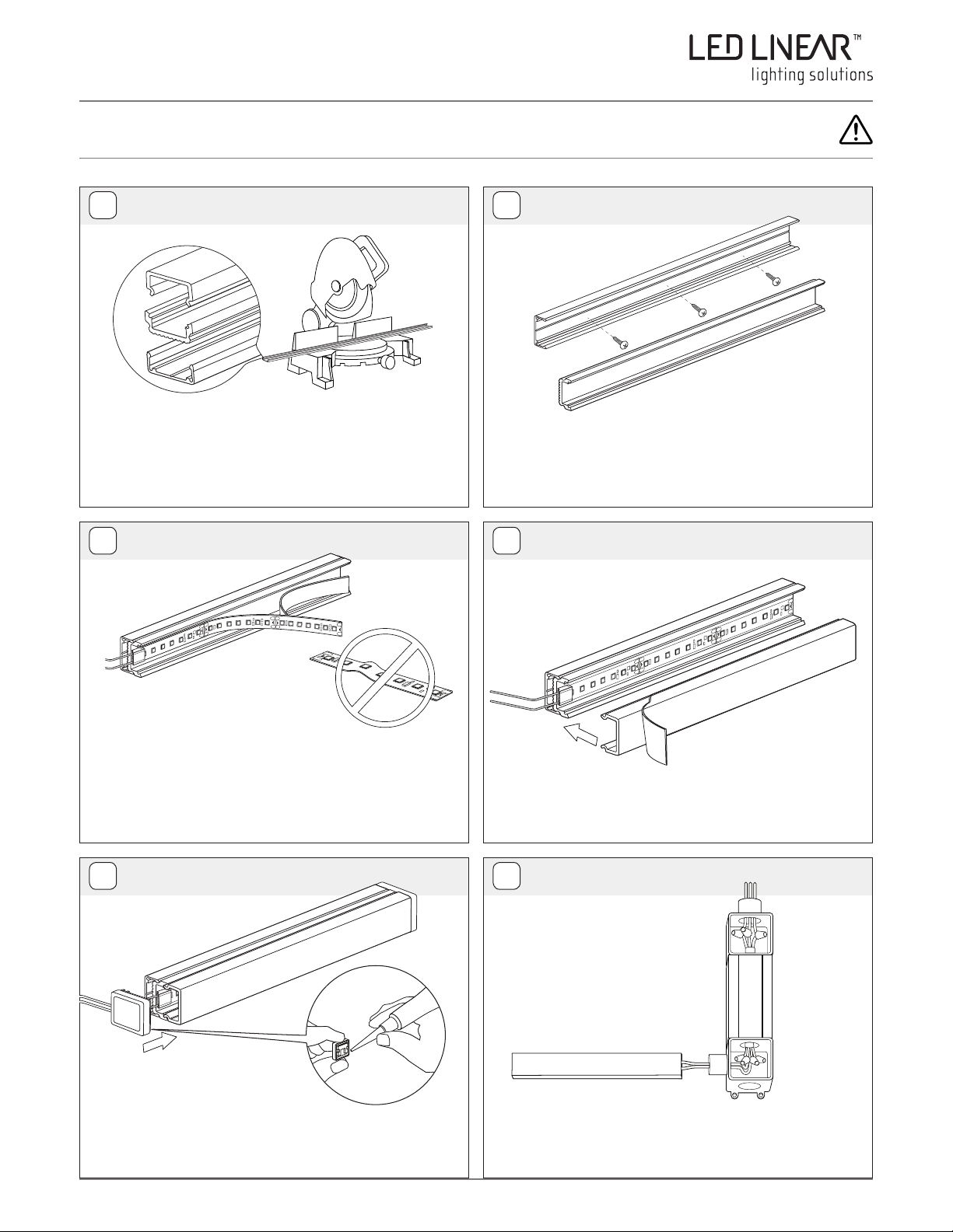
Cut extrusion, lens, & mounting channel to the desired length in the field. For
short runs (<78”), cut all parts to the same length by using the proper blades
for aluminum/plastic cut. For longer runs it is recommended to cut the mounting
channel longer than the extrusion to accommodate end to end connections.
Mounng Channel
Screw
Extrusion
Extrusion
Lay mounting channel onto the surface along the pre-determined locations
and secure using the provided screws. Using the mounting bracket is necessary for relevant models ( 002, 004, 005, 007, 013, 016). Gluing the channel
to surface without using the mounting bracket should be avoided. Snap the
channel into the mounting channel. Offset them for longer runs.
Screw
Assembling Fixture
6
Attach the quick connector or solder lead wires to one side of the tape. Shorten
the LED tape to desired length by cutting along the marked area in between
the solder pads. Remove paper backing from the adhesive tape firmly press
down onto the aluminum surface. Uncoil and peel minimal amount as you
install to avoid collection of debris. Excessive uncoiling and peeling of tape
create ripples and air bubbles on the tape that should be avoided.
Installing Endcaps
8
End Cap
Paper Backing
End Cap
Super Glue
Installing Lens
7
Extrusion
Mounting Channel
Lens
Protective Film
Snap the diffuser lens into the aluminum extrusion. Remove the protective
film from the diffuser lens.
Powering
9
Line Voltage
Class 2
Power Supply
Tape in Aluminum Channel
Feed the lead wires through or behind the endcap. Add Super Glue inside
and around end cap to secure it in place. For select models, use torque bit
to screw the endcap. If applicable, secure the Quick Connector by adding
super glue and pressing it onto the extrusion.
LED Linear™ USA, Inc. | Edition: 30/01/2019 | LED LINEAR RESERVES THE RIGHTS TO CHANGE SPECIFICATIONS WITHOUT NOTICE
Ensure the correct (wattage & voltage) power supply is used to power the
tape. Then proceed to connect low voltage wires from extrusion to power
supply. For more information please refer to power supply and LED tape
wiring instructions.
Low Voltage
2 (2)
 Loading...