

Page 1

PRO LED Starcloths, CW
User Manual
Order codes:
6 x 4m Black Starcloth - STAR41
9 x 4m Black Starcloth - STAR42
7 x 5m Black Starcloth - STAR43
Starcloth Controller - STAR24
Page 2

Safety advice
WARNING - FOR YOUR OWN SAFETY, PLEASE READ THIS USER
MANUAL CAREFULLY BEFORE YOUR INITIAL START-UP!
• Before your initial start-up, please make sure that there is no damage caused during transportation.
• Should there be any damage, consult your dealer and do not use the equipment.
• To maintain the equipment in good working condition and to ensure safe operation, it is necessary
for the user to follow the safety instructions and warning notes written in this manual.
• Please note that damages caused by user modications to this equipment are not subject to warranty.
CAUTION!
KEEP THIS EQUIPMENT
AWAY FROM RAIN,
MOISTURE AND LIQUIDS
CAUTION!
TAKE CARE USING
THIS EQUIPMENT!
HIGH VOLTAGE-RISK
OF ELECTRIC SHOCK!!
IMPORTANT:
The manufacturer will not accept liability for any resulting damages caused by the non-observance
of this manual or any unauthorised modication to the equipment.
• Never let the power cable come into contact with other
cables. Handle the power cable and all mains voltage
connections with particular caution!
• Never remove warning or informative labels from the unit.
• Do not open the equipment and do not modify the unit.
• Do not connect this equipment to a dimmer pack.
• Do not switch the equipment on and off in short intervals,
as this will reduce the system’s life.
• Only use the equipment indoors.
• Do not expose to ammable sources, liquids or gases.
• Always disconnect the power from the mains when
equipment is not in use or before cleaning! Only handle
the power-cable by the plug. Never pull out the plug by
pulling the power-cable.
• Make sure that the available mains supply voltage is
between 100~250V AC, 50/60Hz.
• Make sure that the power cable is never crimped or
damaged. Check the equipment and the power cable
periodically.
• If the equipment is dropped or damaged, disconnect the
mains power supply immediately and have a qualied
engineer inspect the equipment before operating again.
• If the equipment has been exposed to drastic
temperature uctuation (e.g. after transportation),
do not connect power or switch it on immediately.
The arising condensation might damage the equipment.
Leave the equipment switched off until it has reached
room temperature.
• If your product fails to function correctly, stop use
immediately. Pack the unit securely (preferably in the
original packing material), and return it to your Pro Light
dealer for service.
• Only use fuses of same type and rating.
• To clean the cloth, disconnect the mains power supply and
then wipe with a damp cloth. Do not immerse in liquid.
The cloth will require monthly cleaning. Do not use alcohol
or solvents. Connections and LEDs must be kept clean
and dry at all times.
• Repairs, servicing and power connection must only be
carried out by a qualied technician. THIS UNIT CONTAINS
NO USER SERVICEABLE PARTS.
• This starcloth and/or controller is for professional use
only - it is not designed for or suitable for household use.
The product must be installed by a qualied technician
in accordance with local territory regulations. The safety
of the installation is the responsibility of the installer. The
xture presents risks of severe injury or death due to re
hazards, electric shock and falls.
• Warning! Risk Group 2 LED product according to
EN 62471. Do not view the light output with optical
instruments or any device that may concentrate the beam.
• WARRANTY: One year from date of purchase.
OPERATING DETERMINATIONS
If this equipment is operated in any other way, than those described in this manual, the product may suffer damage and
the warranty becomes void. Incorrect operation may lead to danger e.g: short-circuit, burns and electric shocks etc.
Do not endanger your own safety and the safety of others!
Incorrect installation or use can cause serious damage to people and/or property.
www.prolight.co.uk PRO LED Starcloths, CW User Manual
2
Page 3

Product overview & technical specications
SET/ESC ENTERUP DOWN
TRI STARCLOTH
CONTROLLER
SET/ESC ENTERUP DOWN
TRI STARCLOTH
CONTROLLER
POWER INPUT:
100-250V~50/60HZ
FUSE:
F2A 250V
ON OFF
FUSE CURTAIN 1 FUSE CURTAIN 2
DATA OUTPUT 1 DATA OUTPUT 2
www.prolight.co.uk
PRO Starcloths, CW
LEDJ Pro Starcloths utilise cool white randomly placed in a black Molton, re retardant, low maintenance fabric.
The LED strings are arranged in a random formation to give a realistic night sky effect.
Eyelets, holes and Velcro allow for seamless cloth jointing on all 4 sides.
The dedicated controller allows stand alone control of intensity, chase speed, program, and dimmer.
When linked together several drapes can be controlled simultaneously and fully synchronised.
Model LEDs Cloth colour Order code
6 x 4m LED Black Starcloth, CW 168 x 5mm cool white LEDs Black cloth STAR41
9 x 4m LED Black Starcloth, CW 216 x 5mm cool white LEDs Black cloth STAR42
7 x 5m LED Black Starcloth, CW 210 x 5mm cool white LEDs Black cloth STAR43
Starcloth Controller - - STAR24
Cloth:
• Black Molton, low maintenance fabric
• Eyelets, holes and velcro for seamless cloth
jointing on all four sides
Controller:
• DMX channels: 12
• Sound active, auto and master/slave modes
• Independent control of 8 groups of LEDs by DMX
• 0-100% dimming and variable strobe
• 4 push button menu with LCD display
• PowerCON input
• 3-Pin XLR input/output
• 5-Pin XLR input/output
271mm
178mm
Specications
Power supply 100~250V, 50/60Hz
Fuse F2A 250V
Dimensions 6 x 4m - STAR41
9 x 4m - STAR42
7 x 5m - STAR43
61 x 271 x 178mm - STAR24
Weight 13kg - STAR41
20kg - STAR42
19kg - STAR43
1.2kg - STAR24
178mm
POWER INPUT:
100-250V~50/60HZ
www.prolight.co.uk
ON OFF
FUSE:
F2A 250V
DATA OUTPUT 1 DATA OUTPUT 2
FUSE CURTAIN 1 FUSE CURTAIN 2
61mm
MIC
DMX OUTPUTDMX INPUT
www.prolight.co.uk PRO LED Starcloths, CW User Manual
DMX OUTPUTDMX INPUT
3
Page 4

Technical specications
01
06 13 14 15 16 17
01 - LCD display
02 - SET/ESC button
03 - ENTER button
04 - UP button
05 - DOWN button
06 - PowerCON input
08
09 10
07 - On/off switch
08 - Fuse F2A 250V
09 - Fuse curtain 1
10 - Fuse curtain 2
11 - Data output 1
12 - Data output 2
02
121107
03
04
05
13 - Mic
14 - 3-Pin DMX input
15 - 3-Pin DMX output
16 - 5-Pin DMX input
17 - 5-Pin DMX output
In the box (STAR41/42/43):
1 x starcloth &
1 x user manual
In the box (STAR24):
1 x controller,
1 x power cable &
1 x user manual
www.prolight.co.uk PRO LED Starcloths, CW User Manual
4
Page 5
Operating instructions
Manual dimming mode
To access colour macro mode press the “UP/DOWN” buttons to show “SCENE” on the LCD display.
To adjust the dimming and strobe press the “ENTER” button twice and use the “UP/DOWN” buttons to
scroll through the options and press the “ENTER” button to enter each option.
Now use the “UP/DOWN” buttons to adjust the values from 000 - 255.
Press the “ENTER” button to save your setting.
Built in programs
To access any of the 17 built-in programmes press the “UP/DOWN” buttons to scroll through from
“PROGRAM 1” to “PROGRAM 17” on the LCD display. To adjust the dimming, speed or strobe of the
chosen programme press the “ENTER” button twice and use the “UP/DOWN” buttons to scroll through
the options and press the “ENTER” button to enter each option. Now use the “UP/DOWN” buttons to
adjust the values from 000 - 255.
Press the “ENTER” button to save your setting.
Macro mode
To access macro mode press the “UP/DOWN” buttons to show “MACRO” on the LCD display.
It will now run through its built-in programmes in either of the selected sound or auto modes.
Press the “ENTER” button twice to adjust the macro steps from 1-62 using the “UP/DOWN” buttons.
Press the “ENTER” button to save your setting.
DMX mode:
To access the DMX mode press the “UP/DOWN” buttons to show “ADDR:001” on the LCD display.
To set the DMX address press the “ENTER” button twice to show “DMX ADDRESS” on the LCD display
and press the “ENTER” button and use the “UP/DOWN” buttons to set the address from 001 - 512.
Now press the “ENTER” button to save your setting.
In DMX mode there are break options so you can set up how the xture will operate if the DMX signal
breaks. To set this up while you are in the DMX mode press the “ENTER” button twice to access the DMX
menu and use the “UP/DOWN” buttons to show “DMX BREAK” on the LCD display. Press the “ENTER”
button and use the “UP/DOWN” buttons scroll through the options and press “ENTER” to save your
setting.
Stop Run - Will stop the cloth running the current program and stay static when the DMX signal breaks.
Hold Run - Will continue to run the current program when the DMX signal breaks.
Auto Run - Will switch to auto run automatically and run the built-in programmes randomly.
Sound Run - Will switch to sound activation automatically and run the built-in programmes randomly.
www.prolight.co.uk PRO LED Starcloths, CW User Manual
5
Page 6
Operating instructions
Master/slave mode:
To set the unit as the master or slave press the “SET/ESC” button to show “SET MENU” on the LCD
display. Now press the “ENTER” button and use the “UP/DOWN” buttons to scroll to
“MASTER & ALONE”. Press the “ENTER” button and use the “UP/DOWN” buttons to switch from
“MASTER” or “ALONE” (SLAVE). Press the “ENTER” button to save your setting.
Restore default mode:
In this mode you can restore your settings to its original default settings. To do this press the “SET/ESC”
button to show “SET MENU” on the LCD display. Now press the “ENTER” button and use the
“UP/DOWN” buttons to scroll to “RELOAD DEFAULT”. Now press the “ENTER” button and use
the “UP/DOWN” buttons to select either “ON” or “OFF”.
Press the “ENTER” button to save your setting.
Auto & sound mode:
In this mode you can have the built-in programmes running with either auto run or sound active.
To enter this mode press the “SET/ESC” button to show “SET MENU” on the LCD display.
Now press the “ENTER” button and use the “UP/DOWN” buttons to scroll to “AUTO & SOUND”.
Now press the “ENTER” button and use the “UP/DOWN” buttons to select either “AUTO” or “SOUND”.
Press the “ENTER” button to save your setting.
Clear display mode:
In this mode you can have the LCD display to slowly fade out slowly or to stay on constantly. To enter
this mode press the “SET/ESC” button to show “SET MENU” on the LCD display. Now press the “ENTER”
button and use the “UP/DOWN” buttons to scroll to “CLEAR DISPLAY” Now press the “ENTER” button
and use the “UP/DOWN” buttons to select either “DELAY OFF” or “ALWAYS ON”.
Press the “ENTER” button to save your setting.
Key lock mode:
In this mode you can lock the LCD display so no unwanted users can change the settings. To enter this
mode press the “SET/ESC” button to show “SET MENU” on the LCD display. Now press the “ENTER”
button and use the “UP/DOWN” buttons to scroll to “KEY LOCK”. Now press the “ENTER” button and use
the “UP/DOWN” buttons to select either “ON” or “OFF”.
Press the “ENTER” button to save your setting.
Please note: To unlock the display you must press the following sequence:
1: SET/ESC, 2: DOWN, 3: UP, 4: ENTER
Information mode:
In this mode you see the information for web address, name of the product, telephone number,
date and time and the serial number. To enter this mode press the “SET/ESC” button to show
“INFORMATION” on the LCD display. Now press the “ENTER” button and use the “UP/DOWN”
buttons to scroll through each bit of information.
www.prolight.co.uk PRO LED Starcloths, CW User Manual
6
Page 7

Operating instructions
Fixture usage:
In this mode you see how long the unit has been in use for per session and total time. To enter this
mode press the “SET/ESC” button to show “MACHINE TIMER” on the LCD display. Now press the
“ENTER” button and use the “UP/DOWN” buttons to scroll through the time options either “THIS TIME” ,
“TOTAL TIME” or “CLEAR TIME”. To display the time usage press the “ENTER” button.
www.prolight.co.uk PRO LED Starcloths, CW User Manual
7
Page 8
12 channel mode:
Channel Value Function
1 000-255 Master dimmer 0-100%
2 000-009 No function
010-255 Strobe (slow-fast)
3 000-255 Group 1 dimmer 0-100%
4 000-255 Group 2 dimmer 0-100%
5 000-255 Group 3 dimmer 0-100%
6 000-255 Group 4 dimmer 0-100%
7 000-255 Group 5 dimmer 0-100%
8 000-255 Group 6 dimmer 0-100%
9 000-255 Group 7 dimmer 0-100%
10 000-255 Group 8 dimmer 0-100%
11 000-049 No function
050-059 Manual dimming mode
060-069 Program 1
070-079 Program 2
080-089 Program 3
090-099 Program 4
100-109 Program 5
110-119 Program 6
120-129 Program 7
130-139 Program 8
140-149 Program 9
150-159 Program 10
160-169 Program 11
170-179 Program 12
180-189 Program 13
190-199 Program 14
200-209 Program 15
210-219 Program 16
220-229 Program 17
230-239 Macros
240-249 Sound active
250-255 No function
12 000-004 Normal Speed
005-255 Speed (slow-fast)
Operating instructions
www.prolight.co.uk PRO LED Starcloths, CW User Manual
8
Page 9
DMX setup
Setting the DMX address:
The DMX mode enables the use of a universal DMX controller. Each xture requires a “start address”
from 1- 512. A xture requiring one or more channels for control begins to read the data on the channel
indicated by the start address. For example, a xture that occupies or uses 7 channels of DMX and was
addressed to start on DMX channel 100, would read data from channels: 100, 101, 102, 103, 104,
105 and 106. Choose a start address so that the channels used do not overlap. E.g. the next unit in
the chain starts at 107.
DMX 512:
DMX (Digital Multiplex) is a universal protocol used as a form of communication between intelligent
xtures and controllers. A DMX controller sends DMX data instructions form the controller to the xture.
DMX data is sent as serial data that travels from xture to xture via the DATA “IN” and DATA “OUT”
XLR terminals located on all DMX xtures (most controllers only have a data “out” terminal).
DMX linking:
DMX is a language allowing all makes and models of different manufactures to be linked together
and operate from a single controller, as long as all xtures and the controller are DMX compliant.
To ensure proper DMX data transmission, when using several DMX xtures try to use the shortest
cable path possible. The order in which xtures are connected in a DMX line does not inuence the
DMX addressing. For example; a xture assigned to a DMX address of 1 may be placed anywhere in
a DMX line, at the beginning, at the end, or anywhere in the middle. When a xture is assigned a
DMX address of 1, the DMX controller knows to send DATA assigned to address 1 to that unit,
no matter where it is located in the DMX chain.
DATA cable (DMX cable) requirements (for DMX operation):
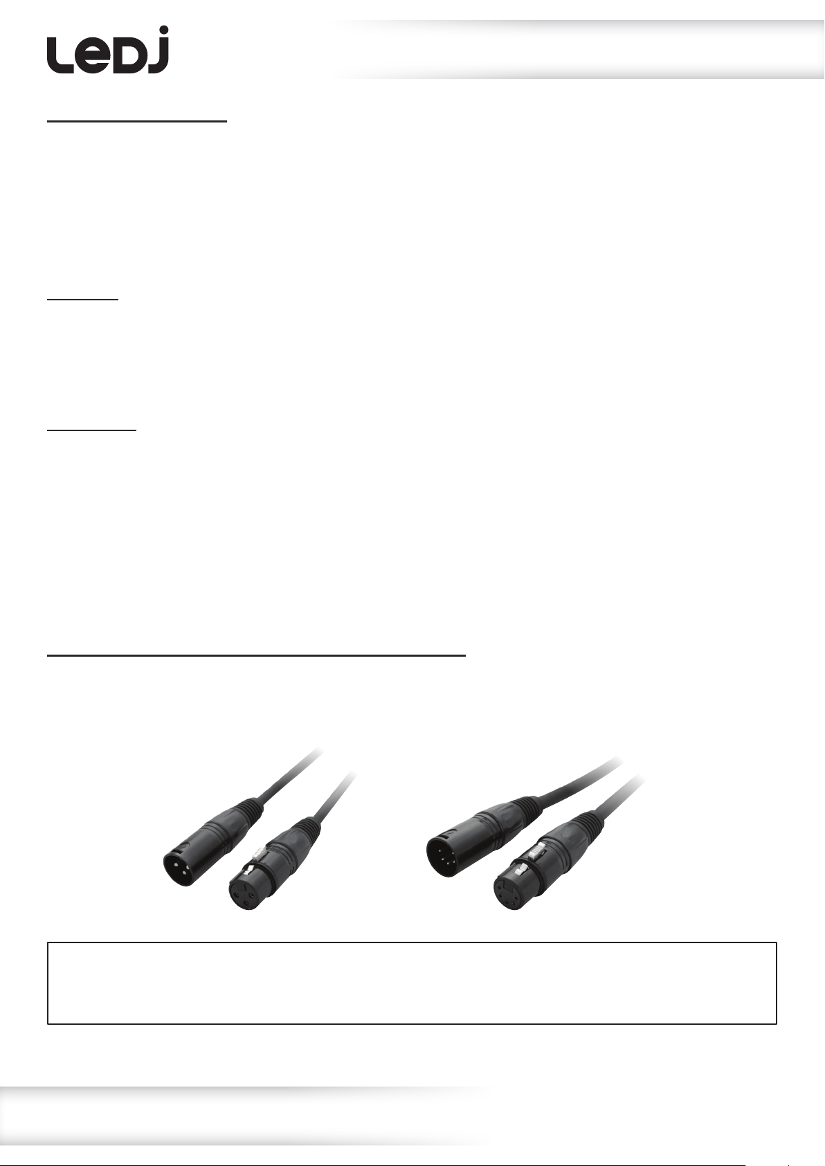
This xture can be controlled via DMX-512 protocol. The DMX address is set on the back of the unit.
Your unit requires either a standard 3-pin or 5-pin XLR connector for data input/output,
see images below.
Further DMX cables can be purchased from all good sound and lighting suppliers or Prolight Concepts dealers.
Please quote:
Also remember that DMX cable must be daisy chained and cannot be split.
CABL10 – 2m CABL11 – 5m CABL12 – 10m3-Pin:
CABL185 – 2m CABL187 – 5m CABL188 – 10m5-Pin:
www.prolight.co.uk PRO LED Starcloths, CW User Manual
9
Page 10
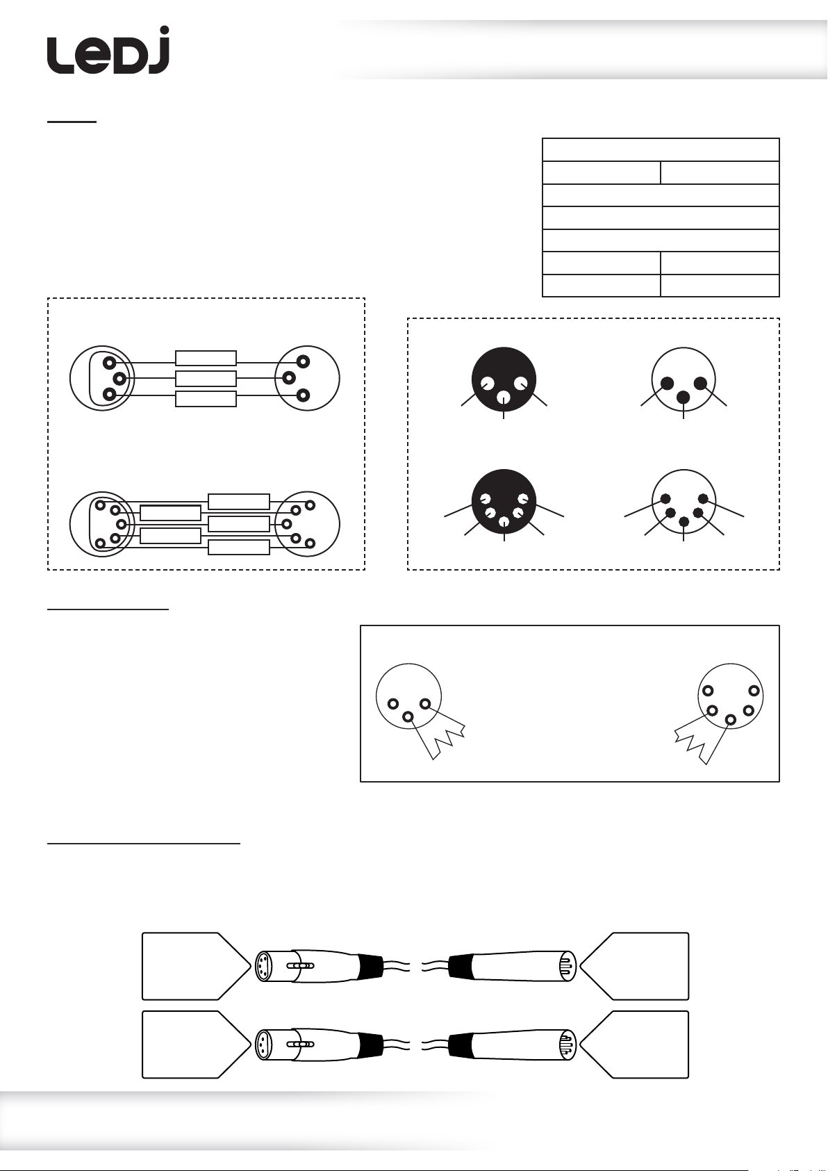
Notice:
DMX setup
Be sure to follow the diagrams below when making your own cables.
Do not connect the cables shield conductor to the ground lug or
allow the shield conductor to come in contact with the XLRs
outer casing. Grounding the shield could cause a short circuit
and erratic behaviour.
DMX 512
3-Pin XLR output
1
3
2
DMX 512
5-Pin XLR output
1
2
3
4
5
GROUND
DMX –
N/C
DMX +
DMX –
GROUND
DMX +
N/C
DMX 512
3-Pin XLR input
1
3
2
DMX 512
5-Pin XLR input
1
2
3
4
5
3-Pin XLR male 3-Pin XLR female
1 ground
3 hot
5-Pin XLR male 5-Pin XLR female
1 ground 5 N/C
2 cold
3 hot
2 cold
4 N/C
Pin Conguration
3-Pin 5-Pin
Pin 1 - Ground
Pin 2 - Negative
Pin 3 - Positive
– Pin 4 - N/C
– Pin 5 - N/C
2 cold
5 N/C 1 ground
4 N/C
3 hot
3 hot
1 ground
2 cold
Line termination:
When longer runs of cable are used,
you may need to use a terminator on
the last unit to avoid erratic behaviour.
Using a cable terminator will decrease
the possibilities of erratic behaviour.
(3-pin - Order ref: CABL90,
3-Pin
1 2
3
Termination reduces signal
transmission problems and
interference. It is always
advisable to connect a DMX
terminal, (resistance 120
Ohm 1/4W) between pin 2
(DMX-) and pin 3 (DMX+) of
the last xture.
5-Pin
1
2 4
3
5
5-pin - Order ref: CABL89)
5-pin XLR DMX connectors:
Some manufactures use 5-pin XLR connectors for data transmission in place of 3-pin. 5-pin XLR xtures
may be implemented in a 3-pin XLR DMX line. When inserting standard 5-pin XLR connectors in to a
3-pin line a cable adaptor must be used. The diagram below details the correct cable conversion.
5-pin XLR (female)
Pin 1: GND (screen)
Pin 2: Signal (-)
Pin 3: Signal (+)
Pin 4: N/C
Pin 5: N/C
3-pin XLR (male)
Pin 1: GND (screen)
Pin 2: Signal (-)
Pin 3: Signal (+)
3-pin XLR (female)
Pin 1: GND (screen)
Pin 2: Signal (-)
Pin 3: Signal (+)
5-pin XLR (male)
Pin 1: GND (screen)
Pin 2: Signal (-)
Pin 3: Signal (+)
Pin 4: N/C
Pin 5: N/C
www.prolight.co.uk PRO LED Starcloths, CW User Manual
10
Page 11
WEEE notice
Correct Disposal of this Product
(Waste Electrical & Electronic Equipment)
(Applicable in the European Union and other European countries
with separate collection systems)
This marking shown on the product or its literature, indicates that it should not be disposed of
with other household wastes at the end of its working life. To prevent possible harm to the
environment or human health from uncontrolled waste disposal, please separate this from other
types of wastes and recycle it responsibly to promote the sustainable reuse of material resources.
Household users should contact either the retailer where they purchased this product, or their
local government ofce, for details of where and how they can take this item for environmentally
safe recycling.
Business users should contact their supplier and check the terms and conditions of the
purchase contract. This product should not be mixed with other commercial wastes for disposal.
www.prolight.co.uk PRO LED Starcloths, CW User Manual
11
Page 12

www.prolight.co.uk PRO LED Starcloths, CW User Manual
12
 Loading...