

Page 1
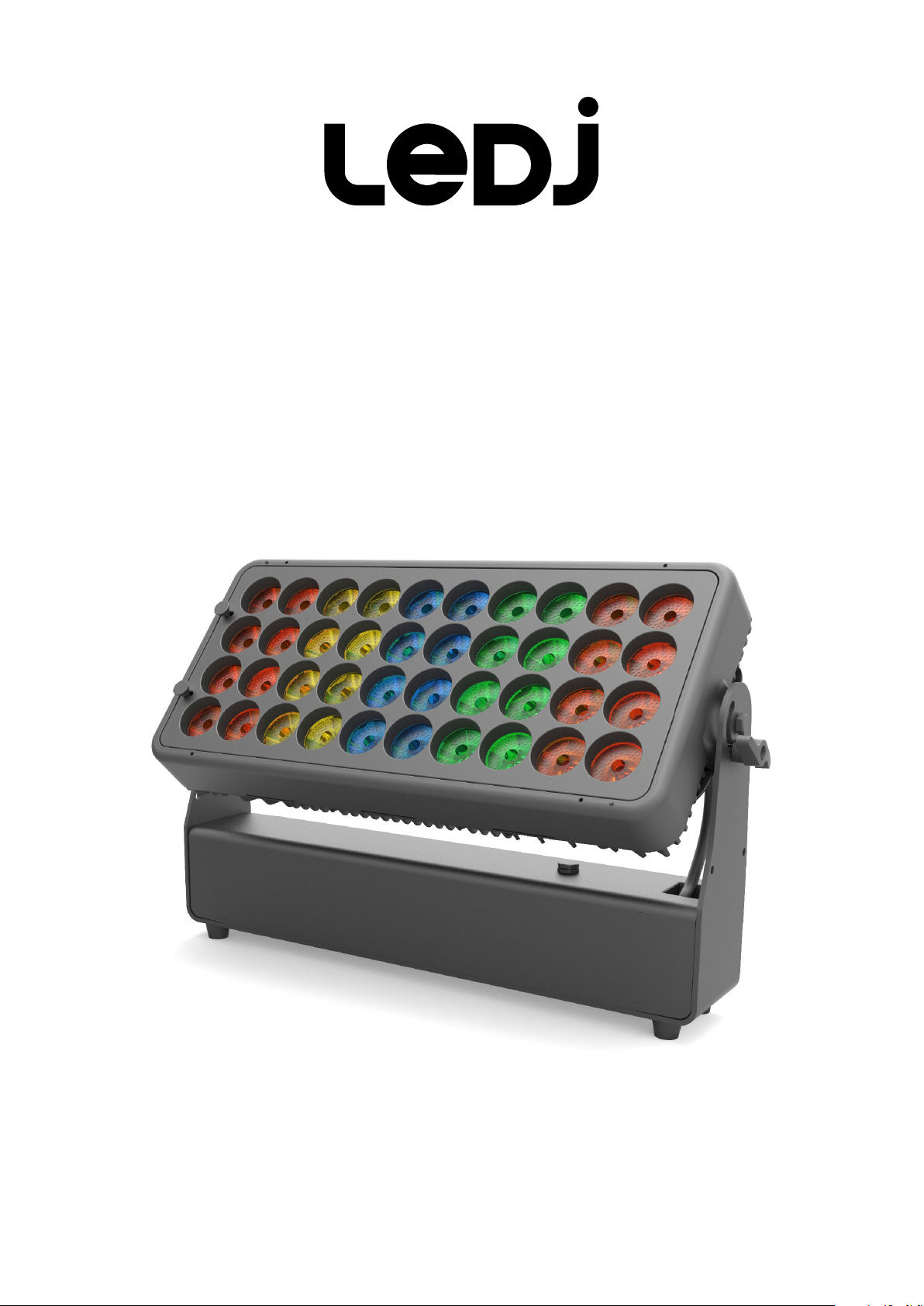
Spectra QX40 Pixel
Exterior Fixture
User Manual
Order code: LEDJ296
Page 2
Safety advice
WARNING
FOR YOUR OWN SAFETY, PLEASE READ THIS USER MANUAL
CAREFULLY BEFORE YOUR INITIAL START-UP!
• Before your initial start-up, please make sure that there is no damage caused during transportation.
• Should there be any damage, consult your dealer and do not use the equipment.
• To maintain the equipment in good working condition and to ensure safe operation, it is necessary
for the user to follow the safety instructions and warning notes written in this manual.
• Please note that damages caused by user modications to this equipment are not subject to warranty.
CAUTION!
TAKE CARE USING
THIS EQUIPMENT!
HIGH VOLTAGE-RISK
OF ELECTRIC SHOCK!!
IMPORTANT:
The manufacturer will not accept liability for any resulting damages caused by the non-observance
of this manual or any unauthorised modication to the equipment.
• Never let the power cable come into contact with other
cables. Handle the power cable and all mains voltage
connections with particular caution!
• Never remove warning or informative labels from the unit.
• Do not open the equipment and do not modify the unit.
• Do not connect this equipment to a dimmer pack.
• Do not switch the equipment on and off in short intervals,
as this will reduce the system’s life.
• Do not expose to ammable sources, liquids or gases.
• Always disconnect the power from the mains when
equipment is not in use or before cleaning! Only handle
the power-cable by the plug. Never pull out the plug by
pulling the power-cable.
• Make sure that the available mains supply voltage is
between 100~240V AC, 50/60Hz.
• Make sure that the power cable is never crimped or
damaged. Check the equipment and the power cable
periodically.
• If the equipment is dropped or damaged, disconnect the
mains power supply immediately and have a qualied
engineer inspect the equipment before operating again.
• If your product fails to function correctly, stop use
immediately. Pack the unit securely (preferably in the
original packing material), and return it to your Pro Light
dealer for service.
• Only use fuses of same type and rating.
• Repairs, servicing and power connection must only be
carried out by a qualied technician. THIS UNIT CONTAINS
NO USER SERVICEABLE PARTS.
• This lighting xture is for professional use only - it is
not designed for or suitable for household use. The
product must be installed by a qualied technician in
accordance with local territory regulations. The safety of
the installation is the responsibility of the installer. The
xture presents risks of severe injury or death due to re
hazards, electric shock and falls.
• Warning! Risk Group 2 LED product according to
EN 62471. Do not view the light output with optical
instruments or any device that may concentrate the beam.
• WARRANTY: One year from date of purchase.
OPERATING DETERMINATIONS
If this equipment is operated in any other way, than those described in this manual, the product may suffer damage and
the warranty becomes void. Incorrect operation may lead to danger e.g: short-circuit, burns and electric shocks etc.
Do not endanger your own safety and the safety of others!
Incorrect installation or use can cause serious damage to people and/or property.
www.prolight.co.uk Spectra QX40 Pixel User Manual
2
Page 3
Product overview & technical specications
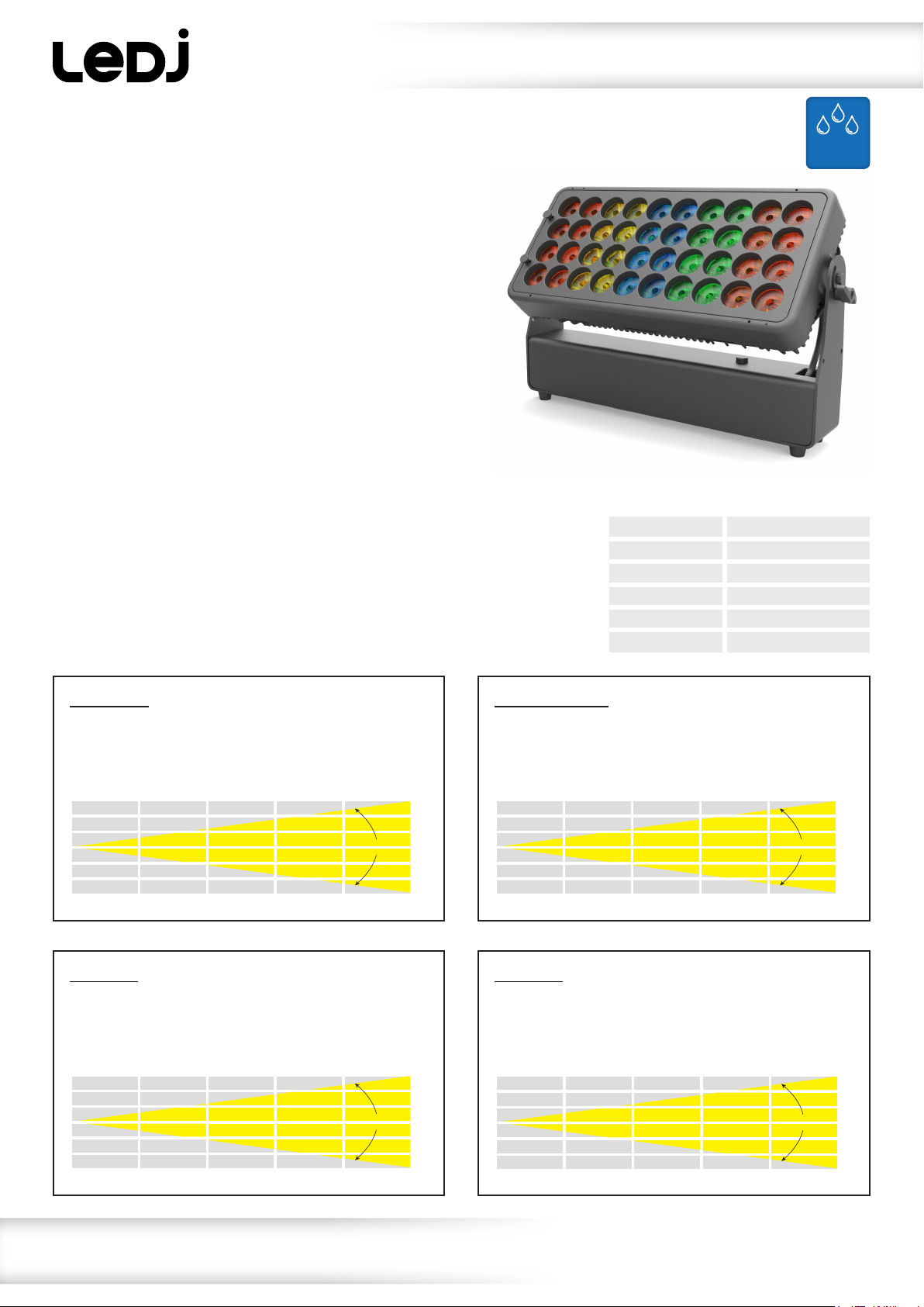
Spectra QX40 Pixel
Equipped with 40 x 10W RGBW LEDs, the QX40 is suitable
for illuminating event spaces, stages or facades, while the
zone control allows lighting designers to create stunning
effects. The unit utilises quad-colour LED technology to
produce a wide colour spectrum from rich, primary colours
through to subtle pastel hues. Designed for rental and events,
the QX40 features quick release omega brackets, powerCON
TRUE1 connectors for power input/output and also features
both wired and wireless DMX by W-DMX Sweden. The slim
prole of the xture is ideally suited for loading into road
trunks holding multiple units. A range of optional accessories
including beam shaping lenses, snoots and barndoors further
widen its applications.
IP65
• 40 x 10W quad-colour LEDs (RGBW)
• Beam angle: 8°
• 3kHz refresh rate
• Pixel zone mapping
• Wireless DMX control
by W-DMX Sweden
• DMX channels: 1/3/4/6/9/20
or 25 selectable
• Static colour, colour change
and colour fade modes
• Master/slave mode when cabled
Native (8°)
8° - Lux
FULL ON
R
G
B
W
236000
47600
82000
17000
112000
58953
11915
20503
4254
28080
26200
5290
9110
1890
12500
• 0 - 100% dimming
and variable strobe
• 4 dimming curves: Linear, square
law, inverse square law and S-curve
• Supplied with installation bracket
and quick release omega clamps
• 4 button menu with OLED display
• PowerCON TRUE1 input/output
• IP rated 5-Pin XLR input/output
trailing connections
• Fan cooled
15° x 60° Lens
14800
2980
5130
1060
7030
9440
1900
3280
680
4500
8°
15° x 60° - Lux
FULL ON
R
G
B
W
26000
5150
9050
2240
12600
Specications Spectra QX40 Pixel
Power consumption 410W
Power supply 100~240V, 50/60Hz
Dimensions 334 x 532 x 138mm
Weight 11.9kg
Order code LEDJ296
7000
1430
2460
600
3460
3150
645
1100
280
1550
1800
370
630
150
880
15° x 60°
1200
245
420
105
590
0m 1m 2m 3m 4m 5m
20° Lens
20° - Lux
FULL ON
R
G
B
W
0m 1m 2m 3m 4m 5m
67600
10100
20860
4070
27210
16910
3089
6147
1327
8041
7555
1360
2768
593
3594
3360
595
1291
269
1670
2720
496
992
213
1290
20°
0m 1m 2m 3m 4m 5m
40° Lens
40° - Lux
FULL ON
R
G
B
W
0m 1m 2m 3m 4m 5m
20420
3707
7475
1460
9670
5220
912
1989
380
2500
2320
411
873
170
1113
1374
244
520
101
660
40°
www.prolight.co.uk Spectra QX40 Pixel User Manual
936
165
354
69
448
3
Page 4
334mm
Technical specications
532mm
492mm
216mm
319mm
90mm
01
07
124mm
138mm
01
08
05 06 09 02 03
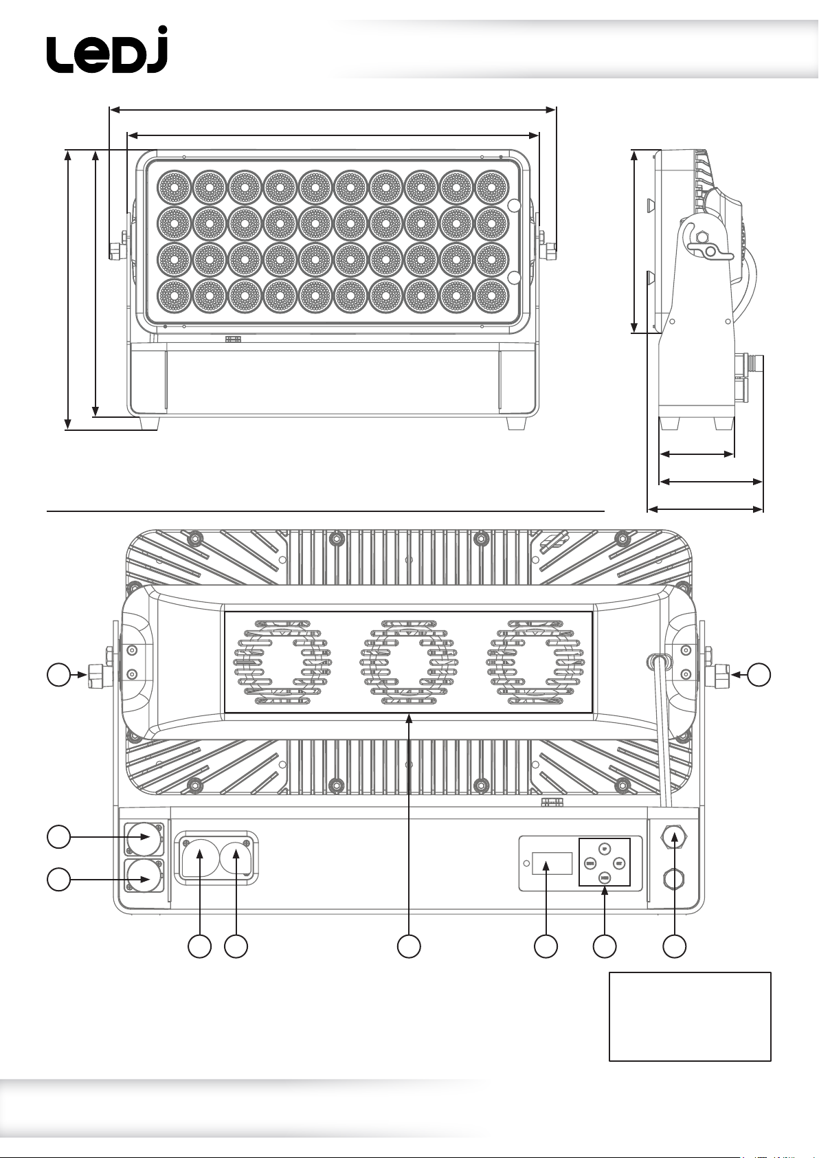
01 - Bracket tightening knobs
02 - OLED display
03 - Function buttons
04 - Wireless DMX antenna
05 - PowerCON TRUE1 input
06 - PowerCON TRUE1 output
07 - IP rated 5-Pin XLR input
08 - IP rated 5-Pin XLR output
09 - Fans
In the box: 1 x xture,
2 x omega clamps,
1 x power cable &
1 x user manual
04
www.prolight.co.uk Spectra QX40 Pixel User Manual
4
Page 5
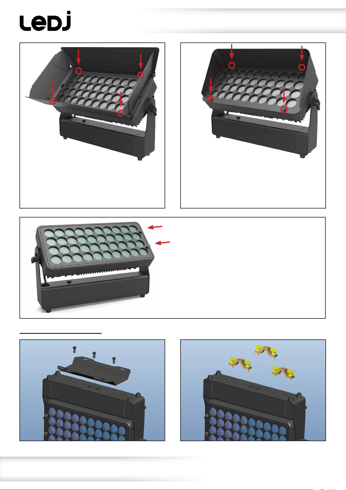
Technical specications
Optional Barn Doors
(Order code: LEDJ296B)
To t the barn doors, place them over the front
lens of the xture and use the four thumbscrews
located in each corner to tighten it to the xture.
The safety wire attached to the barn door can
be clipped to one of the two holes in each of
the side arms.
Optional Snoot
(Order code: LEDJ296S)
To t the snoot, place it over the front lens of the
xture and use the four thumbscrews located in
each corner to tightnen it to the xture.
The safety wire attached to the snoot can
be clipped to one of the two holes in each of
the side arms.
Optional Lenses
(20° - Order code: LEDJ296L)
(40° - Order code: LEDJ296M)
(15 x 60° - Order code: LEDJ296N)
To t the lens, slide the left side with the locating
pegs into the locating slots on the left side of the
xtures frontal glass, pull back the two thumb
spring clips on the right of the lens and lower the
lens so it is ush with the housing. Release the
spring clips which will x the lens in place.
Reverse the above steps to release the lens.
Underside mounting points:
Please note:
Only 2 omega clamps supplied.
www.prolight.co.uk Spectra QX40 Pixel User Manual
5
Page 6
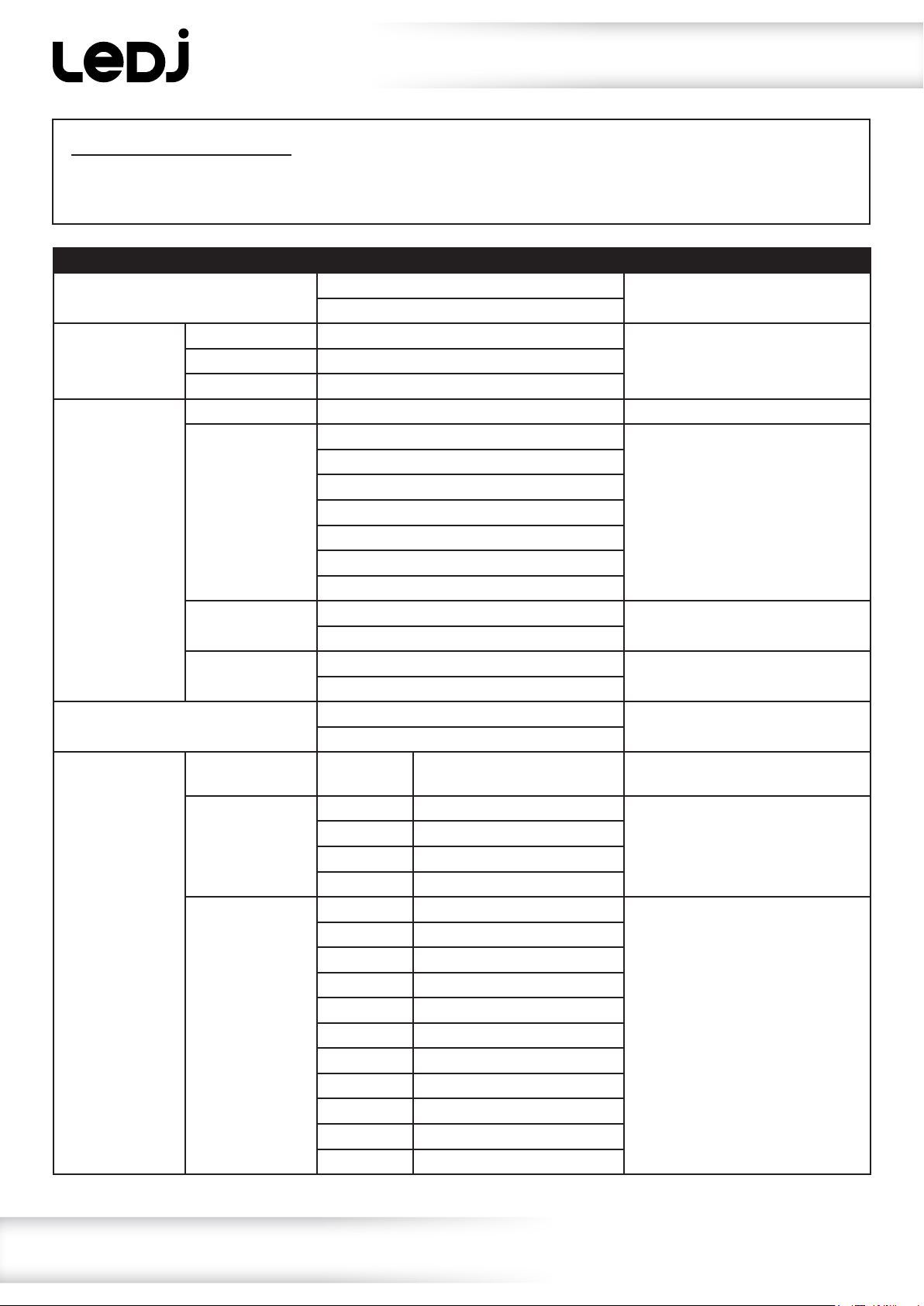
Operating instructions
IMPORTANT! PLEASE NOTE:The OLED display for this xture has a menu locking function where
after 30 seconds ofinactivity it will lock. To unlock the menu hold the “MODE” and “SET” buttons
for 3 seconds.
Main Menu Sub Menu Options/Values Description
1: Auto
1) Mode 01-15
2: Program
3) Strobe 00-99
1) Address 001-512 DMX Address Setting
2) Channels
3: DMX
3) Signal
4) W-DMX Pair
4: Slave
1) Static Mode
2) All Dimmer
5: Dimmer
3) Part Dimmer
Yes
No
01 (1 channel mode)
03 (3 channel mode)
04 (4 channel mode)
06 (6 channel mode)
09 (9 channel mode)
20 (20 channel mode)
25 (25 channel mode)
DMX
W-DMX
Yes
No
Yes
No
Colour
Preset
1) All Red 000-255
2) All Green 000-255
3) All Blue 000-255
4) All White 000-255
1) Red 1 000-255
2) Green 1 000-255
3) Blue 1 000-255
4) White 1 000-255
5) Red 2 000-255
6) Green 2 000-255
7) Blue 2 000-255
8) White 2 000-255
9) Red 3 000-255
10) Green 3 000-255
11) Blue 3 000-255
00-38 (01) Static Colour Mode
Auto Mode
Built-in Programs2) Speed 001-100 (81)
DMX Channel Modes
Wired/Wireless DMX Setting
W-DMX Pair Setting
Slave Mode
Manual Dimming Mode
Zone Manual Dimming Mode
www.prolight.co.uk Spectra QX40 Pixel User Manual
6
Page 7
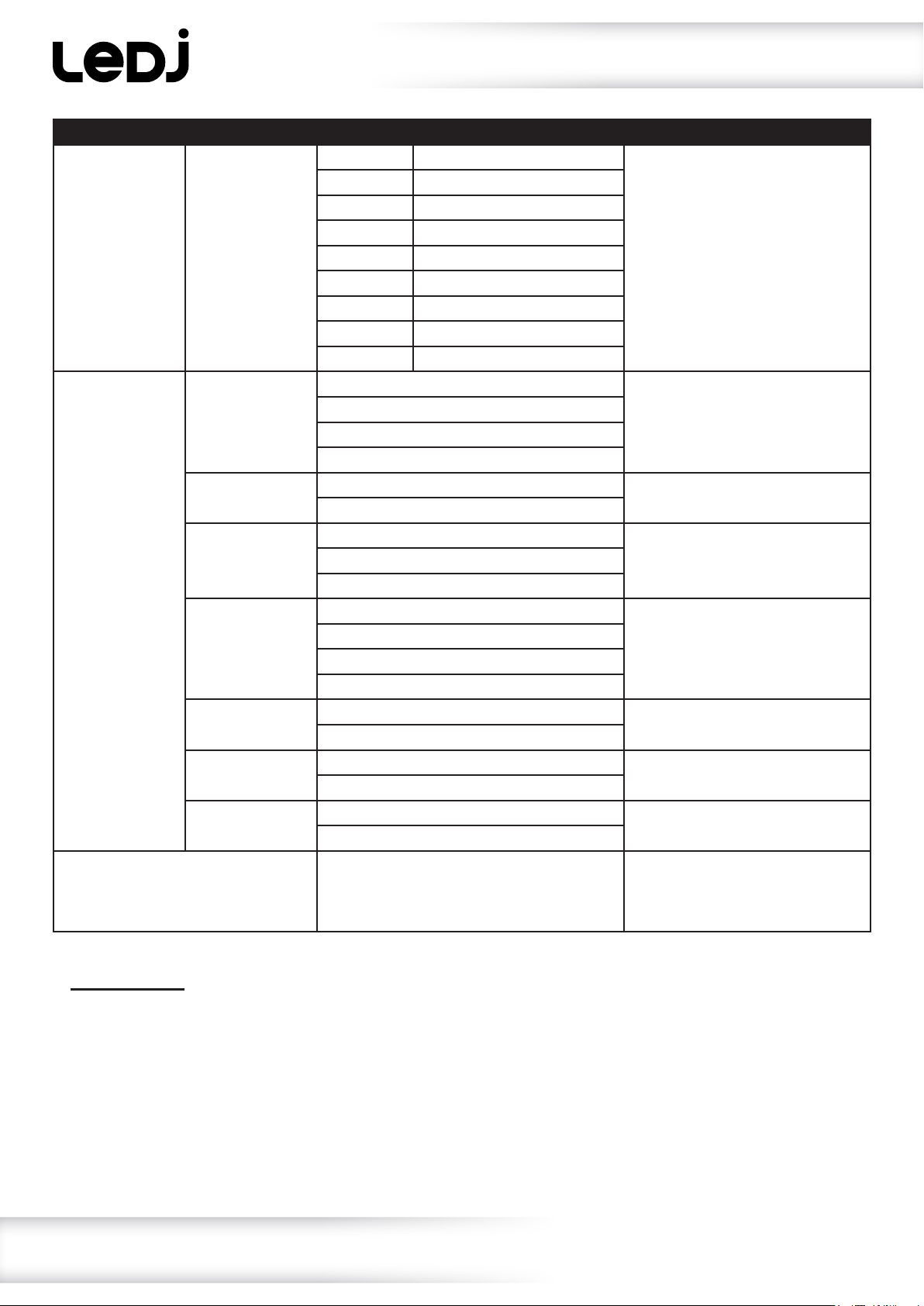
Operating instructions
Main Menu Sub Menu Options/Values Description
17) White 3 000-255
18) Red 4 000-255
19) Green 4 000-255
20) Blue 4 000-255
5: Dimmer 3) Part Dimmer
1) Curves Select
2) Dimmer Speed
3) Fan Speed
6: Setting
4) DMX Fail
5) Dmx Sync
6) Lock
7) Factory
7: Information
16) White 4 000-255
17) Red 5 000-255
19) Green 5 000-255
19) Blue 5 000-255
20) White 5 000-255
1) Linear
2) Square Law
3) Inv Square Law
S-Type
Fast
Smooth
1) Auto
3) Slow
1) Blackout
2) Hold
3) Auto
4) Program
On
Off
On
Off
Yes
No
Versions:
Temperature:
Signal:
UID:
Zone Manual Dimming Mode
Dimming Curve Setting
Dimming Speed Setting
Fan Speed Setting2) High
DMX Fail Setting
DMX Synchronisation Setting
Display Lock Setting
Reset Factory Defaults
Fixture Information
PLEASE NOTE:The DMX Synchronisation setting should be set to on when using the built-in presets
via DMX to ensure the xtures stay synchronised.
www.prolight.co.uk Spectra QX40 Pixel User Manual
7
Page 8
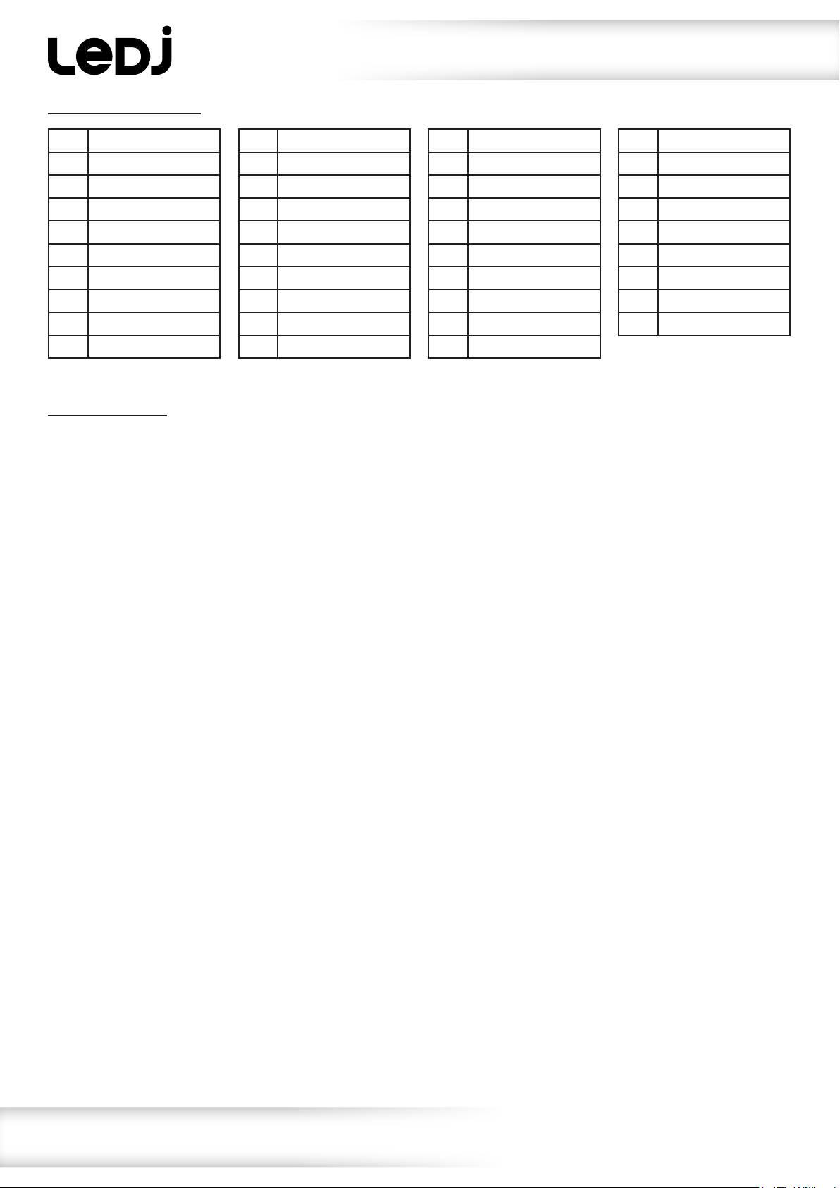
Static colour macros:
Operating instructions
0 Blackout
1 Red
2 Flame Red
3 Deep Golden Amber
4 Millennium Gold
5 Gold Amber
6 Orange
7 Chrome Orange
8 Deep Amber
9 Spring Yellow
10 Lime Green
11 JAS Green
12 Fern Green
13 Moss Green
14 Primary Green
15 Dark Green
16 Green
17 Medium Blue/Green
18 Light Blue
19 Lighter Blue
20 Steel Blue
21 Half CT Blue
22 Full CT Blue
23 State Blue
24 Double CT Blue
25 Medium Blue
26 Just Blue
27 Deep Blue
28 Blue
29 Congo Blue
30 Surprise Pink
31 Fuchsia Pink
32 Follies Pink
33 Special Rose Pink
34 Pink
35 Moroccan Pink
36 Warm White
37 Cold White
38 White
W-DMX settings:
To enable W-DMX, press the “MODE” button and use the “UP” and “DOWN” buttons to select “DMX.
Press the “UP” and “DOWN” button and use the “UP” and “DOWN” buttons to select “Signal”.
Press the “SET” button and use the “UP” and “DOWN” buttons to select “W-DMX”.
Press the “SET” button to conrm the setting and use the “DOWN” button to select “W-DMX Pair”.
Press the “SET” button and use the “UP” and “DOWN” buttons to select “Yes”. Press the “SET” button
to pair the unit with your transmitter. Alternatively you can pair the xture by holding down the “MODE”
button until the display shows “W-DMX Pair”.
The green LED to the left of the display will ash indicating it is searching for a signal.
The green LED will become static once successfully paired.
To disable W-DMX, press the “MODE” button and use the “UP” and “DOWN” buttons to select “DMX.
Press the “UP” and “DOWN” button and use the “UP” and “DOWN” buttons to select “Signal”.
Press the “SET” button and use the “UP” and “DOWN” buttons to select “W-DMX”.
Press the “SET” button to conrm the setting and use the “DOWN” button to select “W-DMX Pair”.
Press the “SET” button and use the “UP” and “DOWN” buttons to select “No”. Press the “SET” button
to conrm the setting.
The green LED will go off to conrm W-DMX has been disabled.
To exit out of any of the above options, press the “MENU” button.
www.prolight.co.uk Spectra QX40 Pixel User Manual
8
Page 9
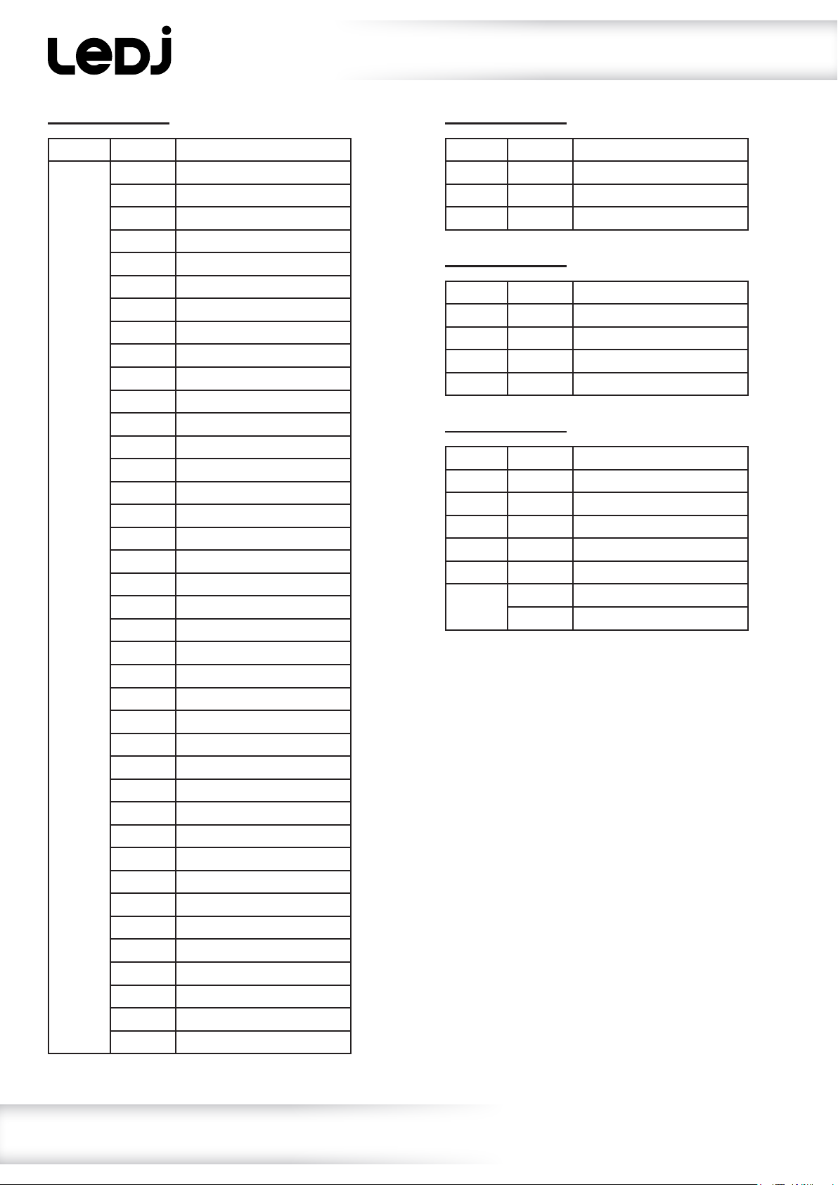
Operating instructions
1 channel mode:
Channel Value Function
1 000-010 Blackout
011-016 Red
017-022 Flame Red
023-028 Deep Golden Amber
029-034 Millennium Gold
035-040 Gold Amber
041-046 Orange
047-052 Chrome Orange
053-058 Deep Amber
059-064 Spring Yellow
065-070 Lime Green
071-076 JAS Green
077-082 Fern Green
083-088 Moss Green
089-094 Primary Green
095-100 Dark Green
101-106 Green
107-112 Medium Blue/Green
113-118 Light Blue
119-124 Lighter Blue
125-130 Steel Blue
131-136 Half CT Blue
137-142 Full CT Blue
143-148 State Blue
149-154 Double CT Blue
155-160 Medium Blue
161-166 Just Blue
167-172 Deep Blue
173-178 Blue
179-184 Congo Blue
185-190 Surprise Pink
191-196 Fuchsuia Pink
197-202 Follies Pink
203-208 Special Rose Pink
209-214 Pink
215-220 Moroccan Pink
221-226 Warm White
227-232 Cold White
233-255 White
3 channel mode:
Channel Value Function
1 000-255 Red (0-100%)
2 000-255 Green (0-100%)
3 000-255 Blue (0-100%)
4 channel mode:
Channel Value Function
1 000-255 Red (0-100%)
2 000-255 Green (0-100%)
3 000-255 Blue (0-100%)
4 000-255 White (0-100%)
6 channel mode:
Channel Value Function
1 000-255 Master dimmer (0-100%)
2 000-255 Red (0-100%)
3 000-255 Green (0-100%)
4 000-255 Blue (0-100%)
5 000-255 White (0-100%)
6 000-010 No function
011-255 Strobe (slow-fast)
www.prolight.co.uk Spectra QX40 Pixel User Manual
9
Page 10
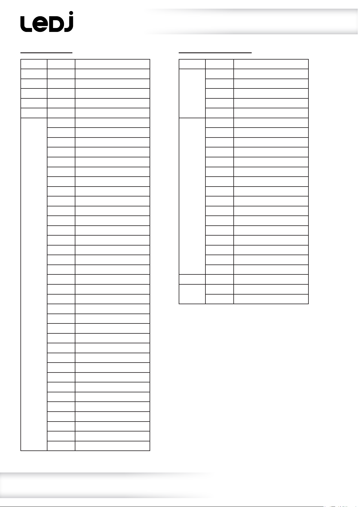
Operating instructions
9 channel mode:
Channel Value Function
1 000-255 Master dimmer (0-100%)
2 000-255 Red (0-100%)
3 000-255 Green (0-100%)
4 000-255 Blue (0-100%)
5 000-255 White (0-100%)
6 000-010 Blackout
011-016 Red
017-022 Flame Red
023-028 Deep Golden Amber
029-034 Millennium Gold
035-040 Gold Amber
041-046 Orange
047-052 Chrome Orange
053-058 Deep Amber
059-064 Spring Yellow
065-070 Lime Green
071-076 JAS Green
077-082 Fern Green
083-088 Moss Green
089-094 Primary Green
095-100 Dark Green
101-106 Green
107-112 Medium Blue/Green
113-118 Light Blue
119-124 Lighter Blue
125-130 Steel Blue
131-136 Half CT Blue
137-142 Full CT Blue
143-148 State Blue
149-154 Double CT Blue
155-160 Medium Blue
161-166 Just Blue
167-172 Deep Blue
173-178 Blue
179-184 Congo Blue
185-190 Surprise Pink
191-196 Fuchsia Pink
197-202 Follies Pink
203-208 Special Rose Pink
9 channel mode (cont.):
Channel Value Function
6 (cont.) 209-214 Pink
215-220 Moroccan Pink
221-226 Warm White
227-232 Cold White
233-255 White
7 000-015 No function
016-031 Program 1
032-047 Program 2
048-063 Program 3
064-079 Program 4
080-095 Program 5
096-111 Program 6
112-127 Program 7
128-143 Program 8
144-159 Program 9
160-175 Program 10
176-191 Program 11
192-207 Program 12
208-223 Program 13
224-239 Program 14
240-255 Program 15
8 000-255 Program Speed (slow-fast)
9 000-010 No function
011-255 Strobe (slow-fast)
www.prolight.co.uk Spectra QX40 Pixel User Manual
10
Page 11
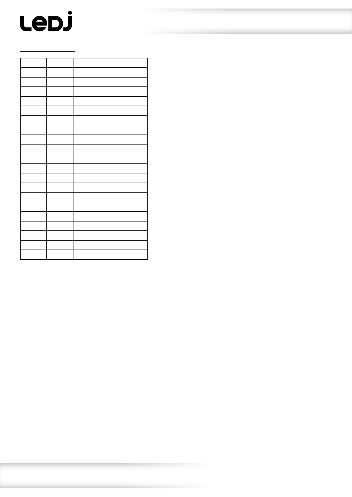
20 channel mode:
Channel Value Function
1 000-255 Red 1 (0-100%)
2 000-255 Green 1 (0-100%)
3 000-255 Blue 1 (0-100%)
4 000-255 White 1 (0-100%)
5 000-255 Red 2 (0-100%)
6 000-255 Green 2 (0-100%)
7 000-255 Blue 2 (0-100%)
8 000-255 White 2 (0-100%)
9 000-255 Red 3 (0-100%)
10 000-255 Green 3 (0-100%)
11 000-255 Blue 3 (0-100%)
12 000-255 White 3 (0-100%)
13 000-255 Red 4 (0-100%)
14 000-255 Green 4 (0-100%)
15 000-255 Blue 4 (0-100%)
16 000-255 White 4 (0-100%)
17 000-255 Red 5 (0-100%)
18 000-255 Green 5 (0-100%)
19 000-255 Blue 5 (0-100%)
20 000-255 White 5 (0-100%)
Operating instructions
www.prolight.co.uk Spectra QX40 Pixel User Manual
11
Page 12
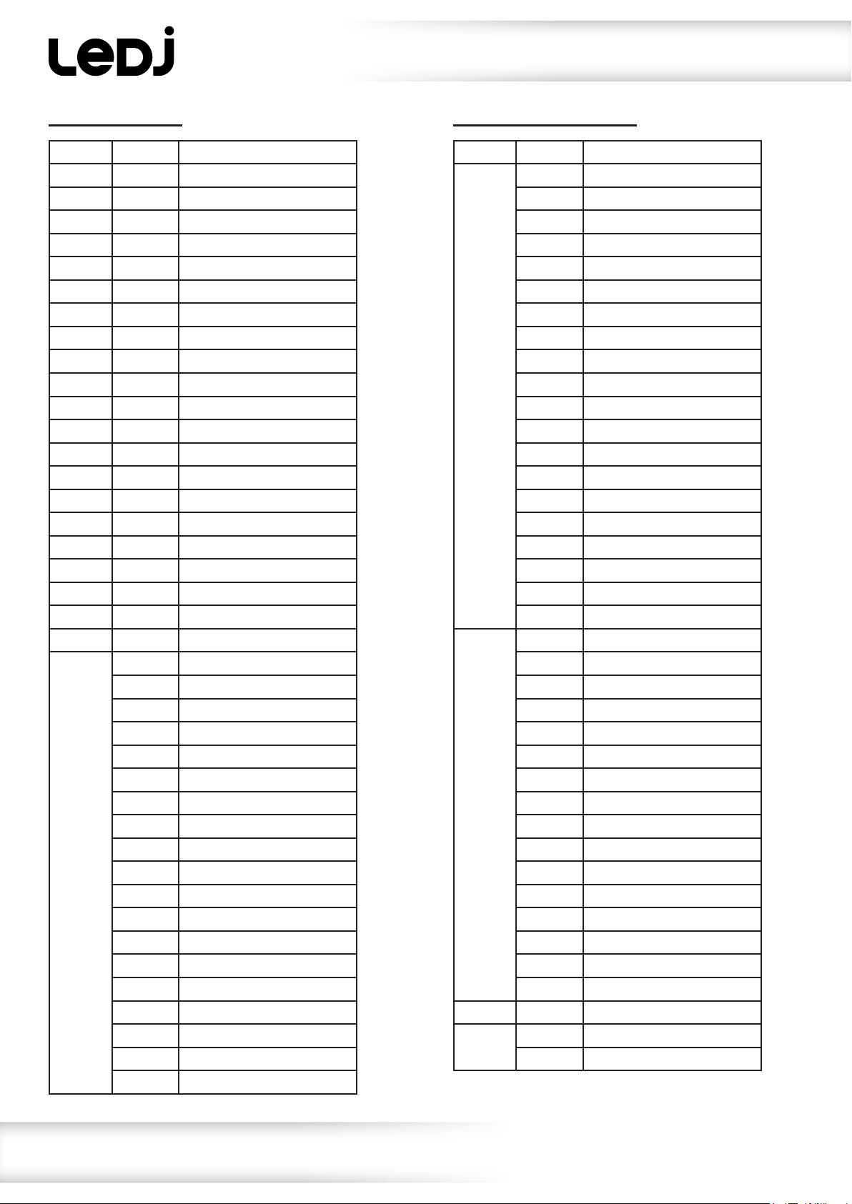
Operating instructions
25 channel mode:
Channel Value Function
1 000-255 Master dimmer (0-100%)
2 000-255 Red 1 (0-100%)
3 000-255 Green 1 (0-100%)
4 000-255 Blue 1 (0-100%)
5 000-255 White 1 (0-100%)
6 000-255 Red 2 (0-100%)
7 000-255 Green 2 (0-100%)
8 000-255 Blue 2 (0-100%)
9 000-255 White 2 (0-100%)
10 000-255 Red 3 (0-100%)
11 000-255 Green 3 (0-100%)
12 000-255 Blue 3 (0-100%)
13 000-255 White 3 (0-100%)
14 000-255 Red 4 (0-100%)
15 000-255 Green 4 (0-100%)
16 000-255 Blue 4 (0-100%)
17 000-255 White 4 (0-100%)
18 000-255 Red 5 (0-100%)
19 000-255 Green 5 (0-100%)
20 000-255 Blue 5 (0-100%)
21 000-255 White 5 (0-100%)
22 000-010 Blackout
011-016 Red
017-022 Flame Red
023-028 Deep Golden Amber
029-034 Millennium Gold
035-040 Gold Amber
041-046 Orange
047-052 Chrome Orange
053-058 Deep Amber
059-064 Spring Yellow
065-070 Lime Green
071-076 JAS Green
077-082 Fern Green
083-088 Moss Green
089-094 Primary Green
095-100 Dark Green
101-106 Green
107-112 Medium Blue/Green
113-118 Light Blue
25 channel mode (cont.):
Channel Value Function
6 (cont.) 119-124 Lighter Blue
125-130 Steel Blue
131-136 Half CT Blue
137-142 Full CT Blue
143-148 State Blue
149-154 Double CT Blue
155-160 Medium Blue
161-166 Just Blue
167-172 Deep Blue
173-178 Blue
179-184 Congo Blue
185-190 Surprise Pink
191-196 Fuchsuia Pink
197-202 Follies Pink
203-208 Special Rose Pink
209-214 Pink
215-220 Moroccan Pink
221-226 Warm White
227-232 Cold White
233-255 White
23 000-015 No function
016-031 Program 1
032-047 Program 2
048-063 Program 3
064-079 Program 4
080-095 Program 5
096-111 Program 6
112-127 Program 7
128-143 Program 8
144-159 Program 9
160-175 Program 10
176-191 Program 11
192-207 Program 12
208-223 Program 13
224-239 Program 14
240-255 Program 15
24 000-255 Program Speed (slow-fast)
25 000-010 No function
011-255 Strobe (slow-fast)
www.prolight.co.uk Spectra QX40 Pixel User Manual
12
Page 13
DMX setup
Setting the DMX address:
The DMX mode enables the use of a universal DMX controller. Each xture requires a “start address”
from 1- 512. A xture requiring one or more channels for control begins to read the data on the channel
indicated by the start address. For example, a xture that occupies or uses 7 channels of DMX and was
addressed to start on DMX channel 100, would read data from channels: 100, 101, 102, 103, 104,
105 and 106. Choose a start address so that the channels used do not overlap. E.g. the next unit in
the chain starts at 107.
DMX 512:
DMX (Digital Multiplex) is a universal protocol used as a form of communication between intelligent
xtures and controllers. A DMX controller sends DMX data instructions form the controller to the xture.
DMX data is sent as serial data that travels from xture to xture via the DATA “IN” and DATA “OUT”
XLR terminals located on all DMX xtures (most controllers only have a data “out” terminal).
DMX linking:
DMX is a language allowing all makes and models of different manufactures to be linked together
and operate from a single controller, as long as all xtures and the controller are DMX compliant.
To ensure proper DMX data transmission, when using several DMX xtures try to use the shortest
cable path possible. The order in which xtures are connected in a DMX line does not inuence the
DMX addressing. For example; a xture assigned to a DMX address of 1 may be placed anywhere in
a DMX line, at the beginning, at the end, or anywhere in the middle. When a xture is assigned a
DMX address of 1, the DMX controller knows to send DATA assigned to address 1 to that unit,
no matter where it is located in the DMX chain.
DATA cable (DMX cable) requirements (for DMX operation):
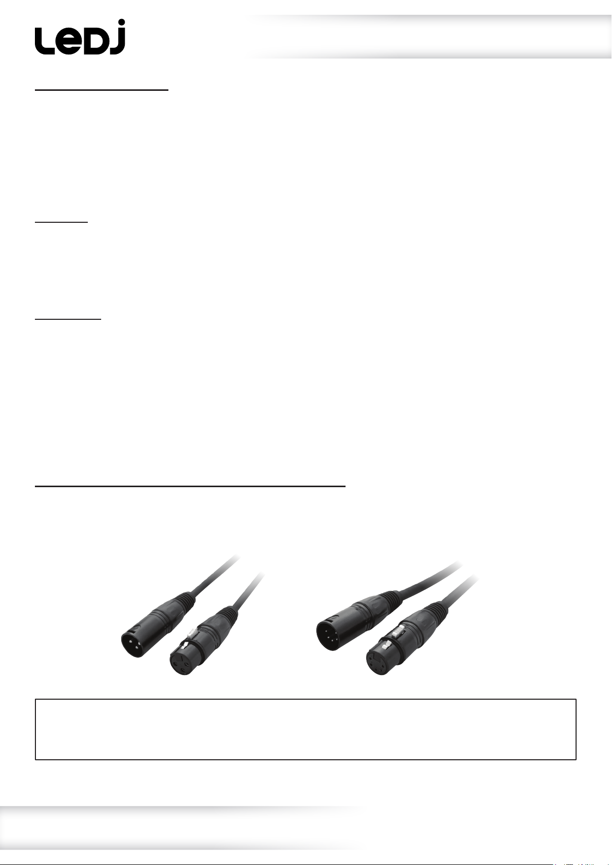
This xture can be controlled via DMX-512 protocol. The DMX address is set on the back of the unit.
Your unit requires either a standard 3-pin or 5-pin XLR connector for data input/output,
see images below.
Further DMX cables can be purchased from all good sound and lighting suppliers or Prolight Concepts dealers.
Please quote:
Also remember that DMX cable must be daisy chained and cannot be split.
CABL10 – 2m CABL11 – 5m CABL12 – 10m3-Pin:
CABL185 – 2m CABL187 – 5m CABL188 – 10m5-Pin:
www.prolight.co.uk Spectra QX40 Pixel User Manual
13
Page 14
Notice:
DMX setup
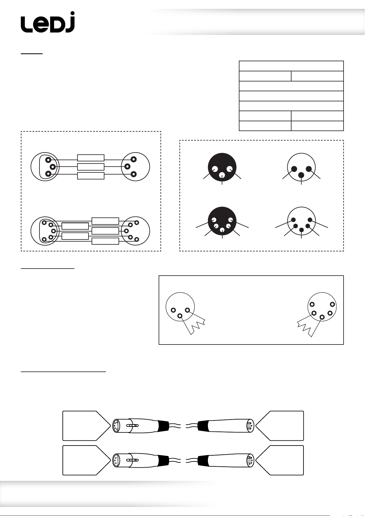
Be sure to follow the diagrams below when making your own cables.
Do not connect the cables shield conductor to the ground lug or
allow the shield conductor to come in contact with the XLRs
outer casing. Grounding the shield could cause a short circuit
and erratic behaviour.
DMX 512
3-Pin XLR output
1
3
2
DMX 512
5-Pin XLR output
1
2
3
4
5
GROUND
DMX –
N/C
DMX +
DMX –
GROUND
DMX +
N/C
DMX 512
3-Pin XLR input
1
3
2
DMX 512
5-Pin XLR input
1
2
3
4
5
3-Pin XLR male 3-Pin XLR female
1 ground
3 hot
5-Pin XLR male 5-Pin XLR female
1 ground 5 N/C
2 cold
3 hot
2 cold
4 N/C
Pin Conguration
3-Pin 5-Pin
Pin 1 - Ground
Pin 2 - Negative
Pin 3 - Positive
– Pin 4 - N/C
– Pin 5 - N/C
2 cold
5 N/C 1 ground
4 N/C
3 hot
3 hot
1 ground
2 cold
Line termination:
When longer runs of cable are used,
you may need to use a terminator on
the last unit to avoid erratic behaviour.
Using a cable terminator will decrease
the possibilities of erratic behaviour.
(3-pin - Order ref: CABL90,
3-Pin
1 2
3
Termination reduces signal
transmission problems and
interference. It is always
advisable to connect a DMX
terminal, (resistance 120
Ohm 1/4W) between pin 2
(DMX-) and pin 3 (DMX+) of
the last xture.
5-Pin
1
2 4
3
5
5-pin - Order ref: CABL89)
5-pin XLR DMX connectors:
Some manufactures use 5-pin XLR connectors for data transmission in place of 3-pin. 5-pin XLR xtures
may be implemented in a 3-pin XLR DMX line. When inserting standard 5-pin XLR connectors in to a
3-pin line a cable adaptor must be used. The diagram below details the correct cable conversion.
5-pin XLR (female)
Pin 1: GND (screen)
Pin 2: Signal (-)
Pin 3: Signal (+)
Pin 4: N/C
Pin 5: N/C
3-pin XLR (male)
Pin 1: GND (screen)
Pin 2: Signal (-)
Pin 3: Signal (+)
3-pin XLR (female)
Pin 1: GND (screen)
Pin 2: Signal (-)
Pin 3: Signal (+)
5-pin XLR (male)
Pin 1: GND (screen)
Pin 2: Signal (-)
Pin 3: Signal (+)
Pin 4: N/C
Pin 5: N/C
www.prolight.co.uk Spectra QX40 Pixel User Manual
14
Page 15
Multiple xture power linking
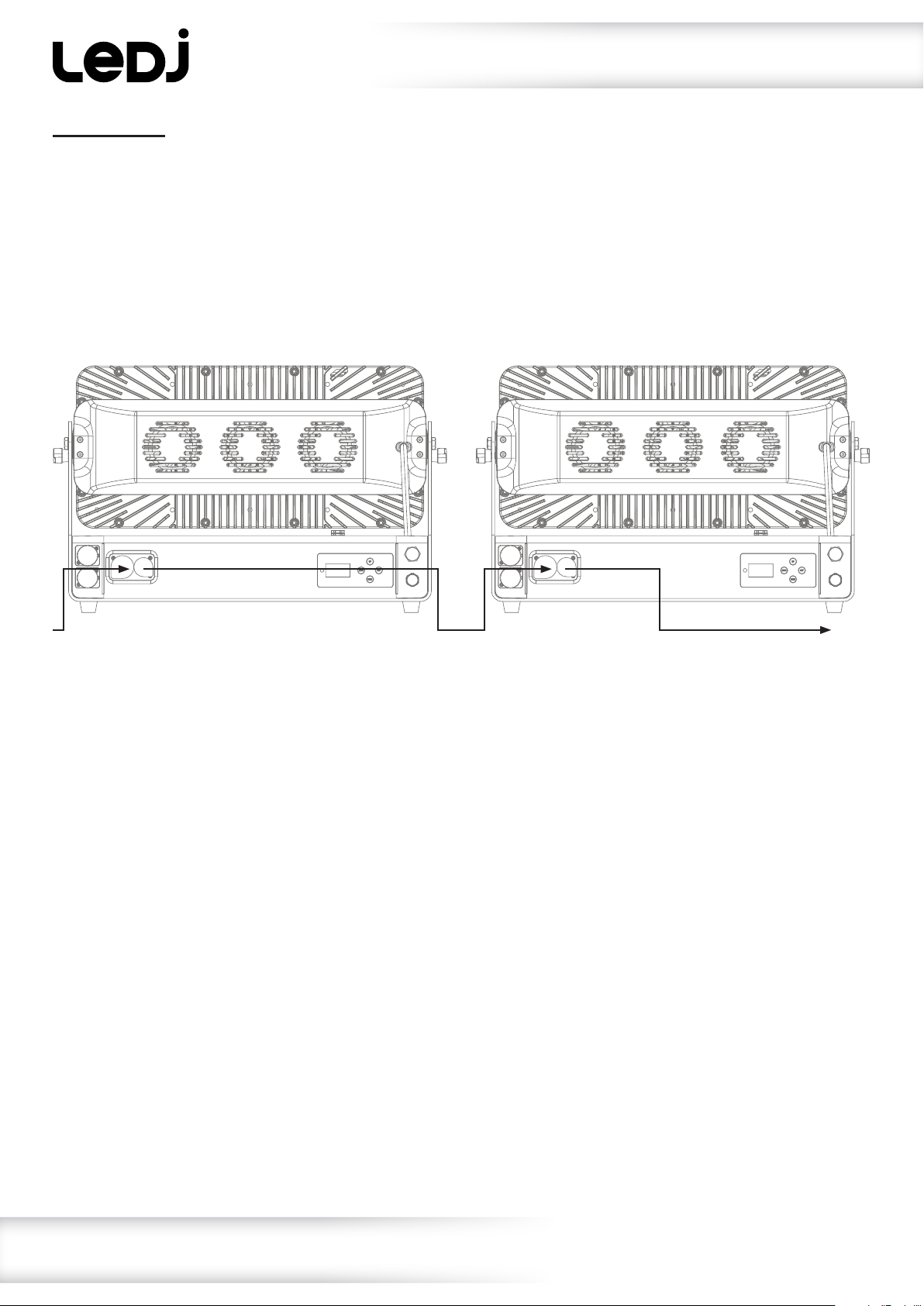
Power linking:
This xture provides power linking via the power output on the rear allowing multiple units to be
connected together. The maximum number of xtures that can be connected is 6 xtures @ 240V
or 3 xtures @ 120V (including the rst xture). After the maximum number of xtures are
connected a new power run will need to be started.
Please note: Caution should be used when power linking other xtures to the Spectra QX40 Pixel as the
power consumption of other xtures will vary. Fixtures tted with lamps often require 2/3 times more
current on startup, these may require their own power source.
www.prolight.co.uk Spectra QX40 Pixel User Manual
15
Page 16
WEEE notice
Correct Disposal of this Product
(Waste Electrical & Electronic Equipment)
(Applicable in the European Union and other European countries
with separate collection systems)
This marking shown on the product or its literature, indicates that it should not be disposed of
with other household wastes at the end of its working life. To prevent possible harm to the
environment or human health from uncontrolled waste disposal, please separate this from other
types of wastes and recycle it responsibly to promote the sustainable reuse of material resources.
Household users should contact either the retailer where they purchased this product, or their
local government ofce, for details of where and how they can take this item for environmentally
safe recycling.
Business users should contact their supplier and check the terms and conditions of the
purchase contract. This product should not be mixed with other commercial wastes for disposal.
www.prolight.co.uk Spectra QX40 Pixel User Manual
16
 Loading...