

Page 1

www.prolight.co.uk
(order code: LEDJ66)
USER MANUAL
STRATOS
Page 2

WARNING
FOR YOUR OWN SAFETY, PLEASE READ THIS USER MANUAL CAREFULLY
BEFORE YOUR INITIAL START-UP!
CAUTION!
Keep this equipment away from rain,
moisture and liquids.
SAFETY INSTRUCTIONS
Every person involved with the installation, operation & maintenance of this
equipment should:
- Be competent
- Follow the instructions of this manual
CAUTION! TAKE CARE USING THIS EQUIPMENT!
HIGH VOLTAGE-RISK OF ELECTRIC SHOCK!!
Before your initial start-up, please make sure that there is no damage caused during
transportation. Should there be any, consult your dealer and do not use the
equipment.
To maintain the equipment in good working condition and to ensure safe operation, it is necessary
for the user to follow the safety instructions and warning notes written in this manual.
Please note that damages caused by user modications to this equipment are not
subject to warranty.
STRATOS UV SAFETY
Page 3

STRATOS UV SAFETY
IMPORTANT:
The manufacturer will not accept liability for any resulting damages caused
by the non-observance of this manual or any unauthorised modication to the
equipment.
• Never let the power-cable come into contact with other cables. Handle the power-cable
and all mains voltage connections with particular caution!
• Never remove warning or informative labels from the equipment.
• Do not open the equipment and do not modify the equipment.
• Do not connect this equipment to a dimmer-pack.
• Do not switch the equipment on and off in short intervals, as this will reduce the
system’s life.
• Only use the equipment indoors.
• Do not expose to ammable sources, liquids or gases.
• Always disconnect the power from the mains when equipment is not in use or before
cleaning! Only handle the power-cable by the plug. Never pull out the plug by pulling the
power-cable.
• Make sure that the available voltage is between 220v/240v.
• Make sure that the power-cable is never crimped or damaged. Check the equipment and
the power-cable periodically.
• If the equipment is dropped or damaged, disconnect the mains power supply immediately.
Have a qualied engineer inspect the equipment before operating again.
• If the equipment has been exposed to drastic temperature uctuation (e.g. after
transportation), do not switch it on immediately. The arising condensation might damage
the equipment. Leave the equipment switched off until it has reached room temperature.
• If your product fails to function correctly, discontinue use immediately. Pack the unit
securely (preferably in the original packing material), and return it to your Prolight dealer
for service.
• Only use fuses of same type and rating.
• Repairs, servicing and power connection must only be carried out by a qualied
technician. THIS UNIT CONTAINS NO USER SERVICEABLE PARTS.
• WARRANTY; One year from date of purchase.
OPERATING DETERMINATIONS
If this equipment is operated in any other way, than those described in this manual,
the product may suffer damage and the warranty becomes void.
Incorrect operation may lead to danger e.g.: short-circuit, burns, electric shocks,
lamp failure etc.
Do not endanger your own safety and the safety of others!
Incorrect installation or use can cause serious damage to people and property.
Page 4

STRATOS UV INTRODUCTION
Introduction
CONTROL FEATURES
• 2-channel DMX-Strobe
• Blackout/Dimmer/Strobe
Features
• 336 ultra bright 10mm ultra violet LED’s
• Sound control via internal microphone
• Master/Slave functions
• Sound activated
• Rugged compact housing
• Consumption: 30w
• Beam 40 degrees
• Lamp life: 100,000 hours
OPTIONS
DMX Channel Summary
CHANNEL
CH1
CH2
VALUE
000-250
250-255
000-255
FUNCTION
DIMMING (100%)
SOUND ACTIVE
SPEED ADJUSTMENT FROM SLOW
TO FAST
Page 5
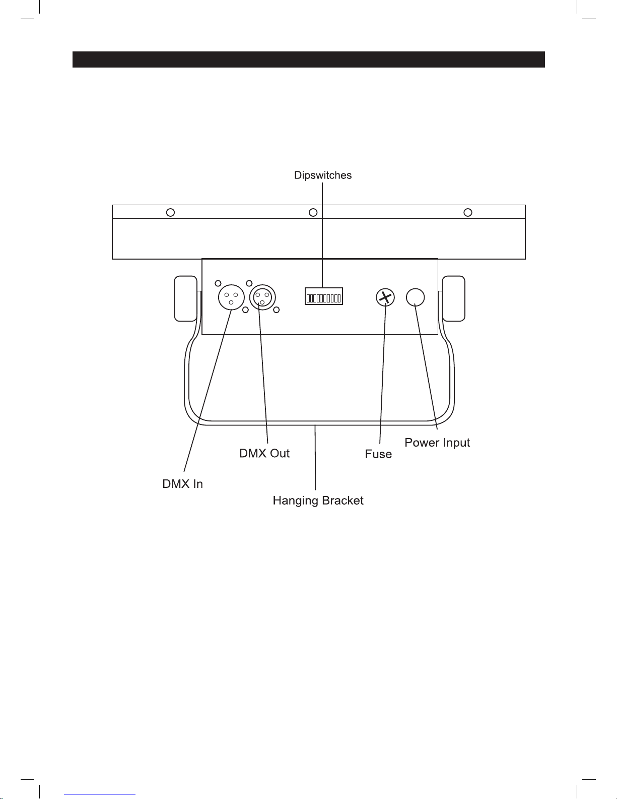
STRATOS UV OVERVIEW
Product Overview
Setup
Operating Instructions
The Stratos UV is a DMX-512 controllable, unit made up of high efciency and super bright LED’s.
The Stratos UV will operate in stand-alone, Master/Slave, sound activated or via DMX-512 control.
Page 6
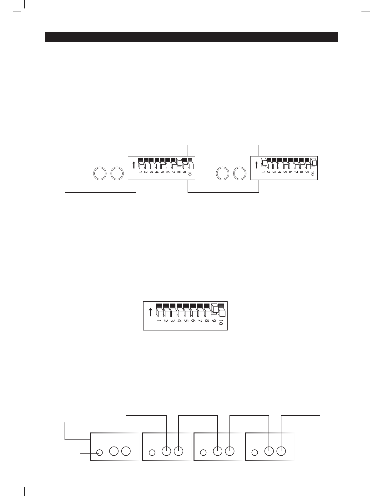
STRATOS UV MASTER/SLAVE
Master/Slave
The Master/Slave mode will allow you to link up as many units as you want in a daisy chain
fashion. In this mode, the rst unit in the daisy chain will control the following units.
1) Connect all units in a daisy chain as described in the section following.
2) For master unit in Auto mode: Set dip switch 8 to ON and all others to OFF
3) For master unit in Sound Activation mode: Set dip switch 9 to ON and all others to OFF
4) For Slave mode: set dip swiches 10+1 to ON and all others to OFF
Stand-Alone Mode
• You can run the xtures in an automatic stand-alone mode by simply setting all xtures
to run as master units. (set dip switch #8 to on and all others off).
Sound Activation
The Stratos UV has a built-in microphone which enables it to operate in Sound to Light mode. Set
the sensitivity control to the desired level, and the unit will respond to the beat of the music. Set
dip switch 9 to ON to activate Sound Mode.
Daisy Chain Connection
1) Connect the (male) 3 pin connector side of the DMX cable to the output (female) 3 pin
connector of the rst xture
2) Connect the end of the cable coming from the rst xture which will have a (female) 3 pin
connector to the input connector of the next xture consisting of a (male) 3 pin connector.
Proceed to connect from the output as stated above to the input of the following xture
and so on.
on
Dipswitches 1-8
(programmes)
IN
OUT
IN
OUT
IN
OUT
IN
OUT
INPUT FROM DMX CONTROLLER
(OPTIONAL)
AC
LINE
Continue
on
DMX512
IN OUT
on
DMX512
IN OUT
MASTER SETTING SLAVE SETTING
Page 7

STRATOS UV CONTROL OPTIONS
Manual Control Options
Dimmer
• With Dip Switch 1 only set to ON you obtain 25% output
• With Dip Switch 2 only set to ON you obtain 50% output
• With Dip Switches 1, 2 and 3 only set to ON you obtain 75% output
• With Dip Switches 1, 2, 3 and 4 only set to ON you obtain 100% output
Speed
Once you have selected the output power, you can vary the Speed by using the following:
• With Dip Switch 5 only set to ON you obtain minimum speed
• With Dip Switches 5 and 6 only set to ON you obtain medium speed
• With Dip Switches 5, 6 and 7 only set to ON you obtain fast speed
• With Dip Switches 5, 6, 7 and 8 only set to ON you obtain maximum speed
Blackout Mode
With only dipswitch #10 + 1 set to ON the Stratos will blackout.
DMX Control Mode
Operating in a DMX control mode environment gives the user the greatest exibility when it comes
to customising or creating a show. In this mode you will be able to control each individual trait of
the xture and each xture independently. The Sratos uses 2 channels of control.
Enable the DMX control by setting dipswitch No: 10 to the ON position. Use dipswitches 1 – 9 to
address each xture accordingly.
Setting the DMX address
The DMX mode enables the use of a universal DMX controller. Each xture requires a “start
address” from 1- 511. A xture requiring one or more channels for control begins to read the data
on the channel indicated by the start address. For example, a xture that occupies or uses 7
channels of DMX and was addressed to start on DMX channel 100, would read data from
channels: 100,101,102,103,104,105 and 106. Choose a start address so that the channels used
do not overlap. E.g. the next unit in the chain starts at 107.
Page 8
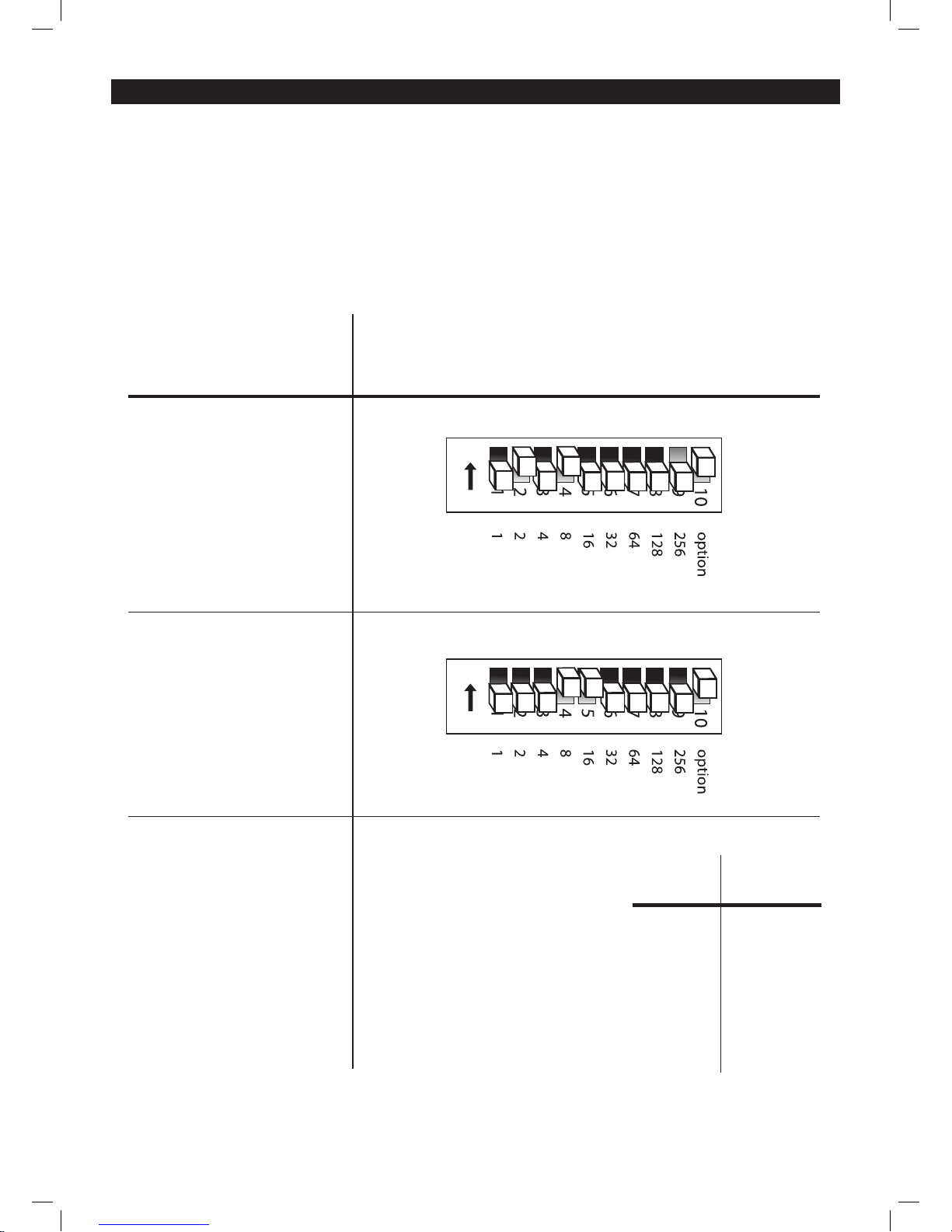
STRATOS UV CONTROL OPTIONS
Set the start address using the group of dip switches located usually on the back of the xture.
Each dipswitch has an associated value. Adding the value of each switch in the ON position will
provide the start address. Determining which switches to toggle ON given a specic start address
can be accomplished in the following manner. By subtracting the largest switch value possible
from the selected start address until zero is achieved.
on
on
EXAMPLE STARTING ADDRESS
Address 10
Pin NO: 4 = 8
Pin NO: 2 = 2
Total = 10
Address 24
Pin NO: 5 = 16
Pin NO: 4 = 8
Total = 24
DMX address using
simple maths
233 - (128 = 105, Turn on dip No: 8
105 - (64) = 41, Turn on dip No:7
41 - (32) = 9, Turn on dip No: 6
9 - (8) = 1, Turn on dip No: 4
1 - (1) = 0, Turn on dip No:1
You will most likely use the first available
number which maybe Number 1. This
number was selected for
example purposes
DIP SWITCH (DMX VALUE)
1
2
3
4
5
6
7
8
9
10
1
2
4
8
16
32
64
128
256
Page 9
STRATOS UV DMX SET UP
DMX-512:
• DMX (Digital Multiplex) is a universal protocol used as a form of communication between
intelligent xtures and controllers. A DMX controller sends DMX data instructions form the
controller to the xture. DMX data is sent as serial data that travels from xture to xture via the
DATA “IN” and DATA “OUT” XLR terminals located on all DMX xtures (most controllers only
have a data “out” terminal).
DMX Linking:
• DMX is a language allowing all makes and models of different manufactures to be linked together
and operate from a single controller, as long as all xtures and the controller are DMX compliant.
To ensure proper DMX data transmission, when using several DMX xtures try to use the
shortest cable path possible. The order in which xtures are connected in a DMX line does not
inuence the DMX addressing. For example; a xture assigned to a DMX address of 1 may be
placed anywhere in a DMX line, at the beginning, at the end, or anywhere in the middle. When a
xture is assigned a DMX address of 1, the DMX controller knows to send DATA assigned to
address 1 to that unit, no matter where it is located in the DMX chain.
DATA Cable (DMX cable) requirements (for DMX operation):
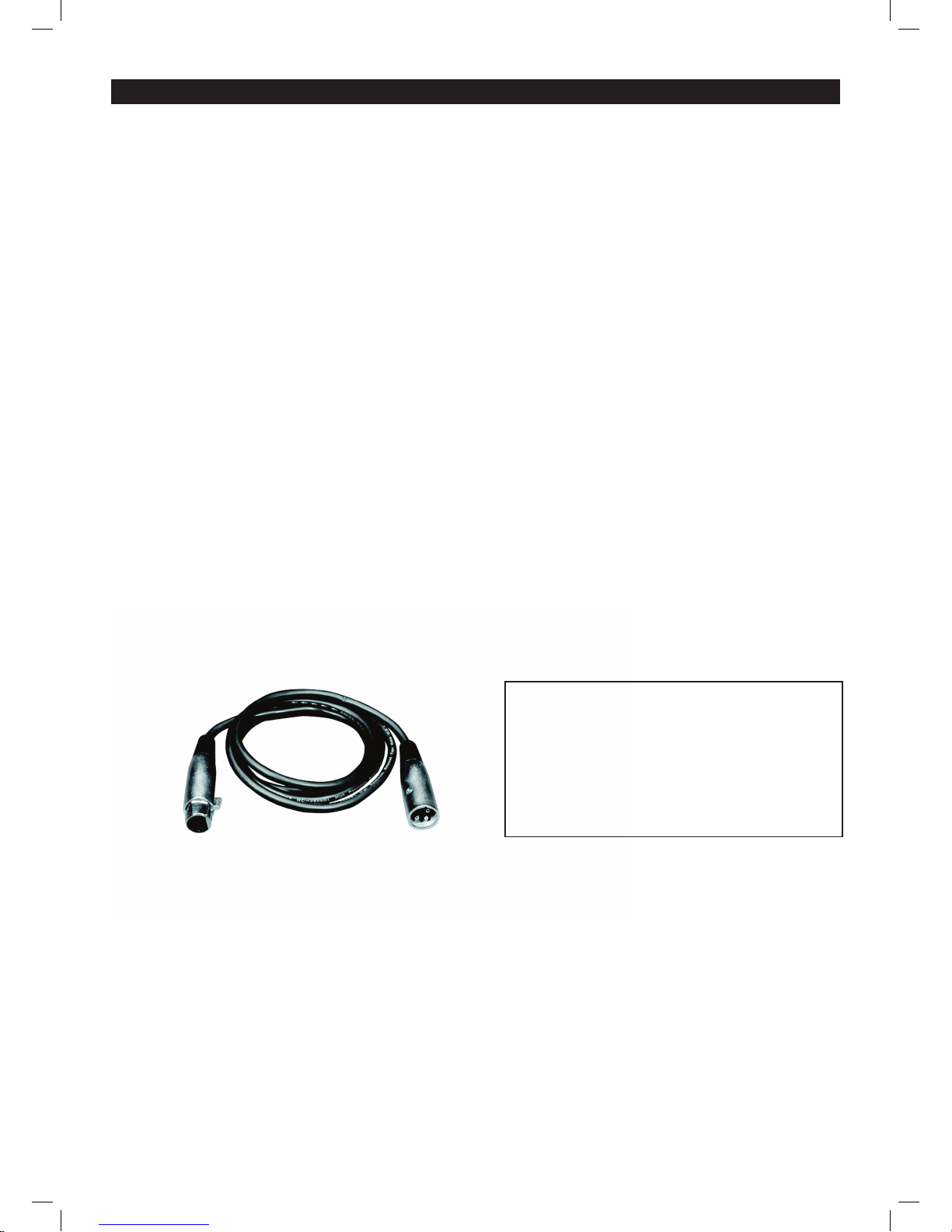
• The Stratos UV can be controlled via DMX-512 protocol. The DMX address is set on the
back of the unit. Your unit and your DMX controller require a standard 3-pin XLR connector for
data input/output (gure 1).
Figure 1
Also remember that DMX cable must be daisy chained and cannot be split.
Further DMX cables can be purchased from all
good sound and lighting suppliers or Prolight
dealers.
Please quote:
CABL10 – 2M
CABL11 – 5M
CABL12 – 10M
Page 10
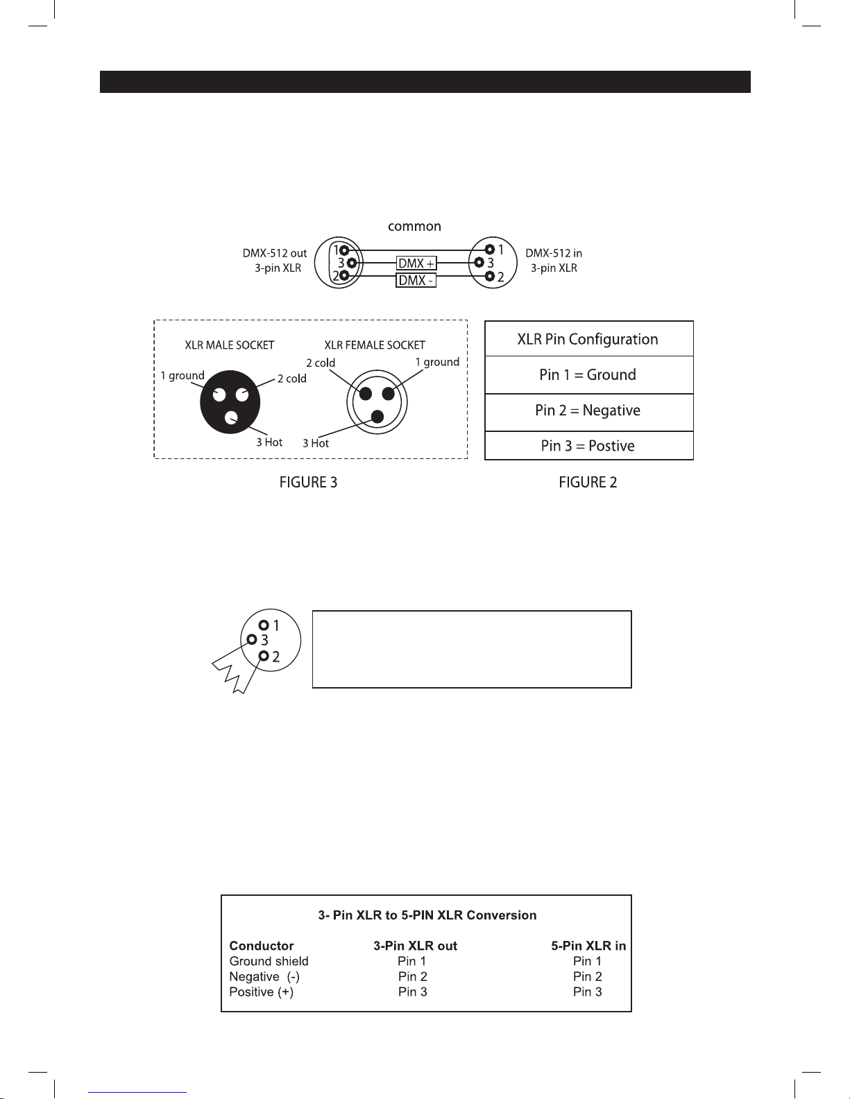
Notice:
• Be sure to follow gures 2 & 3 when making your own cables. Do not connect the cable’s shield
conductor to the ground lug or allow the shield conductor to come in contact with the XLR’s outer
casing. Grounding the shield could cause a short circuit and erratic behaviour.
Special Note: Line termination:
• When longer runs of cable are used, you may need to use a terminator on the last unit to
avoid erratic behaviour.
Using a cable terminator (part number CABL90) will decrease the possibilities of erratic
behaviour.
5-Pin XLR DMX Connectors:
• Some manufactures use 5-pin XLR connectors for data transmission in place of 3-pin. 5-Pin
XLR xtures may be implemented in a 3-pin XLR DMX line. When inserting standard 5-pin
XLR connectors in to a 3-pin line a cable adaptor must be used. The chart below details the
correct cable conversion.
Termination reduces signal transmission problems
and interferance. it is always advisable to connect a
DMX terminal, (resistance 120 Ohm 1/4 W) between
pin 2 (DMX-) and pin 3 (DMX+) of the last fixture.
STRATOS UV DMX SET UP
Page 11
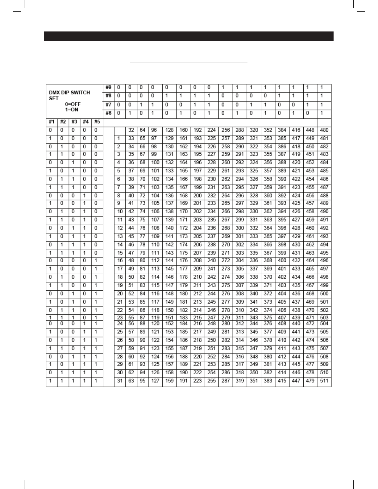
STRATOS UV Dip Switch Reference Chart
DMX Dip Switch Quick Reference Chart
Dip Switch Position
Page 12

STRATOS UV DMX VALUES
Technical Specications
Weight & Dimensions
• Length…...........................................................382mm
• Width................................................................105mm
• Height……………………………………………..215mm
• Weight……………………………………….........2.5kgs
Power
• AC input……………………………………..........230V/50hz
Fuse
• Main……………………………………………….20mm Glass 0.5A Fast Blow
Control & Programming
• Data input………………………………………...Locking 3-pin XLR male socket
• Data output……………………………………….Locking 3-pin XLR female socket
• Protocols…………………………………………DMX-512 UTSITT
• DMX channels…………………………………...2
 Loading...