

Page 1

w w w . p r o l i g h t . c o . u k
LEDJ Xterior Wash
Order code: LEDJ131 (1W - Silver)
Order code: LEDJ132 (1W - Black)
Order code: LEDJ133 (3W - Silver)
Order code: LEDJ134 (3W - Black)
USER MANUAL
Page 2
WARNING
FOR YOUR OWN SAFETY, PLEASE READ THIS USER MANUAL CAREFULLY
BEFORE YOUR INITIAL START-UP!
CAUTION!
THIS UNIT ONLY ACCEPTS AN
INPUT VOLTAGE OF 240V
SAFETY INSTRUCTIONS
Every person involved with the installation, operation & maintenance of this
equipment should:
- Be competent
- Follow the instructions of this manual
CAUTION! TAKE CARE USING THIS EQUIPMENT!
HIGH VOLTAGE-RISK OF ELECTRIC SHOCK!!
Before your initial start-up, please make sure that there is no damage caused during
transportation. Should there be any, consult your dealer and do not use the
equipment.
To maintain the equipment in good working condition and to ensure safe operation, it is necessary
for the user to follow the safety instructions and warning notes written in this manual.
Please note that damages caused by user modications to this equipment are not
subject to warranty.
Xterior Wash Safety
Page 3

Xterior Wash Safety
IMPORTANT:
The manufacturer will not accept liability for any resulting damages caused
by the non-observance of this manual or any unauthorised modication to the
equipment.
• Never let the power-cable come into contact with other cables. Handle the power-cable
and all mains voltage connections with particular caution!
• Never remove warning or informative labels from the equipment.
• Do not open the equipment and do not modify the equipment.
• Do not connect this equipment to a dimmer-pack.
• Do not switch the equipment on and off in short intervals, as this will reduce the
system’s life.
• Do not expose to ammable sources or gases.
• Always disconnect the power from the mains when equipment is not in use or before
cleaning! Only handle the power-cable by the plug. Never pull out the plug by pulling the
power-cable.
• Make sure that the available voltage is between 220v/240v.
• Make sure that the power-cable is never crimped or damaged. Check the equipment and
the power-cable periodically.
• If the equipment is dropped or damaged, disconnect the mains power supply immediately.
Have a qualied engineer inspect the equipment before operating again.
• If your product fails to function correctly, discontinue use immediately. Pack the unit
securely (preferably in the original packing material), and return it to your Prolight dealer
for service.
• Only use fuses of same type and rating.
• Repairs, servicing and power connection must only be carried out by a qualied
technician. THIS UNIT CONTAINS NO USER SERVICEABLE PARTS.
• WARRANTY; One year from date of purchase.
OPERATING DETERMINATIONS
If this equipment is operated in any other way, than those described in this manual,
the product may suffer damage and the warranty becomes void.
Incorrect operation may lead to danger e.g.: short-circuit, burns, electric shocks,
lamp failure etc.
Do not endanger your own safety and the safety of others!
Incorrect installation or use can cause serious damage to people and property.
Page 4
You should nd inside the LEDJ carton the following items:
1, Xterior Wash Unit 2, Instruction manual
Technical Specications:
400Hz icker free 1W or 3W LEDs
Voltage: AC 240 ~ 50Hz
36 Ultra bright 1W LEDs (R: 12, G: 12, B: 12)
36 Ultra bright 3W LEDs (R: 12, G: 12, B: 12)
Power Consumption: 50W - 1W
150W - 3W
Beam angle: 40 degrees
Dimensions: 220 x 220 x 280mm
Weight: 6.4Kgs
Operating modes: 1, Static Colour mode
2, Colour change mode
3, Colour Fade mode
4, Slave mode
5, DMX channels: 6
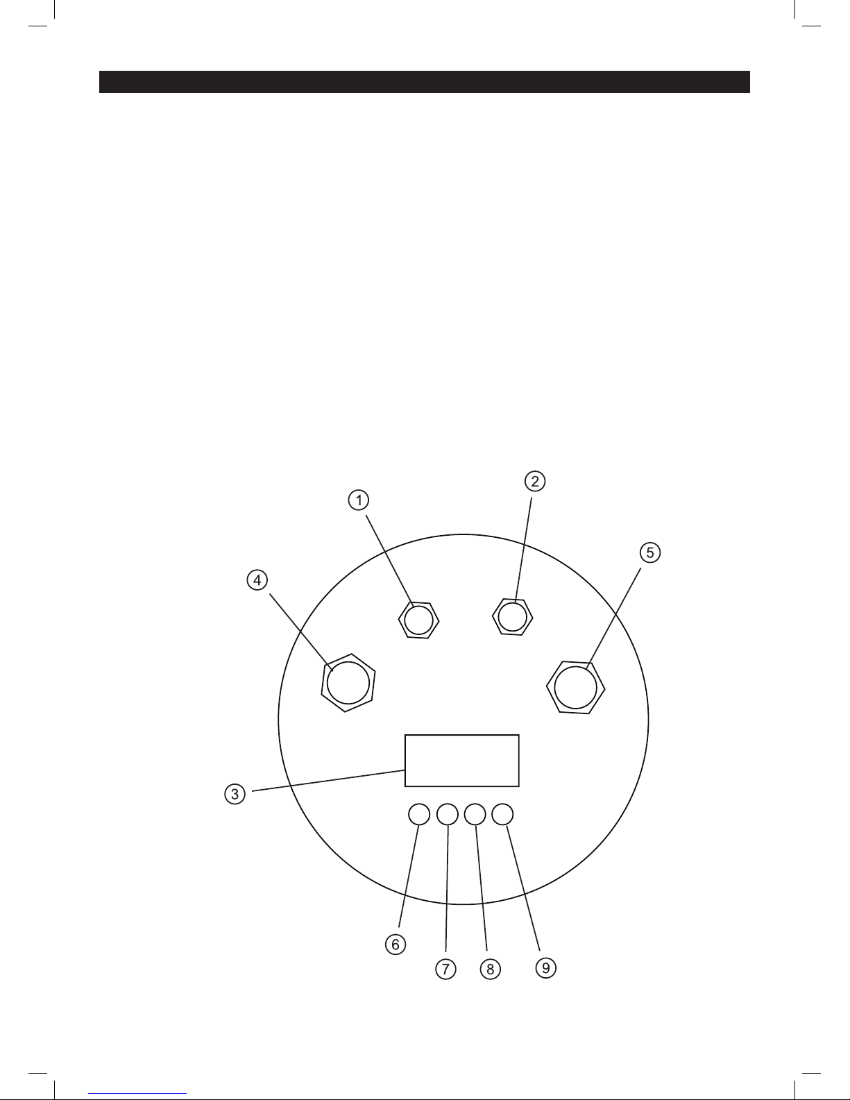
Overview:
1, DMX input
2, DMX output
3, LED display
4, Power input
5, Power output
6, Mode selection button
7, Set up button
8, Function up button
9, Function down button
Xterior Wash Technical specications
POWER
INPUT
DMX IN DMX OUT
POWER
OUTPUT
Page 5
There are 5 different operation modes to choose from:
1) Static colour mode 2) Colour change mode 3) Colour fade mode
4) Slave mode 5) DMX mode
1, Static colour mode
Mode button - Press the “MODE” button under the LED display, to show “C000”, then press the
“SET UP” button to choose one of the static colours using the “UP” and “DOWN” buttons.
The Colours range from:
1, “C100” = RED, 2, “C200” = Green, 3, “C300” = Blue, 4, “CF00” = Strobe
Now press the “SET UP” button again and you can then select the brightness output using the
“UP” and “DOWN” buttons.
The light output settings are from 00-99 (00 = off, 99 = full)
The strobe speed settings are from 00-99 (00 = slow, 99 = fast)
2, Colour change mode
Mode button - Press the MODE button until the LED display shows “J000”, then press the “SET
UP” button to choose one of the colour changing modes using the “UP” and “DOWN” buttons.
The colour change programmes are as follows:
1, “J300” = RGB, 2, “J700” = 7 colour, 3, “JF00” = Strobe,
Now press the “SET UP” button again and you can then select the colour change speed using the
“UP” and “DOWN” buttons.
The speed settings are from 00-99 (00 = slow, 99 = fast)
3, Colour fade mode
Mode button - Press the MODE button until the LED display shows “F000”, then press the “SET
UP” button to choose one of the colour changing modes using the “UP” and “DOWN” buttons.
The colour fade programmes are as follows:
1, “F300” = RGB, 2, “F700” = 7 colour, 3, “FF00” = Strobe,
Now press the “SET UP” button again and you can then select the colour fade speed using the
“UP” and “DOWN” buttons.
The speed settings are from 00-99 (00 = slow, 99 = fast)
4). Slave mode
Link the units together using a 4-pin DMX cable, then press the MODE button to select one of the
above modes. On the Slave units press the mode button until the LED display shows “SLAV”. The
Slave units will then follow in sequence with the Master unit.
5). DMX Addressing mode
To access the DMX address mode, press the MODE button until the LED display shows “A000”,
then press the “SET UP” button and set the rst digit in the DMX address using the “UP” and
“DOWN” buttons. Now repeat this step to set the second and third digits for the desired DMX
address setting. Follow the DMX channel assignment and function table overleaf.
Note: Always press the “SET UP” button a fourth time to conrm the setting in each
of the above modes.
Xterior Wash Operation
Page 6
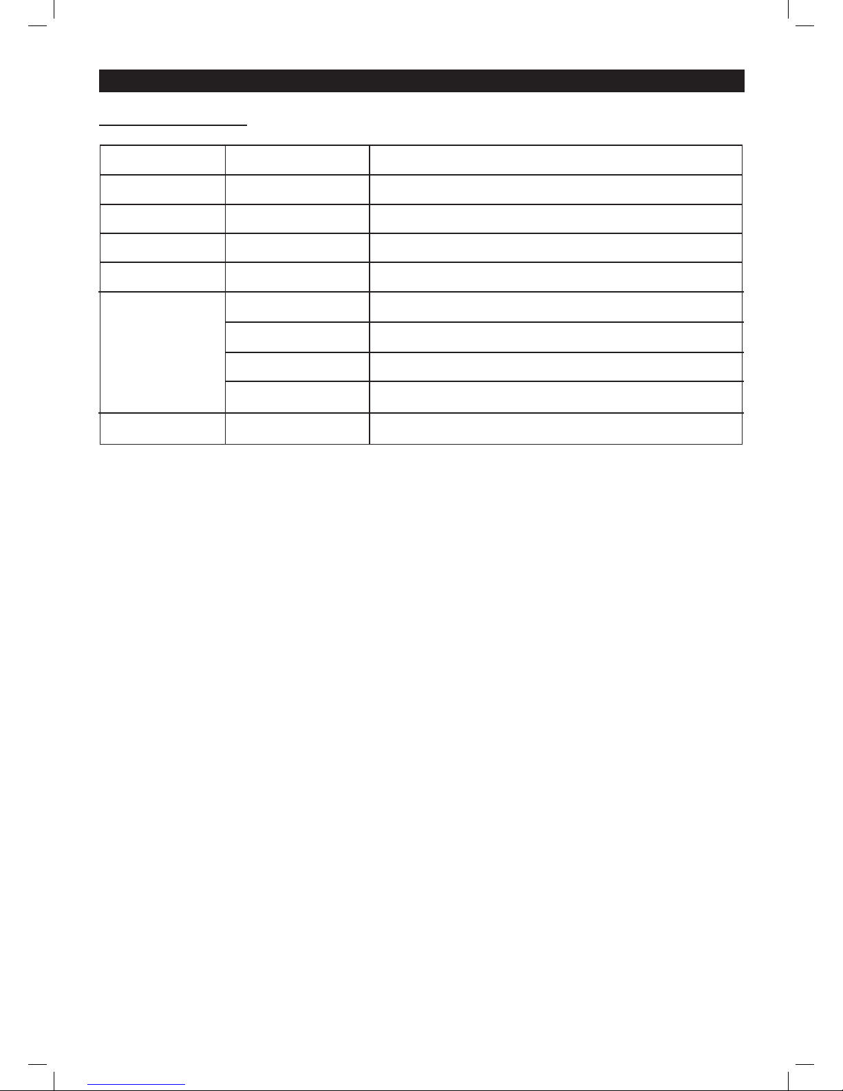
6 Channel DMX chart
Xterior Wash Operation
Channel
1
2
3
4
5
6
Value
000-255
000-255
000-255
000-255
0-4
5-84
85-169
170-255
0-255
Function
Master dimmer
Red (0 - 100%)
Green (0 - 100%)
Blue (0-100%)
Blackout
Colour macro
Colour change
Colour fade
Strobe
Page 7

Page 8

www.prolight.co.uk
 Loading...