

Page 1
www.prolight.co.uk
COLOR BURST SOUND ACTIVE
(order code: LEDJ01)
USER MANUAL
Page 2
LEDJ COLOR BURST SAFETY
WARNING
FOR YOUR OWN SAFETY, PLEASE READ THIS USER MANUAL CAREFULLY
BEFORE YOUR INITIAL START-UP!
Keep this equipment away from rain,
CAUTION!
moisture and liquids.
SAFETY INSTRUCTIONS
Every person involved with the installation, operation & maintenance of this
equipment should:
- Be competent
- Follow the instructions of this manual
CAUTION! TAKE CARE USING THIS EQUIPMENT!
HIGH VOLTAGE-RISK OF ELECTRIC SHOCK!!
Before your initial start-up, please make sure that there is no damage caused during
transportation. Should there be any, consult your dealer and do not use the equipment.
To maintain the equipment in good working condition and to ensure safe operation, it is
necessary for the user to follow the safety instructions and warning notes written in this
manual.
Please note that damages caused by user modifications to this equipment are not
subject to warranty.
Page 3

LEDJ COLOR BURST SAFETY
IMPORTANT:
The manufacturer will not accept liability for any resulting damages caused
by the non-observance of this manual or any unauthorised modification to the
equipment.
• Never let the power-cable come into contact with other cables. Handle the
power-cable and all mains voltage connections with particular caution!
• Never remove warning or informative labels from the equipment.
• Do not open the equipment and do not modify the equipment.
• Do not connect this equipment to a dimmer-pack.
• Do not switch the equipment on and off in short intervals, as this will
reduce the system’s life.
• Only use the equipment indoors.
• Do not expose to flammable sources, liquids or gases.
• Always disconnect the power from the mains when equipment is not in
use or before cleaning! Only handle the power-cable by the plug. Never
pull out the plug by pulling the power-cable.
• Make sure that the available voltage is between 220v/240v.
• Make sure that the power-cable is never crimped or damaged. Check the
equipment and the power-cable periodically.
• If the equipment is dropped or damaged, disconnect the mains power supply
immediately. Have a qualified engineer inspect the equipment before
operating again.
• If the equipment has been exposed to drastic temperature fluctuation (e.g.
after transportation), do not switch it on immediately. The arising
condensation might damage the equipment. Leave the equipment switched
off until it has reached room temperature.
• If your product fails to function correctly, discontinue use immediately. Pack
the unit securely (preferably in the original packing material), and return it to
your Prolight dealer for service.
• Only use fuses of same type and rating.
• Repairs, servicing and power connection must only be carried out by a
qualified technician. THIS UNIT CONTAINS NO USER SERVICEABLE
PARTS.
• WARRANTY; One year from date of purchase.
OPERATING DETERMINATIONS
If this equipment is operated in any other way, than those described in this manual, the
product may suffer damage and the warranty becomes void.
Incorrect operation may lead to danger e.g.: short-circuit, burns, electric shocks,
lamp failure etc.
Do not endanger your own safety and the safety of others!
Incorrect installation or use can cause serious damage to people and property!
Page 4
LEDJ COLOR BURST INTRODUCTION
Introduction
Features
CONTROL FEATURES
• 4-channel DMX-512 LED Par Can
• Blackout/Dimmer/Strobe
• Sound Active
• Individual control of Red, Green and Blue LED’s
Features
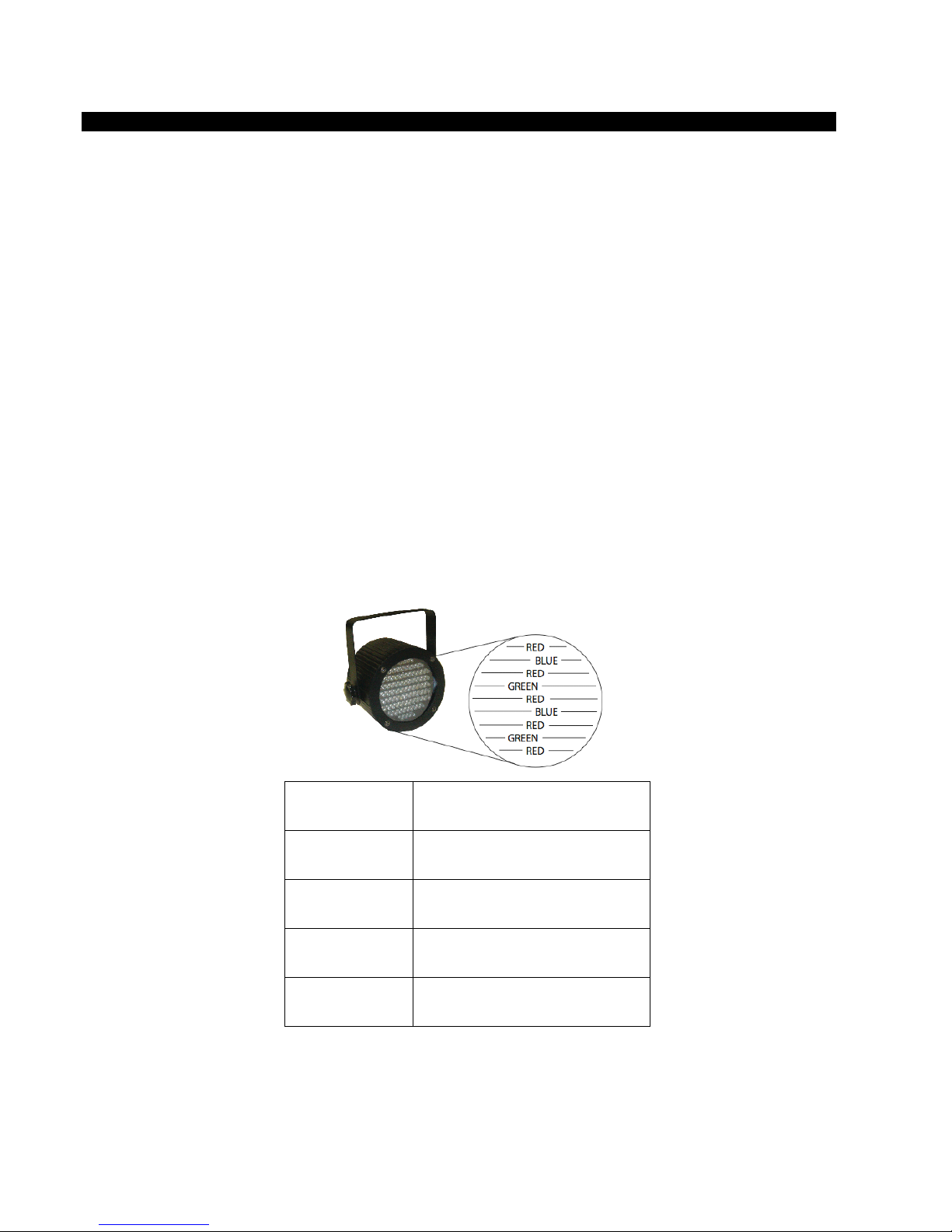
• 86 LED’s :- Red (44), Green (21), and Blue (21)
• Ultra bright LED’s
• RGB colour mixing
• Built-in colour change programs
• Power consumption: 10W
• Up to 100,000-hour LED life span
• Master/Slave mode
• Programmable: Any universal DMX-512 controller
DMX Channel Summary
CHANNEL
1
2
3
4
FUNCTION
BLACKOUT/STROBE/DIMMER
RED
GREEN
BLUE
Page 5
LEDJ COLOR BURST OVERVIEW
Product Overview
Operating Instructions
The Colour Burst is a DMX-512 controllable, full RGB colour mixing Par Can made up of high
efficiency and super bright LED’s. There are three colour groups (red, blue and green) whose
intensity can be controlled individually allowing the creation of an unlimited range of colours.
The Colour Burst can operate in stand-alone, Master/Slave, Sound Active and via DMX-512
control utilizing 4 channels.
Page 6
LEDJ COLOR BURST OPERATING INSTRUCTIONS
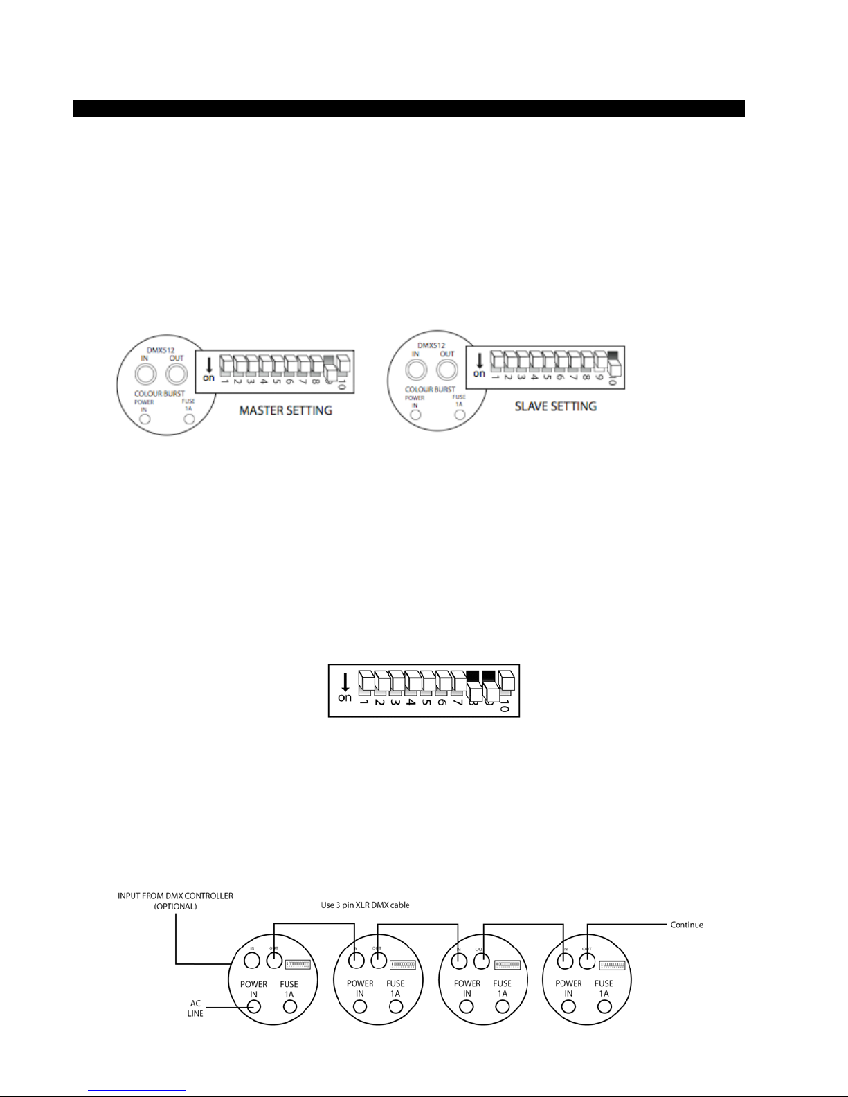
Master/Slave
The Master/Slave mode will allow you to link up as many units as you want in a daisy chain
fashion. In this mode, the first unit in the daisy chain will automatically command the slave units:
1) Connect all units in a daisy chain fashion as described in the section following
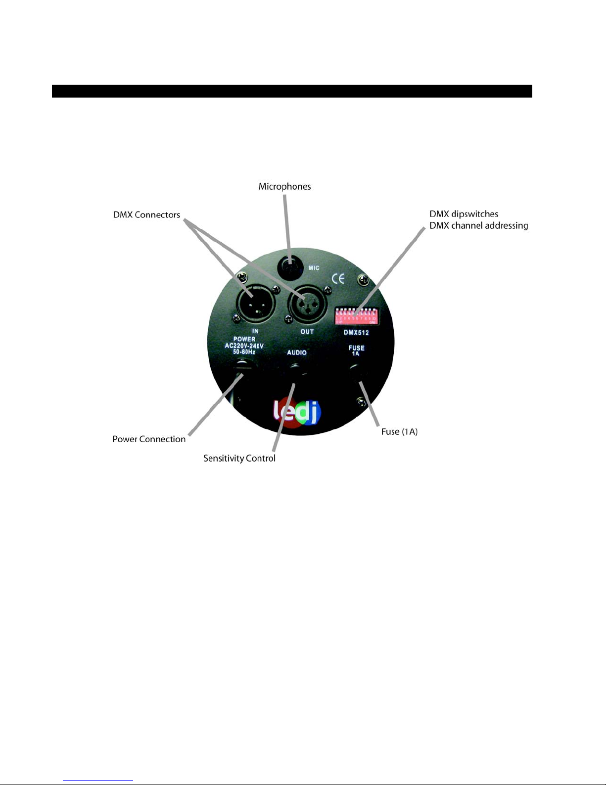
2) Master Unit: Set dipswitch No: 9 to on and No: 10 to off.
3) Slaves: Set dipswitch No: 10 to the on position and all others to the off position
Stand-Alone Mode
You can run the fixtures in an automatic stand-alone mode by simply setting all fixtures
to run as master units without daisy chaining.
Sound Activation
The LED Par Can has a built-in microphone which enables it to operate in Sound to Light mode.
Set the sensitivity control to the desired level, and the Color Burst will change colour to the beat
of the music. Set dip switch 8+9 to ON to activate S ou nd Mod e .
Daisy Chain Connection
1) Connect the (male) 3 pin connector side of the DMX cable to the output (female) 3 pin
connector of the first fixture
2) Connect the end of the cable coming from the first fixture which will have a (female) 3 pin
connector to the input connector of the next fixture consisting of a (male) 3 pin connector.
Proceed to connect from the output as stated above to the input of the following fixture
and so on.
Page 7
LEDJ COLOR BURST BUILT-IN OPTIONS
Built-in Program Options
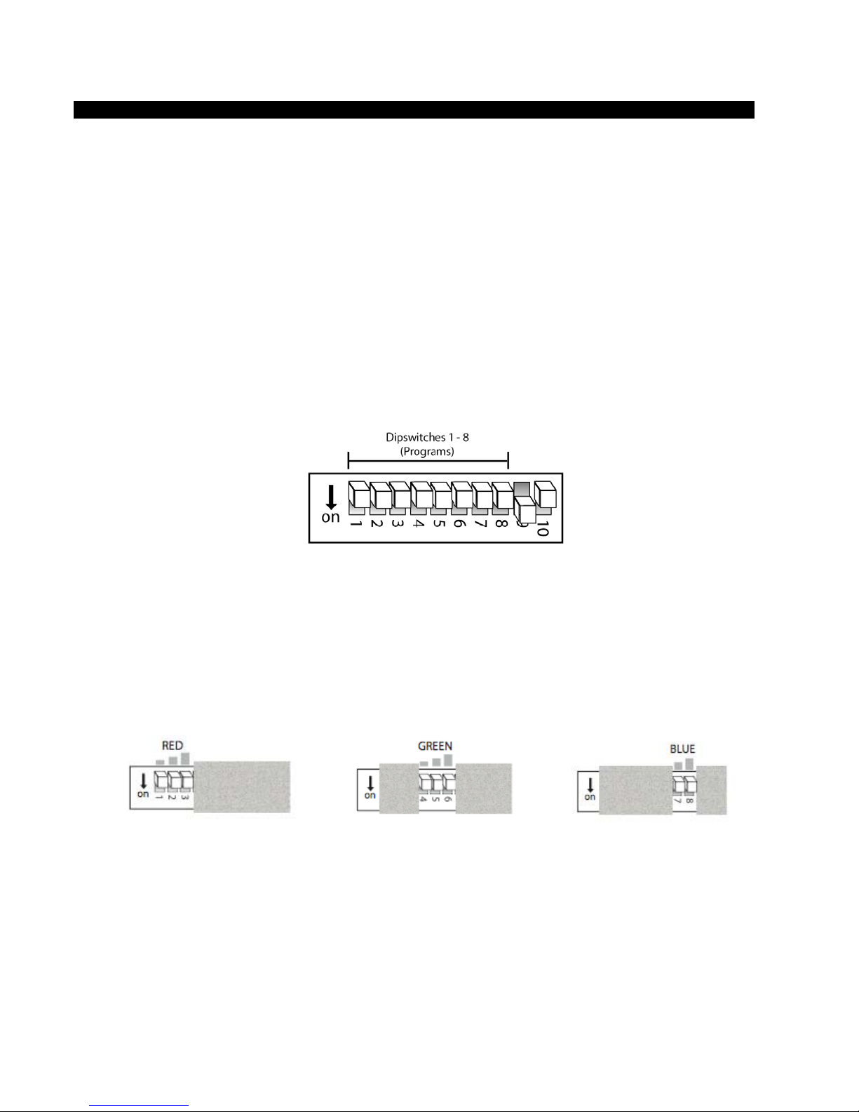
In this mode it is possible to access various in-built programs & control the speed of them.
Firstly set the dip switch #9 to ON position & #10 to OFF
Dip switches #1 – 3 adjust the program selection. By selecting a combination of ON or OFF
different patterns will be produced.
Dip switches #4 – 8 controls the speed of these patterns.
#4 ON = Very Fast
#5 ON = Fast
#6 ON = Medium
#7 ON = Slow
#8 ON = Very Slow.
Manual Control Options
With all the dipswitches set to the off position, the dipswitches 1 – 8 will control 3 levels of
intensity for red and green LED’s and 2 levels of intensity for blue LED’s.
This allows you to statically set a colour of preference without the use of a controller. By setting
different intensities for all 3 LED colours you can compose a colour of your choice.
Manual Intensity Control RGB Mix
DMX Control Mode
Operating in a DMX control mode environment gives the user the greatest flexibility when it
comes to customising or creating a show. In this mode you will be able to control each individual
trait of the fixture and each fixture independently. The Colour Burst uses 4 channels of control.
Enable the DMX control by setting dipswitch No: 10 to the ON position. Use dipswitches 1 – 9 to
address each fixture accordingly.
Page 8
LEDJ COLOR BURST OPERATING INSTRUCTIONS
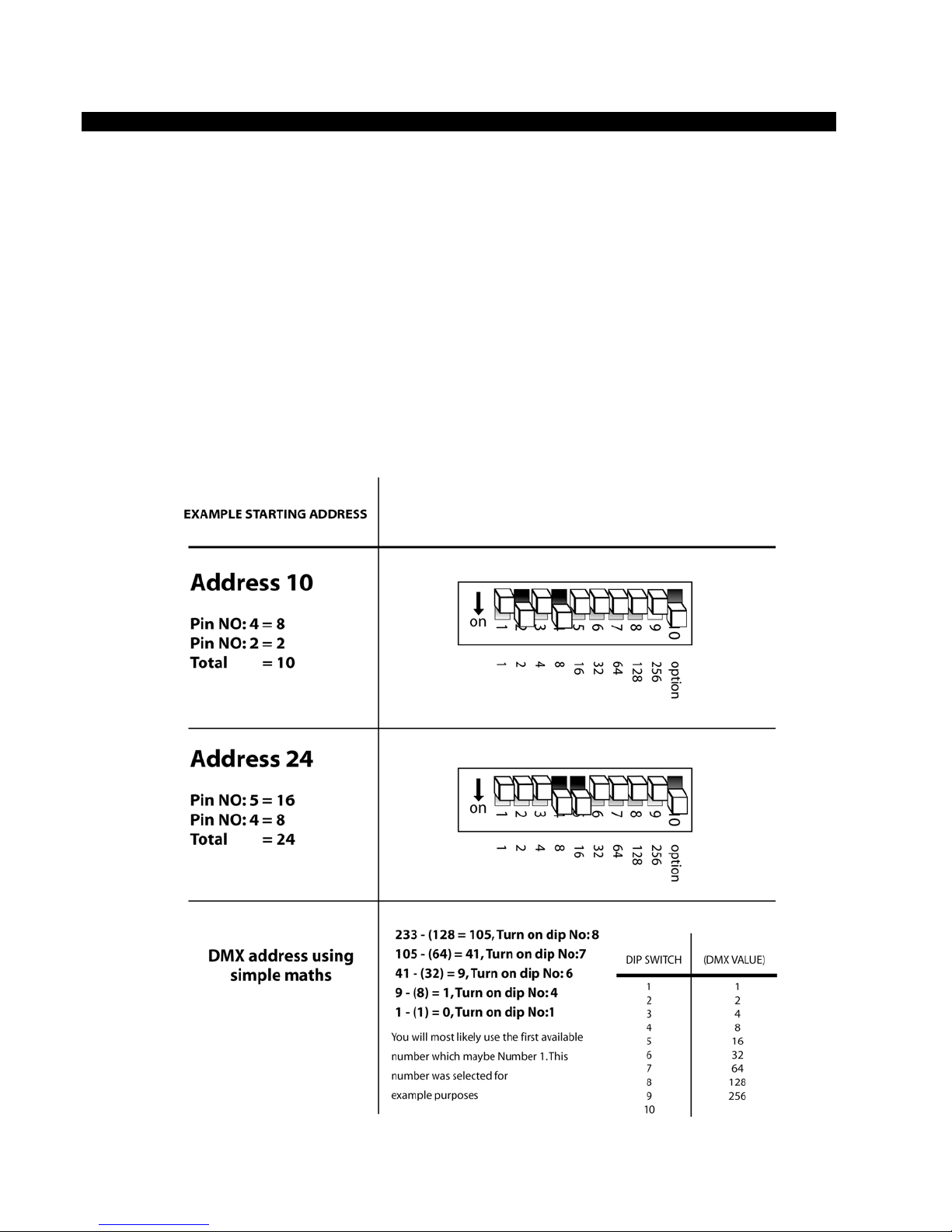
Setting the DMX address
The DMX mode enables the use of a universal DMX controller. Each fixture requires a “start
address” from 1- 511. A fixture requiring one or more channels for control begins to read the
data on the channel indicated by the start address. For example, a fixture that occupies or uses
7 channels of DMX and was addressed to start on DMX channel 100, would read data from
channels: 100,101,102,103,104,105 and 106. Choose a start address so that the channels used
do not overlap. E.g. the next unit in the chain starts at 107.
Set the start address using the group of dipswitches located usually on the bottom of the fixture.
Each dipswitch has an associated value. Adding the value of each switch in the ON position will
provide the start address. Determining which switches to toggle ON given a specific start
address can be accomplished in the following manner. By subtracting the largest switch value
possible from the selected start address until zero is achieved.
Page 9
LEDJ COLOR BURST DMX SET UP
DMX-512:
• DMX (Digital Multiplex) is a universal protocol used as a form of communication
between intelligent fixtures and controllers. A DMX controller sends DMX data
instructions from the controller to the fixture. DMX data is sent as serial data that
travels from fixture to fixture via the DATA “IN” and DATA “OUT” XLR terminals
located on all DMX fixtures (most controllers only have a data “out” terminal).
DMX Linking:
• DMX is a language allowing all makes and models of different manufactures to
be linked together and operate from a single controller, as long as all fixtures and
the controller are DMX compliant. To ensure proper DMX data transmission,
when using several DMX fixtures try to use the shortest cable path possible. The
order in which fixtures are connected in a DMX line does not influence the DMX
addressing. For example; a fixture assigned to a DMX address of 1 may be
placed anywhere in a DMX line, at the beginning, at the end, or anywhere in the
middle. When a fixture is assigned a DMX address of 1, the DMX controller
knows to send DATA assigned to address 1 to that unit, no matter where it is
located in the DMX chain.
DATA Cable (DMX cable) requirements (for DMX operation):
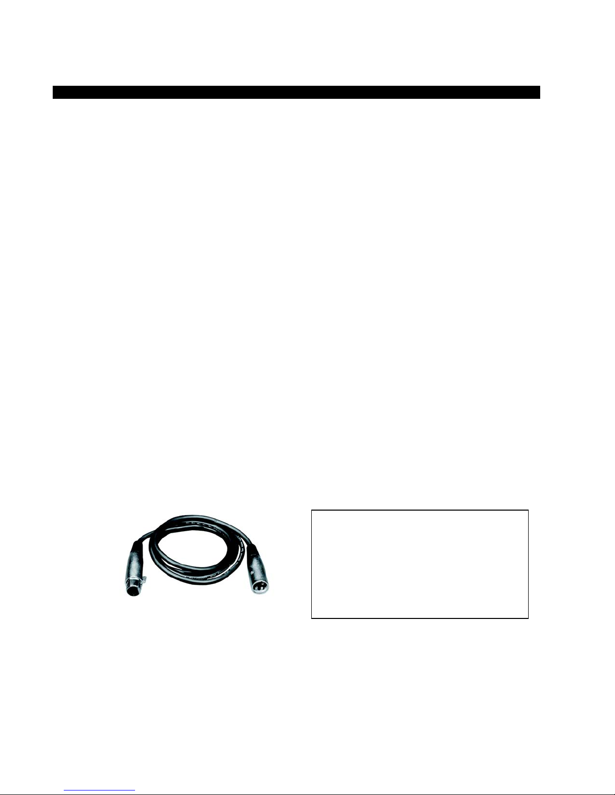
• The LEDJ Color Burst can be controlled via DMX-512 protocol. The DMX
address is set on the back of the unit. Your unit and your DMX controller require
a standard 3-pin XLR connector for data input/output (figure 1).
Figure 1
Also remember that DMX cable must be daisy chained and
cannot be split.
Further DMX cables can be
purchased from all good sound and
lighting suppliers or Prolight dealers.
Please quote:
CABL10 – 2M
CABL11 – 5M
CABL12 – 10M
Page 10
LEDJ COLOR BURST DMX SET UP
Notice:
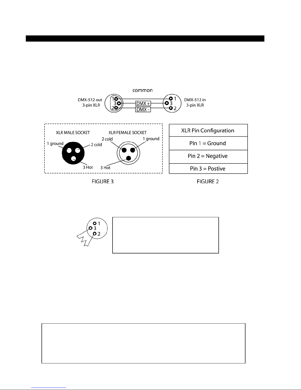
• Be sure to follow figures 2 & 3 when making your own cables. Do not connect
the cable’s shield conductor to the ground lug or allow the shield conductor to
come in contact with the XLR’s outer casing. Grounding the shield could cause a
short circuit and erratic behaviour.
Special Note: Line termination:
• When longer runs of cable are used, you may need to use a terminator on the
last unit to avoid erratic behaviour.
Termination reduces signal transmission
problems and interference. It is always advisable
to connect a DMX terminal, (resistance 120
Ohm 1/4W) between Pin 2 (DMX-) and Pin 3
(DMX+) of the last fixture
Figure 4
Using a cable terminator (part number CABL90) will decrease the
possibilities of erratic behaviour.
5-Pin XLR DMX Connectors:
• Some manufactures use 5-pin XLR connectors for data transmission in place of
3-pin. 5-Pin XLR fixtures may be implemented in a 3-pin XLR DMX line. When
inserting standard 5-pin XLR connectors in to a 3-pin line a cable adaptor must
be used. The Chart below details the correct cable conversion.
3- Pin XLR to 5-PIN XLR Conversion
Conductor 3-Pin XLR out 5-Pin XLR in
Ground shield Pin 1 Pin 1
Negative (-) Pin 2 Pin 2
Positive (+) Pin 3 Pin 3
Page 11
LEDJ COLOR BURST REFERANCE CHART
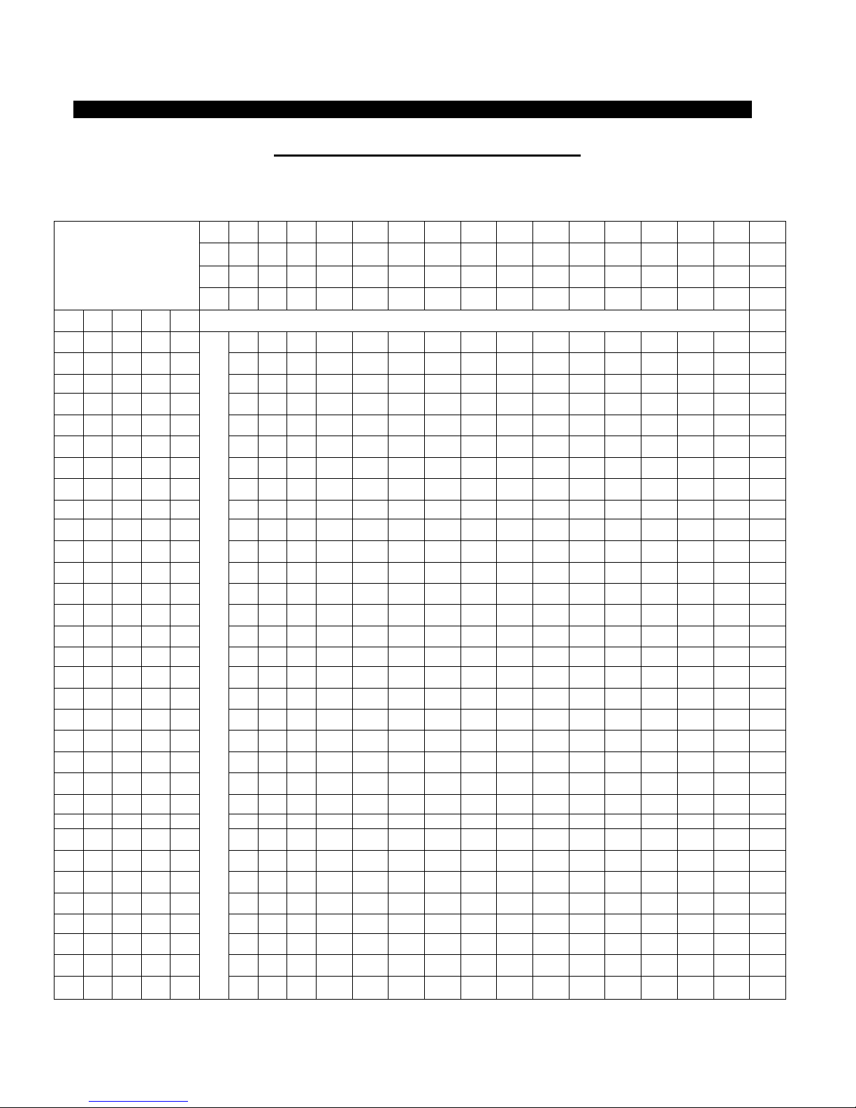
DMX Dipswitch Quick Reference Chart
Dip Switch Position
DMX DIP SWITCH
SET
0=OFF
1=ON
#1 #2 #3 #4 #5
0 0 0 0 0 32 64 96 128 160 192 224 256 288 320 352 384 416 448 480
1 0 0 0 0 1 33 65 97 129 161 193 225 257 289 321 353 385 417 449 481
0 1 0 0 0 2 34 66 98 130 162 194 226 258 290 322 354 386 418 450 482
1 1 0 0 0 3 35 67 99 131 163 195 227 259 291 323 355 387 419 451 483
0 0 1 0 0 4 36 68 100 132 164 196 228 260 292 324 356 388 420 452 484
1 0 1 0 0 5 37 69 101 133 165 197 229 261 293 325 357 389 421 453 485
0 1 1 0 0 6 38 70 102 134 166 198 230 262 294 326 358 390 422 454 486
1 1 1 0 0 7 39 71 103 135 167 199 231 263 295 327 359 391 423 455 487
0 0 0 1 0 8 40 72 104 136 168 200 232 264 296 328 360 392 424 456 488
1 0 0 1 0 9 41 73 105 137 169 201 233 265 297 329 361 393 425 457 489
0 1 0 1 0 10 42 74 106 138 170 202 234 266 298 330 362 394 426 458 490
1 1 0 1 0 11 43 75 107 139 171 203 235 267 299 331 363 395 427 459 491
0 0 1 1 0 12 44 76 108 140 172 204 236 268 300 332 364 396 428 460 492
1 0 1 1 0 13 45 77 109 141 173 205 237 269 301 333 365 397 429 461 493
0 1 1 1 0 14 46 78 110 142 174 206 238 270 302 334 366 398 430 462 494
1 1 1 1 0 15 47 79 111 143 175 207 239 271 303 335 367 399 431 463 495
0 0 0 0 1 16 48 80 112 144 176 208 240 272 304 336 368 400 432 464 496
1 0 0 0 1 17 49 81 113 145 177 209 241 273 305 337 369 401 433 465 497
0 1 0 0 1 18 50 82 114 146 178 210 242 274 306 338 370 402 434 466 498
1 1 0 0 1 19 51 83 115 147 179 211 243 275 307 339 371 403 435 467 499
0 0 1 0 1 20 52 84 116 148 180 212 244 276 308 340 372 404 436 468 500
1 0 1 0 1 21 53 85 117 149 181 213 245 277 309 341 373 405 437 469 501
0 1 1 0 1 22 54 86 118 150 182 214 246 278 310 342 374 406 438 470 502
1 1 1 0 1 23 55 87 119 151 183 215 247 279 311 343 375 407 439 471 503
0 0 0 1 1 24 56 88 120 152 184 216 248 280 312 344 376 408 440 472 504
1 0 0 1 1 25 57 89 121 153 185 217 249 281 313 345 377 409 441 473 505
0 1 0 1 1 26 58 90 122 154 186 218 250 282 314 346 378 410 442 474 506
1 1 0 1 1 27 59 91 123 155 187 219 251 283 315 347 379 411 443 475 507
0 0 1 1 1 28 60 92 124 156 188 220 252 284 316 348 380 412 444 476 508
1 0 1 1 1 29 61 93 125 157 189 221 253 285 317 349 381 413 445 477 509
0 1 1 1 1 30 62 94 126 158 190 222 254 286 318 350 382 414 446 478 510
1 1 1 1 1
Dip Switch Position DMX Address
#9 0 0 0 0 0 0 0 0 1 1 1 1 1 1 1 1
#8 0 0 0 0 1 1 1 1 0 0 0 0 1 1 1 1
#7 0 0 1 1 0 0 1 1 0 0 1 1 0 0 1 1
#6 0 1 0 1 0 1 0 1 0 1 0 1 0 1 0 1
31 63 95 127 159 191 223 255 287 319 351 383 415 447 479 511
Page 12
LEDJ COLOR BURST CHANNEL VALUES
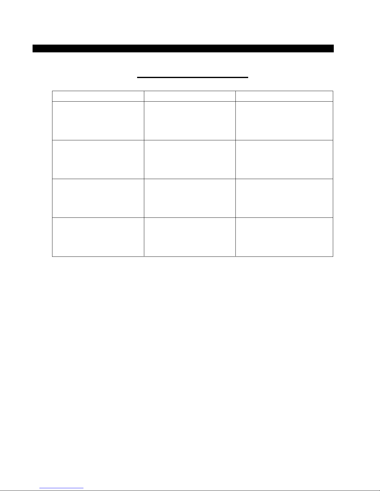
DMX Channel Values
DEFAULT VALUE FUNCTION
1
2
3
000
001<>152
153<>242
000 <> 255
000 <> 255
Shutter/Strobe/Dimmer
Blackout 000
Strobe: speed > 001 - 152
Intensity: 0% > 153 - 242
RED
0 > 100%
GREEN
0 > 100%
4
000 <> 255
BLUE
0 > 100%
Technical Specifications
Weight & Dimensions
• Length…...........................................................125mm
• Width................................................................ 125mm
• Height……………………………………………..145mm
• Weight………………………………………........ 1.1Kgs
Power
• AC input……………………………………..........240V/50hz
• Power Consumption……………………………..10W
Fuse
• Main……………………………………………….20mm Glass 1A Fast Blow
Control & Programming
• Data input………………………………………...Locking 3-pin XLR male socket
• Data output……………………………………….Locking 3-pin XLR female socket
• Protocols………………………………………… DMX-512 UTSITT
• DMX channels…………………………………... 4
 Loading...