

Page 1
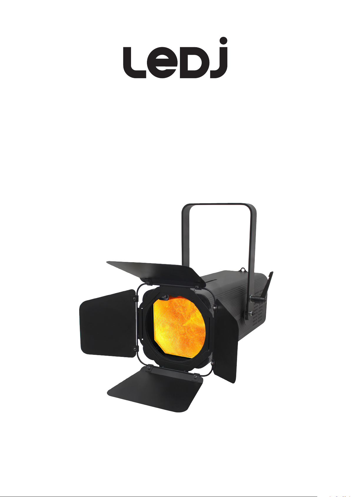
Artisan 2000
RGBWA Fresnel
User Manual
Order code: LEDJ333
Page 2
Safety advice
WARNING
FOR YOUR OWN SAFETY, PLEASE READ THIS USER MANUAL
CAREFULLY BEFORE YOUR INITIAL START-UP!
• Before your initial start-up, please make sure that there is no damage caused during transportation.
• Should there be any damage, consult your dealer and do not use the equipment.
• To maintain the equipment in good working condition and to ensure safe operation, it is necessary
for the user to follow the safety instructions and warning notes written in this manual.
• Please note that damages caused by user modications to this equipment are not subject to warranty.
CAUTION!
KEEP THIS EQUIPMENT
AWAY FROM RAIN,
MOISTURE AND LIQUIDS
CAUTION!
TAKE CARE USING
THIS EQUIPMENT!
HIGH VOLTAGE-RISK
OF ELECTRIC SHOCK!!
IMPORTANT:
The manufacturer will not accept liability for any resulting damages caused by the non-observance
of this manual or any unauthorised modication to the equipment.
• Never let the power cable come into contact with other
cables. Handle the power cable and all mains voltage
connections with particular caution!
• Never remove warning or informative labels from the unit.
• Do not open the equipment and do not modify the unit.
• Do not connect this equipment to a dimmer pack.
• Do not switch the equipment on and off in short intervals,
as this will reduce the system’s life.
• Only use the equipment indoors.
• Do not expose to ammable sources, liquids or gases.
• Always disconnect the power from the mains when
equipment is not in use or before cleaning! Only handle
the power-cable by the plug. Never pull out the plug by
pulling the power-cable.
• Make sure that the available mains supply voltage is
between 100~240V AC, 50/60Hz.
• Make sure that the power cable is never crimped or
damaged. Check the equipment and the power cable
periodically.
• If the equipment is dropped or damaged, disconnect the
mains power supply immediately and have a qualied
engineer inspect the equipment before operating again.
• If the equipment has been exposed to drastic
temperature uctuation (e.g. after transportation),
do not connect power or switch it on immediately.
The arising condensation might damage the equipment.
Leave the equipment switched off until it has reached
room temperature.
• If your product fails to function correctly, stop use
immediately. Pack the unit securely (preferably in the
original packing material), and return it to your Pro Light
dealer for service.
• Only use fuses of same type and rating.
• Repairs, servicing and power connection must only be
carried out by a qualied technician. THIS UNIT CONTAINS
NO USER SERVICEABLE PARTS.
• This lighting xture is for professional use only - it is
not designed for or suitable for household use. The
product must be installed by a qualied technician in
accordance with local territory regulations. The safety of
the installation is the responsibility of the installer. The
xture presents risks of severe injury or death due to re
hazards, electric shock and falls.
• Warning! Risk Group 2 LED product according to
EN 62471. Do not view the light output with optical
instruments or any device that may concentrate the beam.
• WARRANTY: One year from date of purchase.
OPERATING DETERMINATIONS
If this equipment is operated in any other way, than those described in this manual, the product may suffer damage and
the warranty becomes void. Incorrect operation may lead to danger e.g: short-circuit, burns and electric shocks etc.
Do not endanger your own safety and the safety of others!
Incorrect installation or use can cause serious damage to people and/or property.
www.prolight.co.uk Artisan 2000 RGBWA Fresnel User Manual
2
Page 3
Product overview & technical specications
Artisan 2000 RGBWA Fresnel
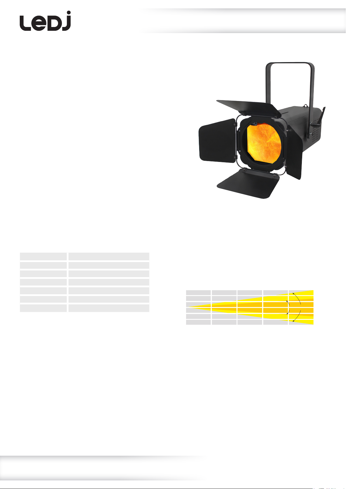
The Artisan 2000 RGBWA Fresnel is ideal for schools, churches and stages and
makes an ideal replacement for tungsten xtures. Control of the unit is facilitated via
a 4 button menu and LCD display, whilst the beam angle can be manually adjusted.
A handy IR remote control is included and an optional W-DMX Compatible Transceiver
can be added into the back panel.
• 1 x 200W ve-colour COB LED (RGBWA)
• Manually adjustable beam angle: 20°- 50°
• 20° - 9,498 Lux @ 2m (full on),
50° - 2,680 Lux @ 2m (full on)
• 2.8kHz refresh rate
• DMX channels: 5/6/7 or 9 selectable
• Artisan Series W-DMX USB compatibility for
wireless master/slave or DMX control
• 0-100% dimming and variable strobe
• 4 dimming curves: Linear, square law,
inverse square law and S-curve
• 4 push button menu with LCD display
• PowerCON input/output
• 5-Pin XLR input/output
• Temperature controlled fan for whisper quiet operation
• Handle on rear panel
• Filter frame and barn doors included
• Supplied with IR remote
20° - Lux
FULL ON
R
G
B
W
A
37992
6672
13684
2724
12136
5148
9498
1668
3421
681
3034
1287
4221
740
1520
302
1348
572
2374
417
855
170
758
321
1519
266
547
108
485
205
Specications Artisan 2000 RGBWA Fresnel
Power consumption 210W
Power supply 100~240V, 50/60Hz
Fuse T3A 250V
Dimensions 365 x 300 x 482mm
Weight 6.1kg
Order code LEDJ333
50° - Lux
FULL ON
R
G
B
W
A
0m 2m 3m 4m 5m1m
10720
2184
4404
916
3936
1720
2680
546
1101
229
984
430
1191
242
489
101
437
191
670
136
275
57.2
246
107
20°
428
87.3
176
36.6
157
68.8
50°
www.prolight.co.uk Artisan 2000 RGBWA Fresnel User Manual
3
Page 4
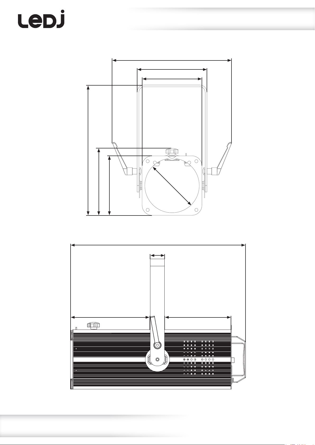
365mm
Technical specications
300mm
195mm
167mm
187mm
167mm
220mm
150mm
482mm
40mm
190mm
www.prolight.co.uk Artisan 2000 RGBWA Fresnel User Manual
4
Page 5

15
04
05
Technical specications
13
12
14
03
06
07
02
11
10
01
08
09
01 - Earth point
02 - LCD display
03 - Function buttons
04 - Colour frame release mechanism
05 - Zoom adjustment
06 - 5-Pin DMX input
07 - 5-Pin DMX output
08 - PowerCON input
09 - PowerCON output
10 - Fuse: T3A 250V
11 - Wireless DMX USB input
12 - Hanging bracket
13 - Hanging bracket adjustable knob
14 - Carry handle
15 - Barn doors
In the box: 1 x xture,
1 x barn doors,
1 x IR remote,
1 x power cable
& 1 x user manual
www.prolight.co.uk Artisan 2000 RGBWA Fresnel User Manual
5
Page 6
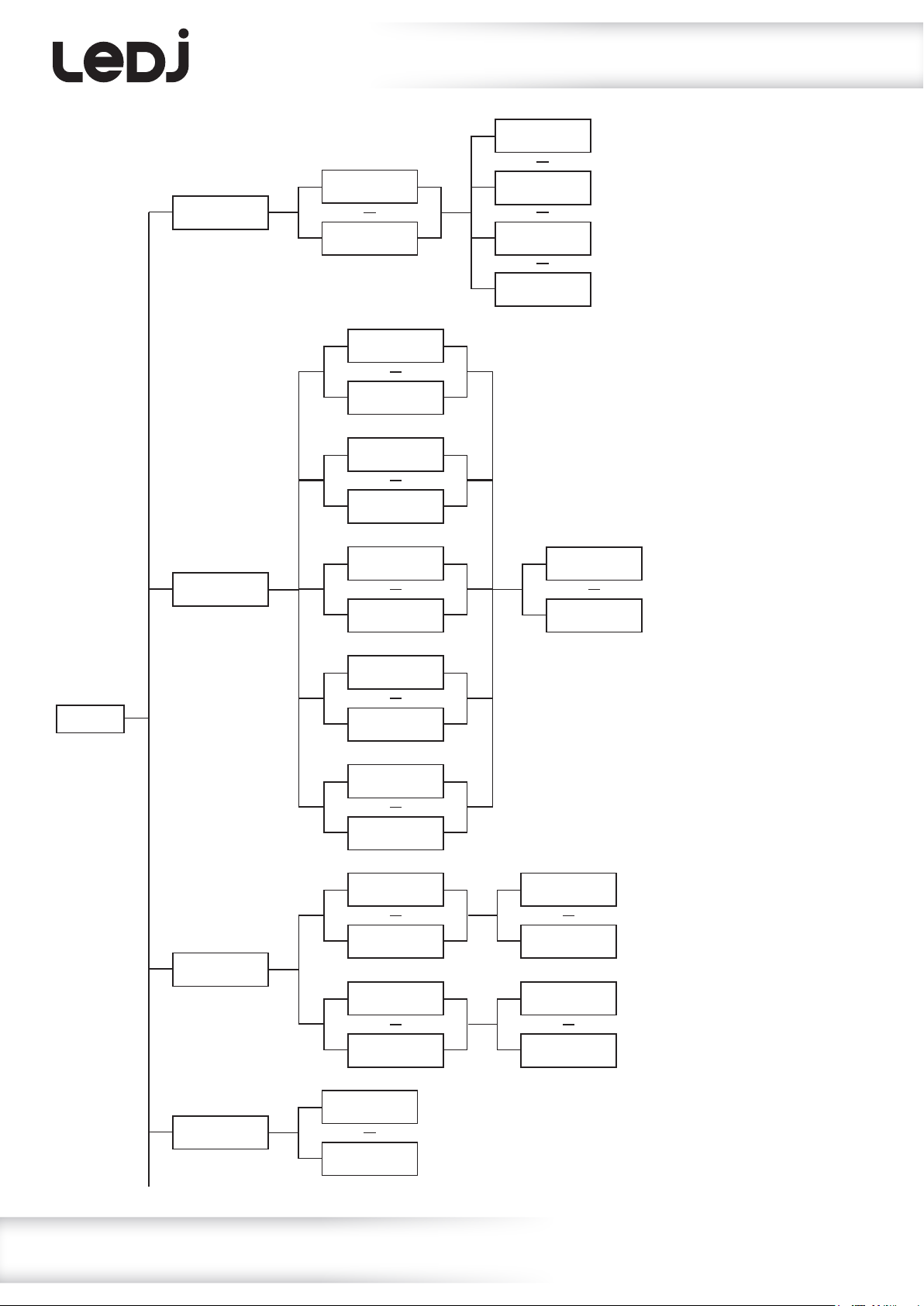
DMX MODE
CHAN: 05
Operating instructions
DMX MODE
ADDR:001
MANUAL
RED: 000
DMX MODE
ADDR:001
DMX MODE
ADDR:512
MANUAL
RED: 000
MANUAL
RED: 255
MANUAL
GREN: 000
MANUAL
GREN: 255
MANUAL
BLUE: 000
MANUAL
BLUE: 255
DMX MODE
CHAN: 06
DMX MODE
CHAN: 07
DMX MODE
CHAN: 09
MANUAL
STROB: 00
MANUAL
STROB: 99
DMX
address
setting
Manual
dimming
mode
MENU
CLR MACS
COLOR: 00
AUTO RUN
FAD+SNAP
MANUAL
WHIT: 000
MANUAL
WHIT: 255
MANUAL
AMBE: 000
MANUAL
AMBE: 255
CLR MACS
COLOR: 00
CLR MACS
COLOR: 25
CLR MACS
COLOR: 26
CLR MACS
COLOR: 44
AUTO RUN
SPEED:00
AUTO RUN
SPEED:99
CLR MACS
STROB:00
CLR MACS
STROB:99
CLR MACS
SPEED:00
CLR MACS
SPEED:99
Auto run mode
Colour/macro mode
www.prolight.co.uk Artisan 2000 RGBWA Fresnel User Manual
6
Page 7
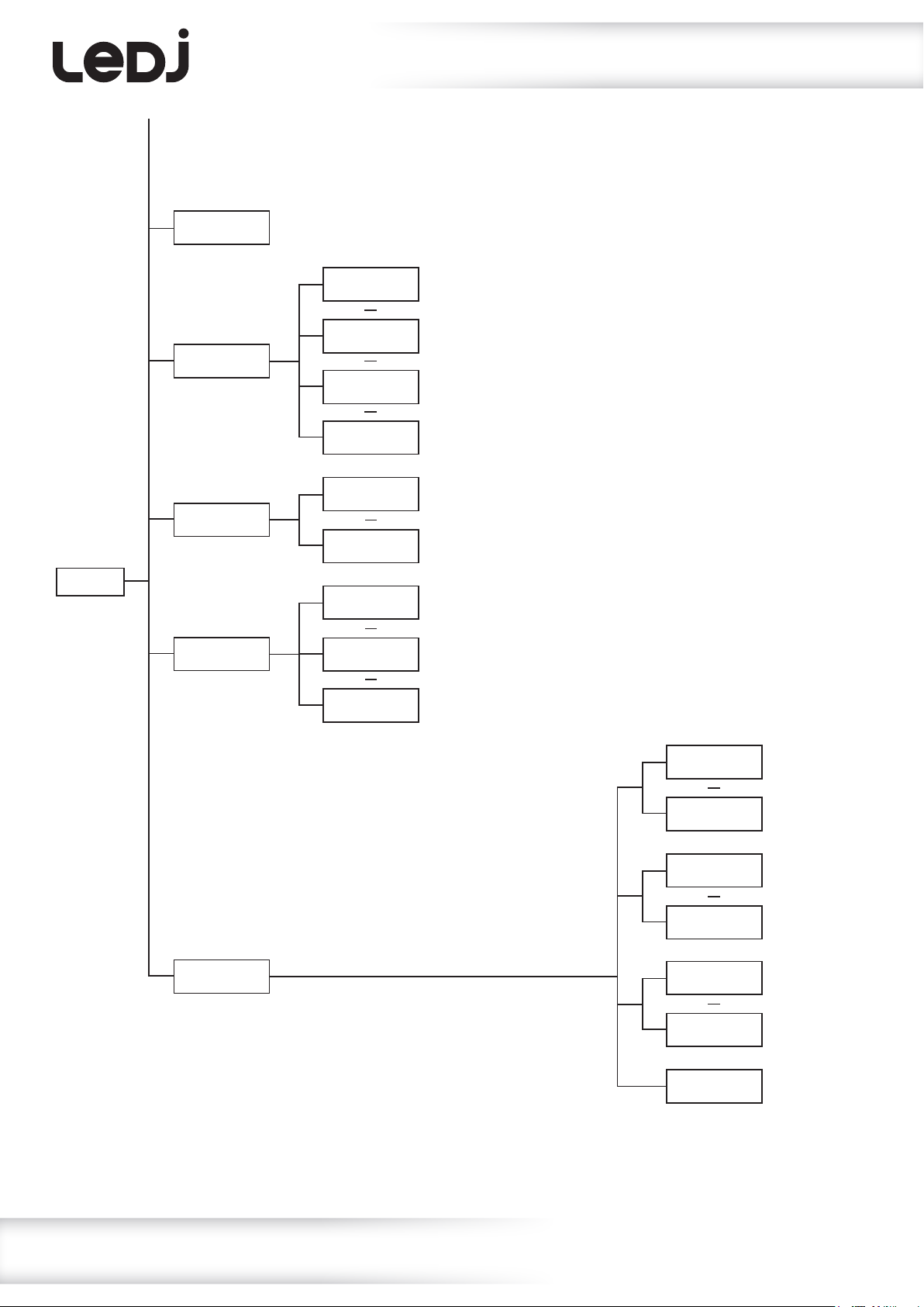
Operating instructions
MENU
SLAVE MODE
DIMCURVE
DIMMODE
DMX FAIL
Slave mode
DIMCURVE
LINEAR
DIMCURVE
SQUARE
DIMCURVE
I-SQUARE
DIMCURVE
S-CURVE
DIMMODE
HALOGEN
DIMMODE
LED
DMX FAIL
BLACKOUT
DMX FAIL
HOLD
Dimming curve setting
Dimming mode setting
DMX fail setting
OTHER
IR: ON
DMX FAIL
STATIC
OTHER
IR : ON
OTHER
IR : OFF
OTHER
BLGT: ON
OTHER
BLGT:OFF
OTHER
WIFI: ON
OTHER
WIFI:OFF
OTHER
SYSRESET
IR setting
Backlight
setting
Wireless
DMX
setting
Reset
factory
settings
www.prolight.co.uk Artisan 2000 RGBWA Fresnel User Manual
7
Page 8
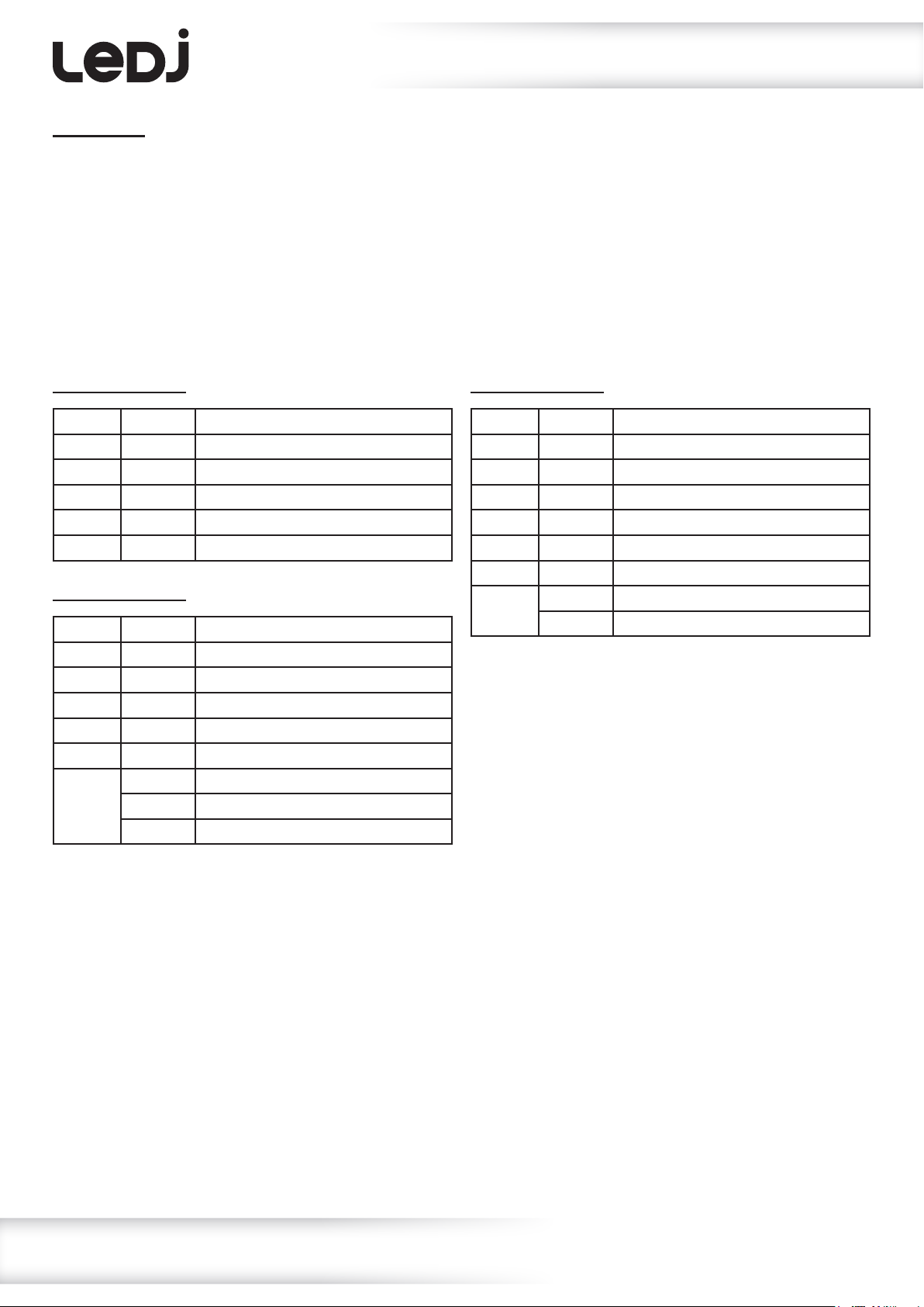
Operating instructions
DMX mode:
Operating in a DMX control mode environment gives the user the greatest exibility when it comes
to customising or creating a show. In this mode you will be able to control each individual trait of the
xture and each xture independently.
To access the DMX address mode, press the “MENU” button to show “DMX MODE ADDR” on the LCD
display. Now use the “UP” and “DOWN” buttons to set the required DMX address. Press the “ENTER”
button to show “DMX MODE CHAN” on the LCD display and use the “UP” and “DOWN” buttons to
select the required the DMX channel (5/6/7 or 9 selectable). Press the “ENTER” button to conrm
the setting. To exit out of any of the above options, press the “MENU” button.
5 channel mode:
Channel Value Function
1 000-255 Red dimmer (0-100%)
2 000-255 Green dimmer (0-100%)
3 000-255 Blue dimmer (0-100%)
4 000-255 White dimmer (0-100%)
5 000-255 Amber dimmer (0-100%)
6 channel mode:
Channel Value Function
1 000-255 Red dimmer (0-100%)
2 000-255 Green dimmer (0-100%)
3 000-255 Blue dimmer (0-100%)
4 000-255 White dimmer (0-100%)
5 000-255 Amber dimmer (0-100%)
6 000-189 Master dimmer (0-100%)
190-250 Strobe (slow-fast)
251-255 Full on
7 channel mode:
Channel Value Function
1 000-255 Red dimmer (0-100%)
2 000-255 Green dimmer (0-100%)
3 000-255 Blue dimmer (0-100%)
4 000-255 White dimmer (0-100%)
5 000-255 Amber dimmer (0-100%)
6 000-255 Master dimmer (0-100%)
7 000-004 No function
005-255 Strobe (slow-fast)
www.prolight.co.uk Artisan 2000 RGBWA Fresnel User Manual
8
Page 9
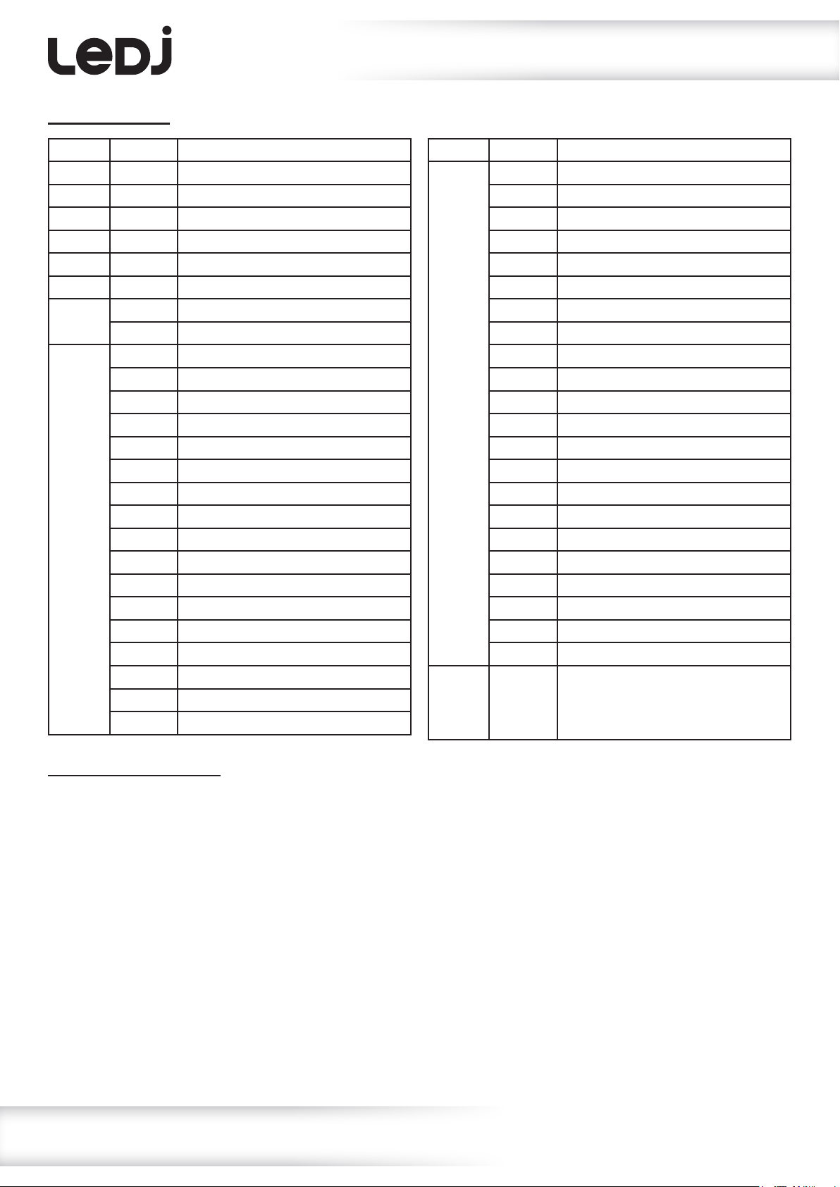
9 channel mode:
Operating instructions
Channel Value Function
1 000-255 Red dimmer (0-100%)
2 000-255 Green dimmer (0-100%)
3 000-255 Blue dimmer (0-100%)
4 000-255 White dimmer (0-100%)
5 000-255 Amber dimmer (0-100%)
6 000-255 Master dimmer (0-100%)
7 000-004 No function
005-255 Strobe (slow-fast)
8 000-005 Blackout
006-010 Red
011-015 Orange
016-020 Yellow
021-025 Green
026-030 Cyan
031-035 Blue
036-040 Pink
041-045 Magenta
046-050 Cool white
051-055 Warm white
056-060 Full on
061-065 Light pink
066-070 Light apricot
071-075 Light ochre
076-080 Grey pearl
081-085 Green pearl
Channel Value Function
8 (cont.) 086-090 Green veronese
091-095 Blue lagoon
096-100 Sky blue
101-105 Light blue
106-110 Cerulean blue
111-115 Fluo
116-120 Candy
121-155 Amber
156-160 Macro 1
161-165 Macro 2
166-170 Macro 3
171-175 Macro 4
176-180 Macro 5
181-185 Macro 6
186-190 Macro 7
191-195 Macro 8
196-200 Macro 9
201-205 Macro 10
206-210 Macro 11
211-215 Macro 12
216-220 Macro 13
221-255 Macro 14
9 000-255 No function
(when CH8 is between 000-155)
Speed (slow-fast)
(when CH8 is between 156-255)
Manual dimming mode:
To access the manual dimming mode press the “MENU” button until the display shows “MANUAL RED”
on the LCD display. Use the “UP” and “DOWN” buttons to select the required brightness of red from
“000” ~ “255”. Press the “ENTER” button and repeat for “GREN” (green), “BLUE” (blue), “WHIT” (white)
and “AMBE” (amber). Now press the “ENTER” button and then use the “UP” and “DOWN” buttons to
select the strobe speed from “00” ~ “99”. Press the “ENTER” button to conrm the setting.
Value: 000 - 255 (000 = LED off, 255 = high brightness)
Value: 00 - 99 (00 = no strobe, 99 = fast strobe speed)
To exit out of any of the above options, press the “MENU” button.
www.prolight.co.uk Artisan 2000 RGBWA Fresnel User Manual
9
Page 10

Operating instructions
Colour/macro mode:
To access the colour mode, press “MENU” until the display shows “CLR MACS” on the LCD
display. Use the “UP” and “DOWN” buttons to select the required colour/macro speed from
“COLOR: 00” ~ “COLOR: 25”/“MACRO: 26” ~ “MACRO: 44”.
When a colour has been selected, press the “ENTER” button and then use the “UP” and “DOWN”
buttons to select the strobe speed from “00” ~ “99”. Press the “ENTER” button to conrm the setting.
When a macro has been selected, press the “ENTER” button and then use the “UP” and “DOWN”
buttons to select the speed from “00” ~ “99”. Press the “ENTER” button to conrm the setting.
Value: 00 - 99 (00 = no strobe, 99 = fast strobe speed)
Value: 00 - 99 (00 = slow speed, 99 = fast speed)
To exit out of any of the above options, press the “MENU” button.
Auto run mode:
To access the auto run mode, press “MENU” until the display shows “AUTO RUN” on the LCD
display. Use the “UP” and “DOWN” buttons to select the required speed from “00” ~ “99”.
Press the “ENTER” button to conrm the setting.
Value: 00 - 99 (00 = slow speed, 99 = fast speed)
To exit out of any of the above options, press the “MENU” button.
Master/slave mode:
To set the master unit, press the “MENU” button on the master unit to select either the manual mode,
colour/macro mode or auto run mode.
To set the other units in slave mode, press the “MENU” button on the slave unit to show “SLAVE MODE”.
Press the “ENTER” button to conrm the setting.
To exit out of any of the above options, press the “MENU” button.
Please ensure that all slave units are set to the same DMX channel mode as the master unit.
Dimming curves:
To access the xtures dimming curves, press the “MENU” button to show “DIMCURVE” on the LCD
display. Now use the “UP” and “DOWN” buttons on the rear of the unit to select between “LINEAR”,
“SQUARE”, “I-SQUARE” and “S-CURVE”. Press the “ENTER” button to conrm the setting.
To exit out of any of the above options, press the “MENU” button.
Dimming mode:
To access the xtures dimming mode, press the “MENU” button to show “DIMMODE” on the LCD display.
Now use the “UP” and “DOWN” buttons on the rear of the unit to select between “HALOGEN” and
“LED”. Press the “ENTER” button to conrm the setting.
To exit out of any of the above options, press the “MENU” button.
www.prolight.co.uk Artisan 2000 RGBWA Fresnel User Manual
10
Page 11

Operating instructions
DMX fail setting:
To access the xtures DMX fail setting, press the “MENU” button to show “DMX FAIL” on the LCD
display. Now use the “UP” and “DOWN” buttons on the rear of the unit to select between “BLACKOUT”,
(blacks out the xture when signal is lost) “HOLD” (holds last DMX command) and
“STATIC” (manual mode). Press the “ENTER” button to conrm the setting.
To exit out of any of the above options, press the “MENU” button.
IR setting:
To access the units IR setting, press “MENU” to show “OTHER BLGT” on the LCD display. Press the “EN-
TER” button to show “OTHER IR” on the LCD display and use the “UP” and “DOWN”
buttons to select the between “ON” (IR receiver on) and “OFF” (IR receiver off).
Press the “ENTER” button to conrm the setting.
To exit out of any of the above options, press the “MENU” button.
Backlight setting:
To access the units backlight setting, press “MENU” to show “OTHER BLGT” on the LCD display. Use the
“UP” and “DOWN” buttons to select the between “ON” (backlight on) and “OFF” (backlight goes off after
20 seconds). Press the “ENTER” button to conrm the setting.
To exit out of any of the above options, press the “MENU” button.
Wireless DMX setting:
To access the units Wireless DMX setting, press “MENU” to show “OTHER WIFI” on the LCD display.
Use the “UP” and “DOWN” buttons to select the between “ON” and “OFF.
Press the “ENTER” button to conrm the setting.
To exit out of any of the above options, press the “MENU” button.
Reset factory settings:
To reset the unit back to its factory settings, press “MENU” to show “OTHER BLGT” on the LCD display.
Press the “ENTER” button twice to show “SYSRESET” on the LCD display. Press both the “UP” and
“DOWN” buttons together and the unit will reset to factory settings.
Press the “ENTER” button to conrm the setting.
To exit out of any of the above options, press the “MENU” button.
www.prolight.co.uk Artisan 2000 RGBWA Fresnel User Manual
11
Page 12
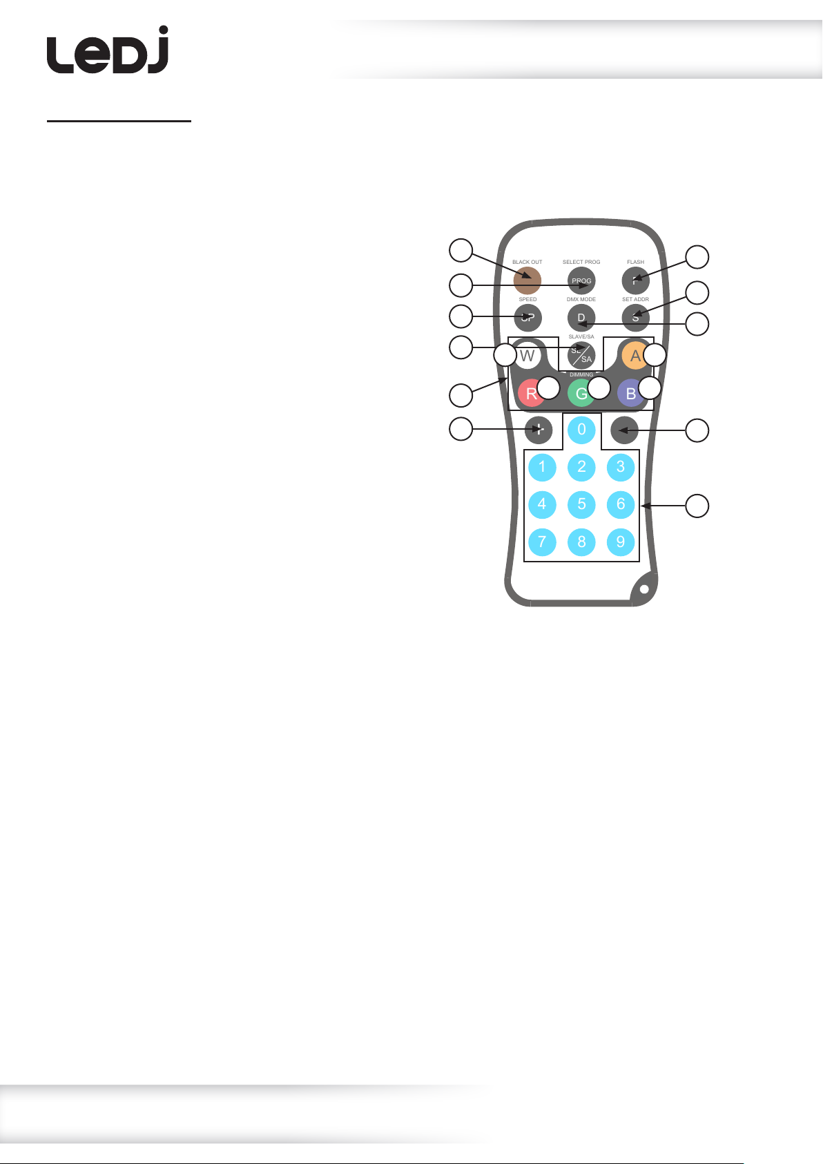
BLACK OUT SELECT PROG FLASH
PROG
F
SET ADDR
S
DMX MODE
D
SPEED
SP
SLAVE/SA
SL
SA
W
R G B
A
0
31 2
4 5 6
8 9
+
7
DIMMING
IR remote functions:
01 - Sets the unit into blackout off/on (LED on/off)
02 - Activates the static colours/macros, use the ‘PROG’
button to cycle through static colour and macros modes.
Static colour - use the ‘+’ and ‘–’ buttons to select the
required colour. Use the ‘F’ button followed by the ‘+’ and
‘–’ buttons to set the ash speed
Macros - use the ‘SP’ button followed by the ‘+’ and ‘–’
buttons to adjust the selected macro speed
03 - Activates the strobe, use the ‘+’ and ‘–’ buttons
to adjust the strobe speed
04 - Activates the auto run/macro speed.
Press this button followed by the ‘+’ and ‘–’ buttons to
adjust the program speed
05 - Activates the DMX mode. Press once and use the ‘+’
and ‘–’ buttons to adjust the DMX DMX channel mode.
The LEDs will ash to conrm the channel mode the
xture is in.
Red - 5 channel
Green - 6 channel
Blue - 7 channel
White - 9 channel
06 - Sets the DMX address, press once followed by three
numeric buttons to set the DMX address required
07 - Activates the auto run mode. Press the ‘SP’ button
followed by the ‘+’ and ‘–’ buttons to adjust the speed.
Press again to activate slave mode.
08 - Activates the manual dimming mode, select one of the
colours below and use the ‘+’ and ‘–’ buttons to select
the brightness between 000-255. Repeat for all 4 other
colours.
A - Red B - Green C - Blue D - White E - Amber
09 - Adjusts the colour macros, strobe speed, auto run
speed, macro speed mode, DMX address, DMX channel
mode and manual dimming modes
10 - Sets the DMX address
01
02
04
07
08
09
Operating instructions
03
06
05
ED
A B C
09
10
www.prolight.co.uk Artisan 2000 RGBWA Fresnel User Manual
12
Page 13
Operating instructions
Wireless operation:
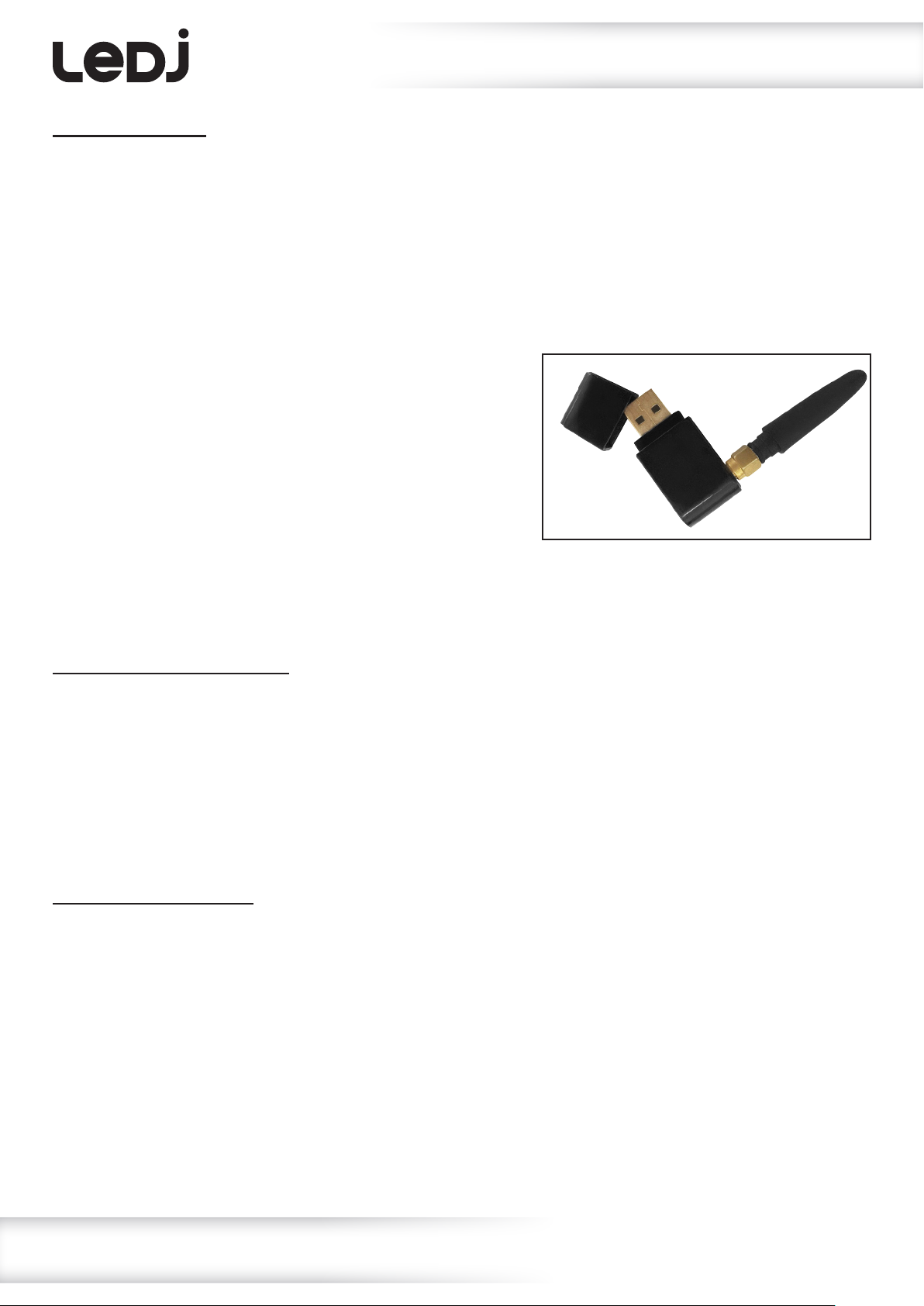
To operate the xture wirelessly you will need to plug in the Artisan Series W-DMX Compatible
Transceiver (sold separately) into the USB port on the rear of the xture. W-DMX should also be set
to “ON” in the xtures settings (full instructions can be found on page 9).
If using it in wireless DMX mode a compatible wireless DMX Transmitter (e.g. Wireless Solutions Sweden
W-DMX Micro F-1 Lite G5 Transceiver) will need to be connected.
The Artisan Series W-DMX Compatible Transceiver features 2 operating protocols as listed below.
The LED on the side of the dongle will illuminate a different colour for each operating protocol.
W-DMX G3 Transmit Protocol - Blue (when transmitting)
W-DMX Receive Protocol - Green (when receiving)
To set the dongle in one of these modes plug the
Artisan Series W-DMX Compatible Transceiver into
the USB port on the rear of the xture. Hold down
the button on the dongle whilst powering on the unit.
The LED will illuminate white for a brief moment and
then change colour. You can then press the button which
will scroll through the operating protocols. Once you have selected the chosen protocol, press and hold
the button on the dongle for 3 seconds. The LED will illuminate white, then turn blue (transmit mode) or
stay white (receive mode). The unit is now set in your chosen protocol.
W-DMX G3 Transmit Protocol:
Once in this protocol the LED will illuminate blue. This indicates the xture is ready to pair with the
receiver(s). Once all the receiver(s) have been set up press the button on the dongle once and the LED
will ash blue quickly, this indicates it is attempting to pair with the receivers. Once pairing is complete
the LED will illuminate static blue to indicate the xture is transmitting signal.
To disconnect the transmitting xture from all receiving xtures within range when connected, hold the
button on the transmitting xtures dongle down for 3 seconds until the LED illuminates red.
This indicates the wireless memory has been cleared.
W-DMX Receive Protocol:
Once in this protocol the LED will illuminate white. This indicates a connection has not yet been
established with the transmitter. Once the transmitter has been set up press the button on the
transmitter xtures dongle once or press the pair button on your wireless transceiver. The LED on the
receiving units will ash green quickly, this indicates it is attempting to pair with the transmitter.
Once pairing is complete the LED will illuminate static green to indicate the xture is receiving signal.
To disconnect the transmitting xture from all receiving xtures within range when connected, hold the
button on the transmitting xtures dongle down for 3 seconds until the LED illuminates white.
This indicates the wireless memory has been cleared.
If the indicator on the receiving units ashes red quickly this indicates that the signal from the
transmitting xture has been lost.
www.prolight.co.uk Artisan 2000 RGBWA Fresnel User Manual
13
Page 14
DMX setup
Setting the DMX address:
The DMX mode enables the use of a universal DMX controller. Each xture requires a “start address”
from 1- 512. A xture requiring one or more channels for control begins to read the data on the channel
indicated by the start address. For example, a xture that occupies or uses 7 channels of DMX and was
addressed to start on DMX channel 100, would read data from channels: 100, 101, 102, 103, 104,
105 and 106. Choose a start address so that the channels used do not overlap. E.g. the next unit in
the chain starts at 107.
DMX 512:
DMX (Digital Multiplex) is a universal protocol used as a form of communication between intelligent
xtures and controllers. A DMX controller sends DMX data instructions form the controller to the xture.
DMX data is sent as serial data that travels from xture to xture via the DATA “IN” and DATA “OUT”
XLR terminals located on all DMX xtures (most controllers only have a data “out” terminal).
DMX linking:
DMX is a language allowing all makes and models of different manufactures to be linked together
and operate from a single controller, as long as all xtures and the controller are DMX compliant.
To ensure proper DMX data transmission, when using several DMX xtures try to use the shortest
cable path possible. The order in which xtures are connected in a DMX line does not inuence the
DMX addressing. For example; a xture assigned to a DMX address of 1 may be placed anywhere in
a DMX line, at the beginning, at the end, or anywhere in the middle. When a xture is assigned a
DMX address of 1, the DMX controller knows to send DATA assigned to address 1 to that unit,
no matter where it is located in the DMX chain.
DATA cable (DMX cable) requirements (for DMX operation):
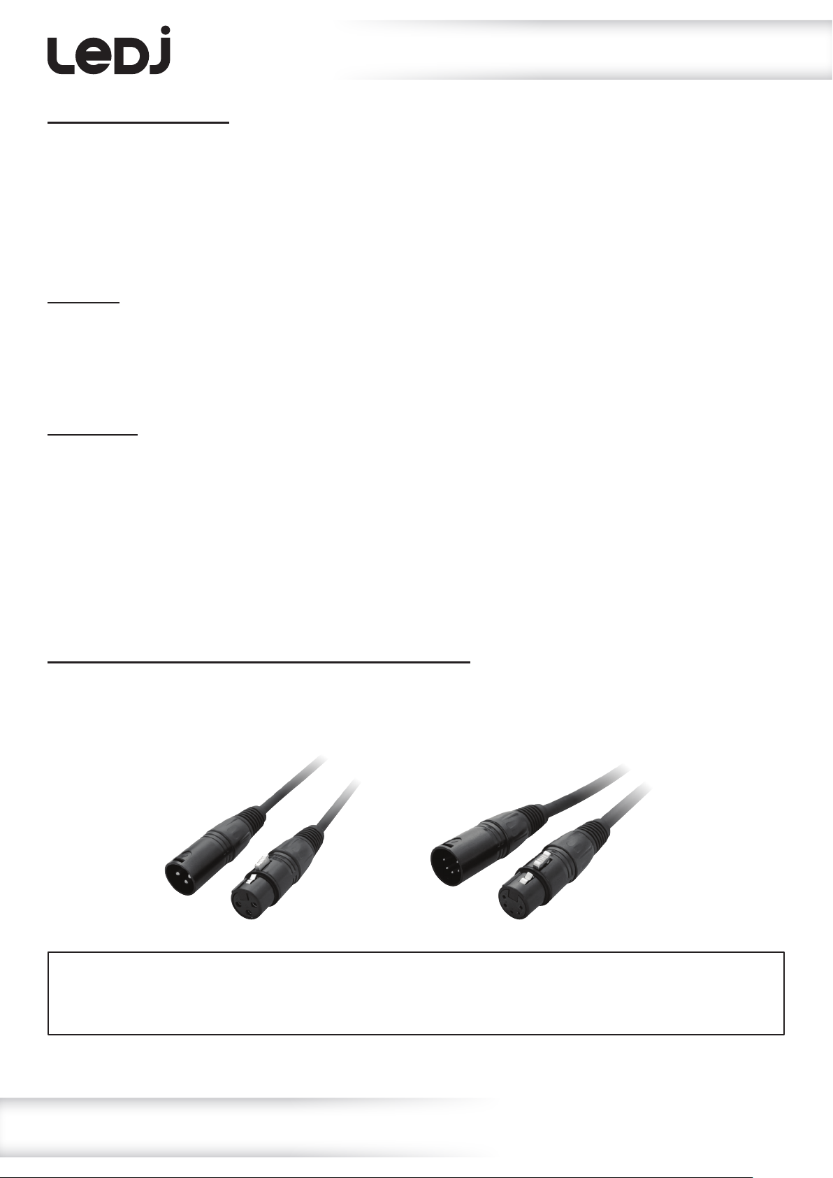
This xture can be controlled via DMX-512 protocol. The DMX address is set on the back of the unit.
Your unit requires either a standard 3-pin or 5-pin XLR connector for data input/output,
see images below.
Further DMX cables can be purchased from all good sound and lighting suppliers or Prolight Concepts dealers.
Please quote:
Also remember that DMX cable must be daisy chained and cannot be split.
CABL10 – 2m CABL11 – 5m CABL12 – 10m3-Pin:
CABL185 – 2m CABL187 – 5m CABL188 – 10m5-Pin:
www.prolight.co.uk Artisan 2000 RGBWA Fresnel User Manual
14
Page 15
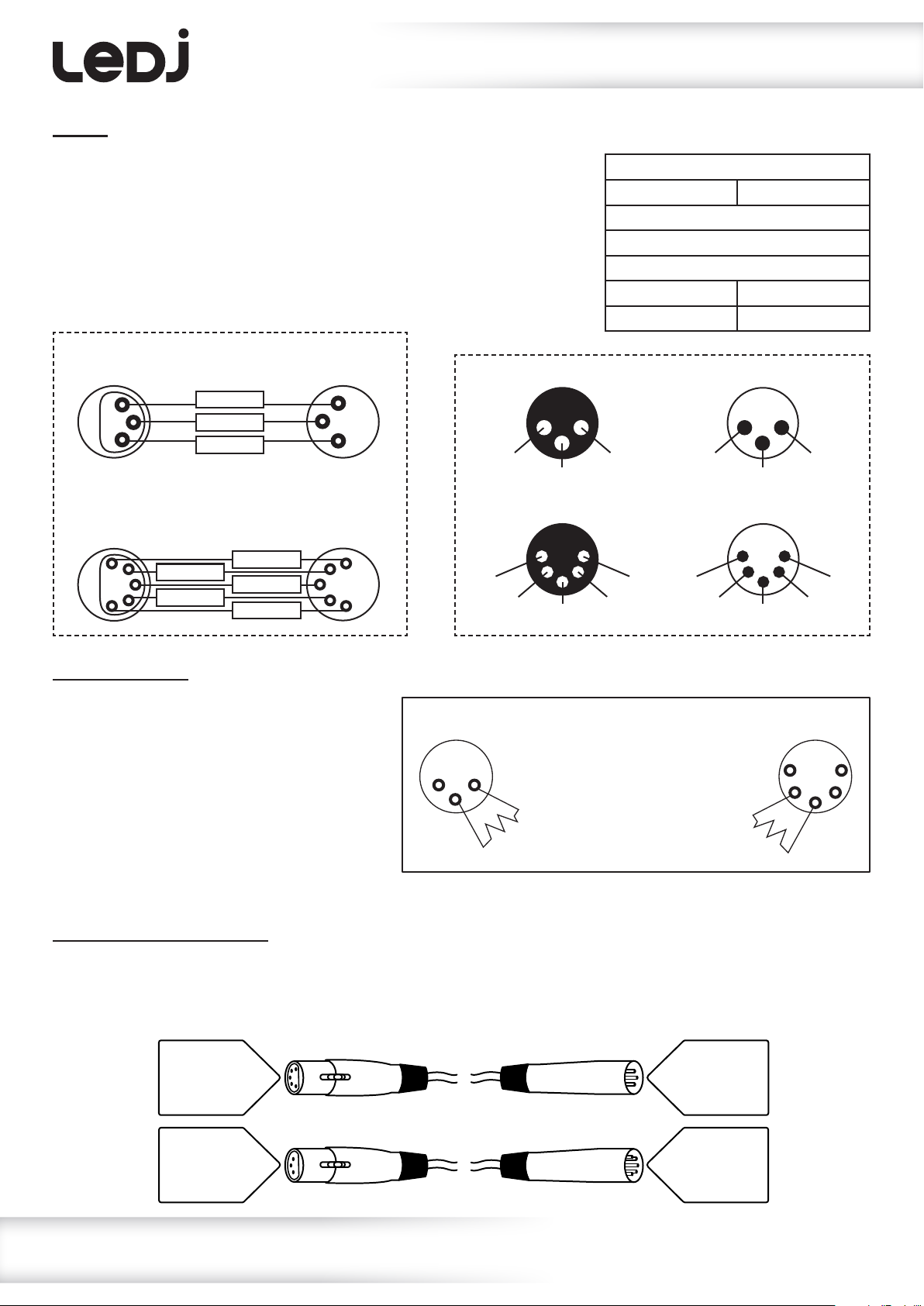
Notice:
DMX setup
Be sure to follow the diagrams below when making your own cables.
Do not connect the cables shield conductor to the ground lug or
allow the shield conductor to come in contact with the XLRs
outer casing. Grounding the shield could cause a short circuit
and erratic behaviour.
DMX 512
3-Pin XLR output
1
3
2
DMX 512
5-Pin XLR output
1
2
3
4
5
GROUND
DMX –
N/C
DMX +
DMX –
GROUND
DMX +
N/C
DMX 512
3-Pin XLR input
1
3
2
DMX 512
5-Pin XLR input
1
2
3
4
5
3-Pin XLR male 3-Pin XLR female
1 ground
3 hot
5-Pin XLR male 5-Pin XLR female
1 ground 5 N/C
2 cold
3 hot
2 cold
4 N/C
Pin Conguration
3-Pin 5-Pin
Pin 1 - Ground
Pin 2 - Negative
Pin 3 - Positive
– Pin 4 - N/C
– Pin 5 - N/C
2 cold
5 N/C 1 ground
4 N/C
3 hot
3 hot
1 ground
2 cold
Line termination:
When longer runs of cable are used,
you may need to use a terminator on
the last unit to avoid erratic behaviour.
Using a cable terminator will decrease
the possibilities of erratic behaviour.
(3-pin - Order ref: CABL90,
3-Pin
1 2
3
Termination reduces signal
transmission problems and
interference. It is always
advisable to connect a DMX
terminal, (resistance 120
Ohm 1/4W) between pin 2
(DMX-) and pin 3 (DMX+) of
the last xture.
5-Pin
1
2 4
3
5
5-pin - Order ref: CABL89)
5-pin XLR DMX connectors:
Some manufactures use 5-pin XLR connectors for data transmission in place of 3-pin. 5-pin XLR xtures
may be implemented in a 3-pin XLR DMX line. When inserting standard 5-pin XLR connectors in to a
3-pin line a cable adaptor must be used. The diagram below details the correct cable conversion.
5-pin XLR (female)
Pin 1: GND (screen)
Pin 2: Signal (-)
Pin 3: Signal (+)
Pin 4: N/C
Pin 5: N/C
3-pin XLR (male)
Pin 1: GND (screen)
Pin 2: Signal (-)
Pin 3: Signal (+)
3-pin XLR (female)
Pin 1: GND (screen)
Pin 2: Signal (-)
Pin 3: Signal (+)
5-pin XLR (male)
Pin 1: GND (screen)
Pin 2: Signal (-)
Pin 3: Signal (+)
Pin 4: N/C
Pin 5: N/C
www.prolight.co.uk Artisan 2000 RGBWA Fresnel User Manual
15
Page 16
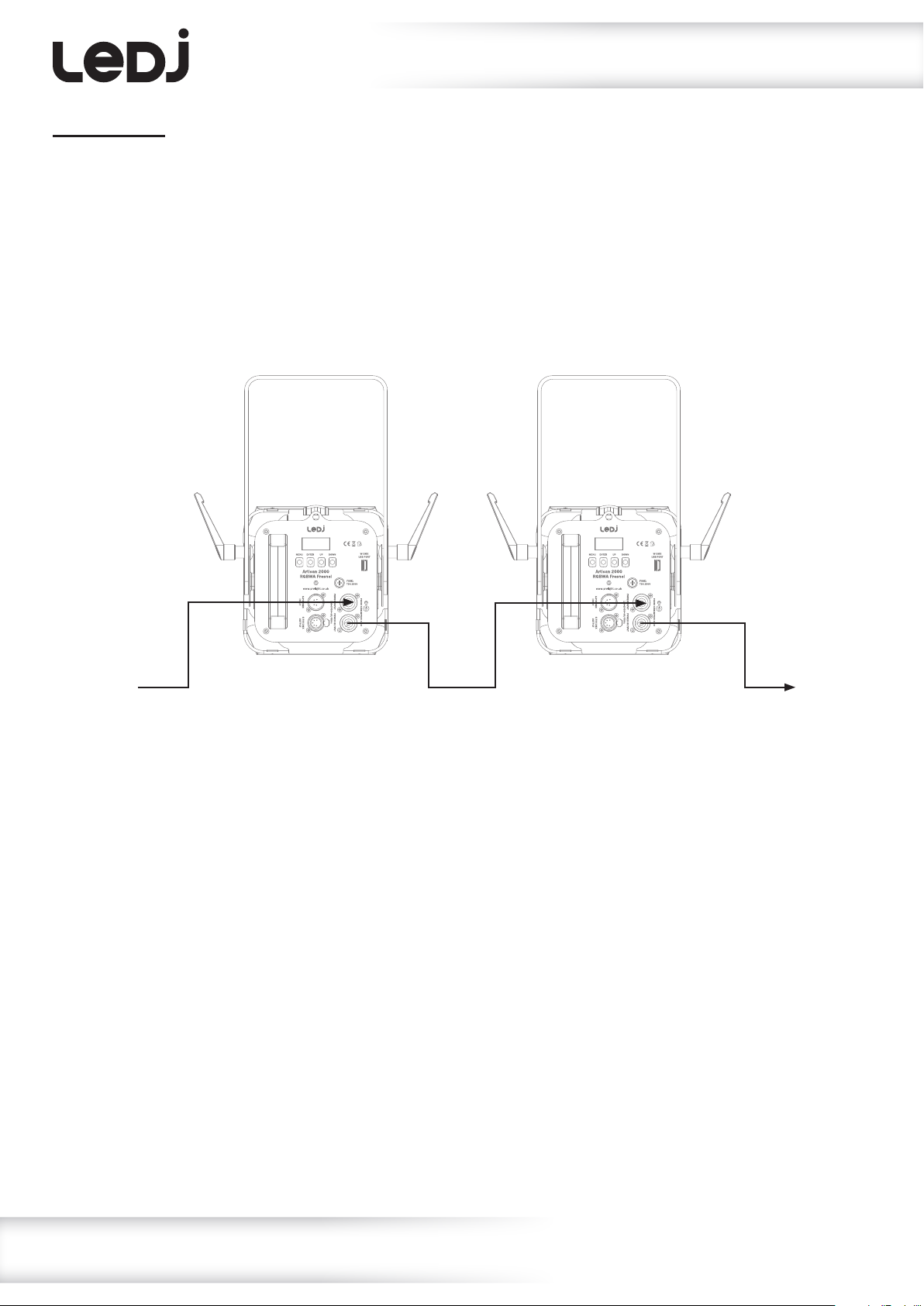
Multiple xture power linking
Power linking:
This xture provides power linking via the power output on the rear allowing multiple units to be
connected together. The maximum number of xtures that can be connected is 10 xtures @ 240V
or 5 xtures @ 120V (including the rst xture). After the maximum number of xtures are
connected a new power run will need to be started.
Please note: Caution should be used when power linking other xtures to the Artisan 2000 Dual White
Fresnel as the power consumption of other xtures will vary. Fixtures tted with lamps often require 2/3
times more current on startup, these may require their own power source.
www.prolight.co.uk Artisan 2000 RGBWA Fresnel User Manual
16
Page 17
WEEE notice
Correct Disposal of this Product
(Waste Electrical & Electronic Equipment)
(Applicable in the European Union and other European countries
with separate collection systems)
This marking shown on the product or its literature, indicates that it should not be disposed
with other household wastes at the end of its working life. To prevent possible harm to the
environment or human health from uncontrolled waste disposal, please separate this from other
types of wastes and recycle it responsibly to promote the sustainable reuse of material resources.
Household users should contact either the retailer where they purchased this product, or their
local government ofce, for details of where and how they can take this item for environmentally
safe recycling.
Business users should contact their supplier and check the terms and conditions of the
purchase contract. This product should not be mixed with other commercial wastes for disposal.
www.prolight.co.uk Artisan 2000 RGBWA Fresnel User Manual
17
Page 18

www.prolight.co.uk Artisan 2000 RGBWA Fresnel User Manual
18
Page 19

www.prolight.co.uk Artisan 2000 RGBWA Fresnel User Manual
19
Page 20

www.prolight.co.uk Artisan 2000 RGBWA Fresnel User Manual
20
 Loading...