

Page 1
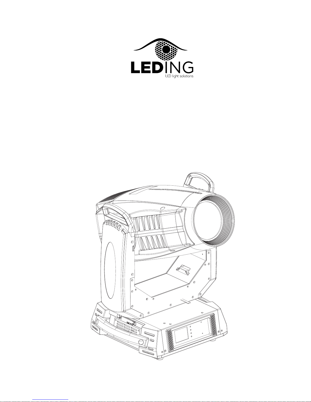
Razer 440
USER MANUAL
Page 2

Table of content
1.Open-Package guidelines............................................................1
1.1Package................................................................................1
2.Safety instructions......................................................................1
3.Operating determination.............................................................3
4.Rigging the fixture.......................................................................4
4.1 Mounting.................................................................................4
5.
6.
7.
7.1
7.2
7.3
8.DMX protocol.............................................................................12
9.Maintance and cleaning.............................................................15
10.Electric equipment specification...............................................15
10.1 Electrical paramters............................................................15
10.2
10.3
10.5 light table .............................................16
10.7 ....................................................................18
11.Electronic drawing...................................................................19
4.2Installing the Clamps................................................................4
4.3 Power supply connection and cut off........................................5
4.4 POWER Connection.................................................................6
4.5 DMX-512 connection/connection between fixtures.................6
.......................................................15
Channel Characteristics.......................................................15
10.4 Menu Function.....................................................................15
..............................
10.6 Gobo wheel.........................................................................17
Color wheel.....
Description of the device..............................................................7
Dimension....................................................................................8
Display control.............................................................................9
Navigation in the Menu............................................................9
Display OPeration....................................................................9
Menu Maps .............................................................................11
Weight and dimensions
Page 3
2.Safety instructions
1.Open-Package guidelines
1.1Package
Unpac king the fi xture
1.Ope n the fligh t case cove r
2.Wit h one perso n on each sid e, lift the f ixture out of the flight case.
3.Unl ock pan and t ilt befor e operating fixture.
Packi ng the fixt ure
1.Dis connect t he fixtur e from powe r and allow it to cool.
2.loc k arms and h as figu re. (
3.Pla ce the fix tu re in the bot tom of the fl ight case , and cover the case without forcing.
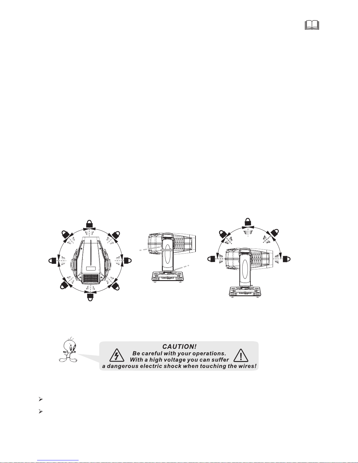
- Fig.1
ead - Fig.1 PAN Mec hanism Lock and Release (e very 45°)
- Fig.1 -1)(Tilt Me chanism L ock and Rel ease (eve ry 45°) - Fig .1-2)
Congratula tions on choosi ng our products! Please carefully read this instru ction manual in its entirety and
well for using reference . Th is manual containe d about the in stallation and the relative using inform
ducts.P lese refere this manual's relative when using this eq uip ment.
This equipment is made of new style,hi gh intensity plast ic.It fully sho ws the modem time s light charac
teristi c with beauty str uture. And it is made accor d to CE standard. Fully agree with the internatio n
512 ag reement.
keep it
ation of this pro instruc tion
teristic wi th
standar d of DMX
1.Sig nal cable -1PC 2.Safty cable-1PC
3.Use r Manval- 1PC 4.Omega holder-2PCS
5.Pow er cable- 1PC 5.Service card-1PC
When receive t h e p r o d u c t , p l e a s e be careful t o t a k e and put,check i f the product h a s d a m a g e or not b e -
1
cause o f transpo rtation , and check the fol lowing pa rts:
This device has bee n shippe d with our premises in absolutely perfect condition.In or der to maintain this condition and toensure a safe operation,it is absolutely necessary for the use r to follow the safety instructions
and warning notes writ ten i n this manual.
Important:
The manufacturer will not acc ept l iab ili ty for any resulting damages caused by the no nob ser van ce of this
manual or any un aut hor ize d mod ifi cat ion to the device.
Please co nsider that damages caused by manual modifications to the devi ce ar e not subject to warranty.
Every p erson inv olvd with i nstallation and mainte nance of th is device t o:
-Be qua lilfied
-Foll ow the inst ruction s of this man ual.
Fig.1- 2
Level vertical transportation lock Fig.1
PAN Me ch an is m Lo ck
PAN Me ch an is m Lo ck
Fig.1-1
4
5
°
4
5
°
4
5°
4
5
°
45°
4
5
°
45°
4
5°
A
rm
l
o
c
k
A
rm
l
o
c
k
LO CK ED UN LO CK ED
H
ea
d
l
oc
k
4
5
°
4
5°
4
5
°
4
5
°
Page 4
2
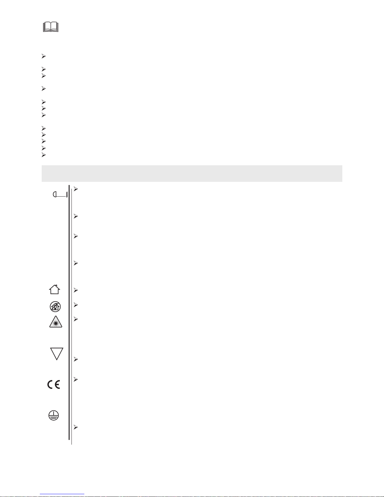
Never l et the powe r-cord co me into con tact with other cables! Handle the po wer cord an d all conne ctions
with pa rticula r caution !
Make su re that the a vailabl e voltage i s not higher than stated on th e rearpan el.
A lways pl ug in the pow er plug least. Make suer that the power -switch i s set to off -positi on before y ou con
ectio ns with the mains wit h particu lar caution!
Make su re that the p ower-co rd is never c rimped or damaged by sharp e dges.Ch eck the dec ice and the p ower- cord from t ime to time .
Always d isconne ct from the m ains, whe n the device is not in use or befo re cleani ng it.
Only han dle the pow er-cord b y the plug, Never pul l out the plug by tugging the po wercord .
This device fall s under protection class I.Theref ore it is ess ential to c onnect th e yellow/ green con ductor
to eart h.
The electric connect ion,rep airs and se rvicing m ust be carr ied out by a qu alified e mployee.
Do no t connect t his devic e to a dimmer p ack.
Do no t switch th e fixture o n and off in s hort inte rvals as th is would reduce the lamp’s life.
Do not to uch the dev ice’s housin g bare hand s during it s operati on(hous ing becom es hot)!
For rep lacemen t use lamps a nd fuses of s ame type and rating only.
t 80c°C
IP20
t 40a°C
Eye damage!
Avoid looking d irectly into the light sour ce(meant especially for epileptics )!
Minimum dista nce of illuminated objects
18 metr es from the l ens of the pr ojector.
Maximum ambie nt temperature
Do not op erate the f ixture if t he ambien t temperatuer(Ta) exceed s 40°C (104°F).
Temperature of th e external surface
The max imum temp erature t hat can be re ached on the external surf ace of the fi tting,i n a thermally s teadyst ate, is 8 0°C (176°F).
IP20 protecti on rating
The fit ting is pro tected ag ainst pen etration by solid of over 12 mm ( 0.47”) in diam eter (first
digit 2 ), but not ag ainst dri pping water,rain,spla shes or jet s of water (s econd dig it 0).
Indoor use only
Not suitable fo r household illumination
Photobiolog ical Safety
CAUTI ON. Do not lo ok directly at t he light so urce.Do n ot look at the lig ht beam wit h optical d evices o r any other t ool that could c ause ligh t converg ence.
The fix ture must b e positioned s o that the mi nimum dis tance between the front l ens and hum an
eye is at l east 3met res to prevent p ersonal p hotobio logical r isks.
Mounting surf aces
It is per missibl e to mount the fit ting on nor mally fla mmable surfa ces.
The products to which this manual ref ers comply with the Europea n Directives pursuant to:
•2006/ 95/EC - Saf ety of elec trical eq uipment suppl ied at low vo ltage ( LVD)
•2004/ 108/EC - El ectroma gnetic Co mpatibility (EMC)
•2011/65/EU - Restriction of the u se of certa in hazard ous subst ances (Ro HS)
•2009/ 125/EC - Ec oDesign r equirements for Energy-relate d Product s (ErP)
Protection ag ainst electrical shock
Conne ction mus t be made to a po wer supply system fitted with effi cient ear thing (Cl ass I applianc e accordi ng to stand ard EN 60598-1) .It is , moreover, recommende d to protec t the suppl y
The pro jector ne eds to be pos itioned so that the objects hit by the beam of light a re at least
F
Risk G roup 1
Acco rding t o
En62 471
2.5 m
750 W
Page 5
3
Dispo sing
This product is sup pli ed in c omp lia nce w ith E uro pean Directive 2012/19/E U-Was te El ectrical and
Electronic Equi pme nt (W EEE ) . To preserve the environ men t ple ase d isp ose /re cycde this p rod uct a t
the end of its life acc ord ing t o the l oca l reg ula tio n.
Batte ry
This product cont ain s a rec har gea ble l ead -ac id or lithium iron tetraphospha te ba tte ry.To preserv e the
environment,p lea se di spo se th e bat ter y at th e end of its life according to the r egu lat ion i n for ce.
Lamp
The fitting mount s a hig h-p res sur e lam p tha t nee ds an external igniter. This igniter is fitted onto t he
apparatus. -Car efu lly r ead t he "o per ati ng in structions" provided by th e lam p man ufa ctu rer.
-Immediately re pla ce th e lam p if da mag ed or d efo rmed by heat.
Maint enance
Before starting a ny ma int ena nce w ork o r cle ani ng the projector,cut off power from the mains supply.
After switching o ff, do not remove any pa rts o f the f itt ing f or at l eas t 10 minutes. After this time the l ike
lihood of the lamp ex plo din g is vi rtu all y sma ll. If it is necessary to replace the lam p,w ait f or an oth er 15
minutes to avoid ge tti ng bu rnt .Th e fit tin g is designed to hold in any splinter s pro duc ed by a l amp e xpl oding.
This device is a movi ng- hea d for c rea tin g dec ora tive effec ts an d was d esigned for indoor use only.
If the device ha been e xpo sed t o dra sti c tem per atu re fluctuation(e.g.aft er tr ans por tat ion ).d o not we itc h it on immediately.The arising condensation wat er mi ght d ama ge yo ur de vic e,Leave the device s wit che d off until it has reached room tempera tur e.
Never run the devic e wit hou t lam p!
Do not shake the devi ce, Avoid brute for ce wh en in sta lli ng or o per ati ng the device.
Never life the fixt ure b y hol din g it at t he pr oje cto rhead, as the mechanics may be d ama ged . Alwa ys ho ld th e fix ture at the transport h and les .
When choosing the i nst all ati on- spo t,p lea se make sure that the device is not exp ose d to he at, moi stu re or d ust.There should not be any c abl es ly ing a rou nd. You endanger your own and the sa fet y of ot her s!
The minimum dista nce b etw een l igh t out put a nd th e illuminated surface must be mor e tha n 0.2 m ete rs.
Make sure that the ar ea be low t he in sta lla tio n pla ce is blocked when rigging,deri ggi ng or s erv ici ng th e fix tur e.
Always fix the fixt ure w ith a n app rop ria te sa fety rope, Fix the safety rope at the c orr ect h ole s onl y.
Operate the fixtu re af ter h avi ng ch eck ed th at the housing is firmly closed and a ll sc rew s are t igh tly f ast end .
The lamp must never b e ign ite d if th e obj ect ive -le ns or any housing-cover is open, as d isc har ge la mps m ay ex plose and emit a hign u ltr avi ole t rad iat , whi ch ma y cause burns.
The maximum ambie nt te mpe rat ure 4 0°C mus t nev er be e xceeded.
Operate the devic e onl y aft er ha vin g fam ili ari zed with its functions. Do not p erm it op era tio n by pers ons not q ualified for operat ing t he de vic e. Mo st da mag es ar e the result of unprofession al op era tio n!
Please use the orig ina l pac kag ing i f the d evi ce is t o be transported.
Please consider t hat u nau tho riz ed mo dif ica tions on the device are forbidden d ue to s afe ty re aso nsl .
If this device will b e ope rat ed in a ny wa y diffe ren t to th e one d esc rib ed in t his manual, the pr oduct may suffer
damages and the gua ran tee b eco mes v oid .Fu rth ermore, any other operation may l ead t o dan ger s lik e sho rt- circuit,burns, elec tri c shi ct, bur ns du e to ul traviolet radiation,lamp ex plo sio n,c ras h etc .
3.Operating determinations
lines of the projec tor s fro m ind ire ct co nta ct and/orshorting to earth b y usi ng ap pro pri ate ly si zed
residual curren t dev ice s.
E
!
Page 6
4
4.1 Mounting
Pay attenti on to the regulat ions o f CE.
Installat ion by q ualified staf f to complete.
For the v arious mo unting po sitions of the FIXTU RE(standing o n the floor, s ideways o r hanging differ ent
acces sories ki ts are avai lable.
Throu gh this a saf e and firm in stallat ion is assured.
You’ll fin d special c onnecto rs on the bot tom side of t he system w hich are put to use here.
4.2 Installing the Clamps
Pleas e conside r the respe ctive national norm s duri ng the Inst allatio n!The ins tallati on must onl y be carried ou t by an autho rized dea ler!
The ins tallati on of the pro jector ha s to be built and constructe d in a way that i t can hold 10 t imes the we ight for 1 h our witho ut any harm ing defor mation.
The ins tallati on must alw ays be secu red with a second ary safet y attachm ent, e.g. an approp riate cat ch
net.T his secon dary safe ty attach ment must b e constructed in a way that no p art of the in stallat ion can
fall if t he main att achment f ails.
When se rvicing t he fixtur e staying i n the area below the install ation pla ce,on bri dges,un der high wo rking
place s and other e ndanger ed areas is forbidden.
The ope rator has t o make sure t hat safet y-relat ing and machine -techni cal insta llation s are appro ved by
an expe rt before t aking int o operati on for the first time and after changes b efore tak ing into op eration a nother t ime.
The ope rator has t o make sure t hat safet y-relat ing and machine -techni cal insta llation s are appro ved by
an expe rt after ev ery four ye ar in the cou rse of an acceptance test.
The ope rator has t o make sure t hat safet y-relat ing and machine -techni cal insta llation s are appro ved by
a skill ed person o nce a year.
The pro jector sh ould be ins talled outside areas whe re person s m ay walk by or b e seated.
Impor tant!Ov erhead ri gging req uires extensive experi ng CE, inclu ding ( bu t not limit ed to) calc ulating
worki ng load lim its, inst allation material bein g used, and p eriodic s afety ins pection o f all insta llation m ateria l and the pro jector. If y ou lack the se qualifications, do no t attempt t he instal lation yo urself, b ut instead use a pr ofessio nal struc tural rigger. Improper in stallat ion can res ult in bodi lyinjur y and or dama ge to
prope rty.
The pro jector ha s to be insta lled out of t he reach of people.
If the pr ojector s hall be low ered from t he ceiling or high joists, p rofessi onal trus sing syst em s have
to be use d. The projector must nev er be fixed s winging f reely in th e room .
Cauti on Projec tors may ca use sever e injuries when crashing d own! If you h ave doubt s concern ing the
safet y of a possib le instal lation, d o not install the projecto r!
Befor e rigging m ake sure th at the inst allation area can hold a min im um point l oad of 10 tim es the
proje ctor s weig ht.
4.Rigging the fixture
Page 7
5
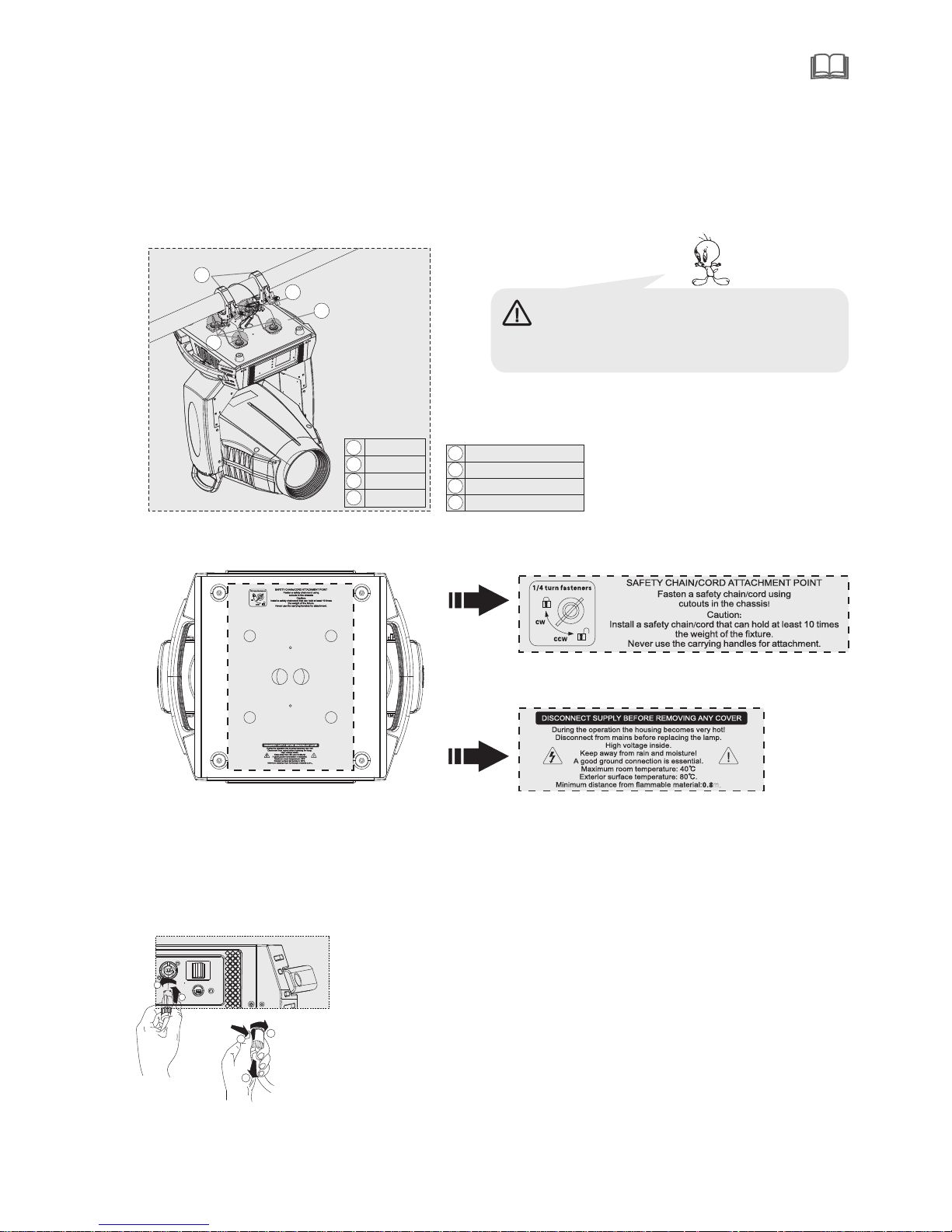
The pro jector ca n be placed d irectly on the stage floor or rigged in a ny orient ation on at russ with out alte ring it s operati on charac teristi cs.
For ove rhead use ,always i nstall a safety-rope that can hold at l east 10 tim es the weig ht of the fix ture.You
must on ly use safe ty-rope s with scre w on carabines.Pull the sa fety-ro pe throug h the two apertur es on the
botto m of the base a nd over the t russing s ystem etc .
1
2
3
4
Warning: it is nec essary to m ake sure th at
the ins tallati on locati on is perfectly appropri ate,
and the i nstalla tion loca tion is safe and reliable.
mount ing plate
secur e chain
omega h older
Lock ca tch
4.3 Power supply connection and cut off
Conne ct the ligh t source to t he main pow er source with the plug of the power cord , or cut off t he power
suppl y:
Conne ction: ac cording t o procedures, the power pl ug and sock et is inser ted into th e groove on e one
align ment, rot ation.
Cut off: according to procedur es, press t he button o n the rotat ing plug, p ull out.
1
2
3
1
2
2
4
旋钮
灯钩
保险 绳
底板
1
2
3
4
1
3
Page 8
6
2 1
3
2 1
3
5 1
4 2
3
5 1
4 2
3
5 1
4 2
3
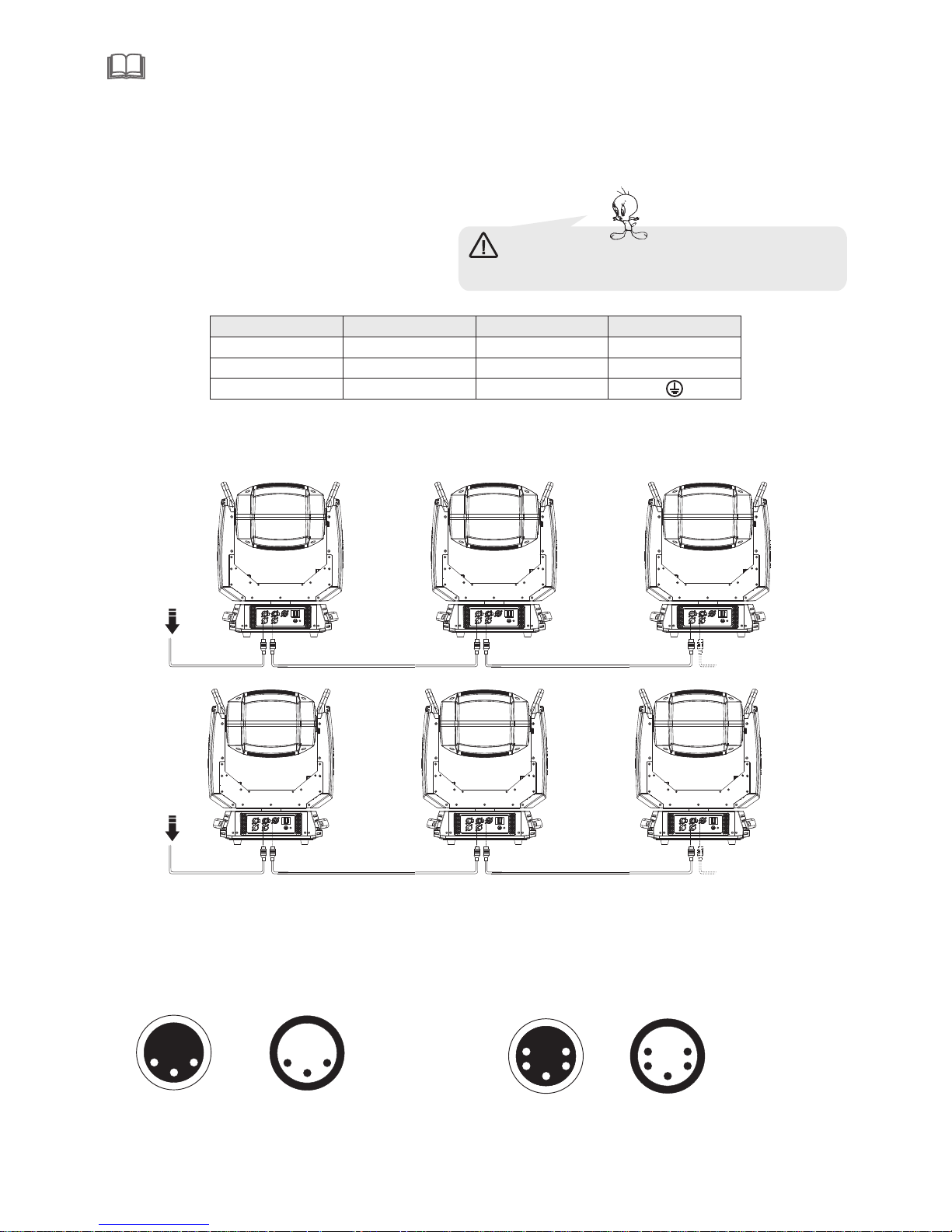
1: Gr ound
2: Si gnal( - )
3: Si gnal( + )
1: Gr ound
2: Si gnal( - )
3: Si gnal( + )
4: N. A.
5: N. A.
2 1
3
5 1
4 2
3
4.5 DMX-512 connection/connection between fixtures
Only us e stereo sh ieded cab le and 3-pin XLR-plugs and c onnecto rs in order t o connect .
Warni ng: please verify the powe r of the powe r
suppl y equipme nt prior to t he connection! Earth wire
must be g rounded !
Caution
At the la st fixtur e,the DMX -cable ha s to be termi nated with a terminatou. solder a 120 r esistor b etween
signa l(-) and Si gnal (+) in to a 3-pin XLR-plug and plug i t in the DMX- output of t he last fix ture.
DMX iut put
3-pin X LR socket
DMX iut put
5-pin X LR socket
DMX out put
3-pin X LR socket
DMX out put
5-pin X LR socket
4.4 Power Connection
mains w ith the enc losed pow er cable and plug.
If you wi sh to chang e the power s upply set tings, see the chapter appendix Con nect the fi xture to th e
L
N
CABLE (EU) CABLE (US)
Pin
Brown Black Live
Yellow/G reen Green
Earth
Light b lue
White Neutr al
INTER NATIONAL
DMX51 2 DMX51 2
Page 9
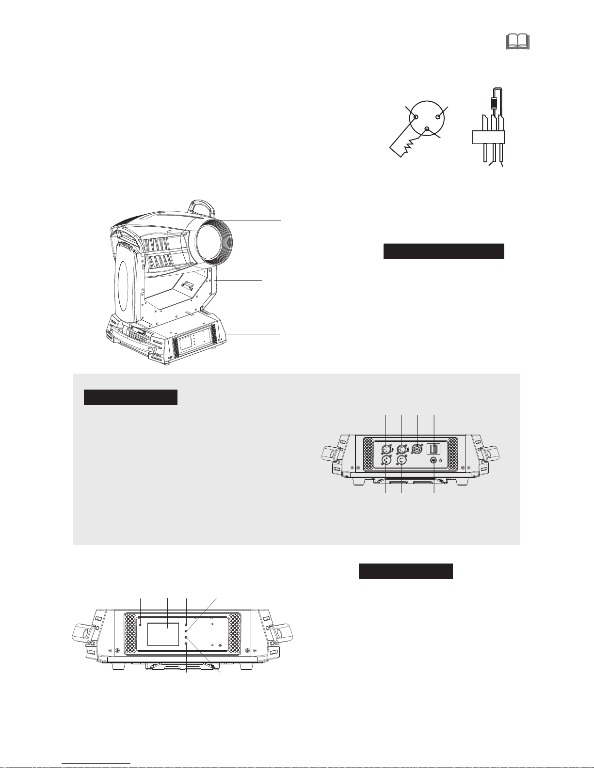
5.Description of the device
7
DMX Terminator Diagram
-For in stallat ions wher e the DMX cab le has to run a long distance or
is In an el ectrica lly noisy e nvironm ent it is recommended to use a
DMX ter minator. This help in prev enting co rruptio n of the sign al by
elect rical noi se. The DMX term inato r is si mply an XLR p lug witha
120 resis tor conne cted betw een pins 2 and pins3, which is t hen
plugg ed into a the o utput XLR s ocket of th e last ifxt ure in the chain.
Ω
1
2
3
12 0Ω
PIN2
PIN3
CINTROL PANEL
4 3
5 Power - i n
6
7 5- pi n XLR femal e
8 I
9 3
-pin XLR ma le
. - pi n XLR femal e
.
.Power sw itch
.
. nsurance se at
. - pi n XLR male
10.5
DESIGN CONSTIT UTION
1.Hea d
2.Arm
3.Bas e
11
13
16
14
15
12
13.Touc h screen( LCD displ ay)
14.MO DE button
15.UP button
16.DO WN button
BACK PANEL
11.
12.EN TER butto n
Statu s indicat or lamp
4
8
9
10
5
7
6
1
2
3
Page 10
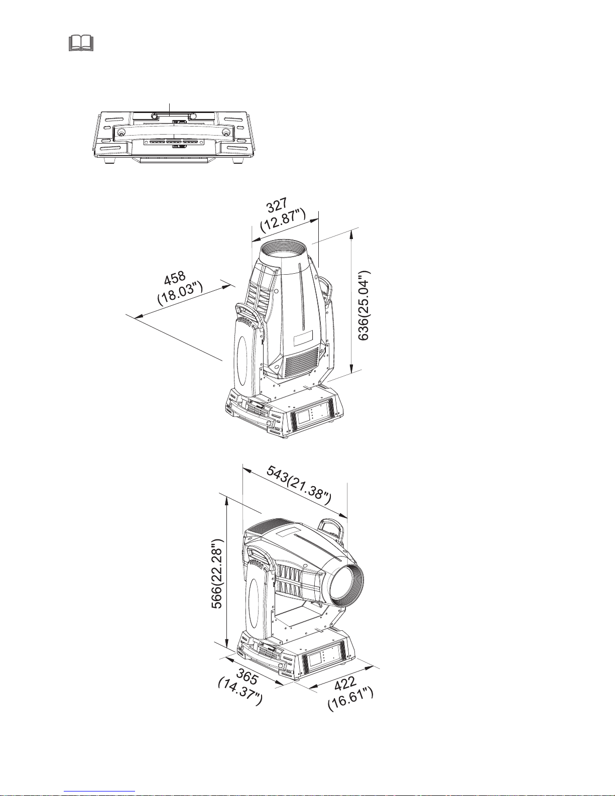
8
17
6.Dimension
17.WD MX wire
Page 11
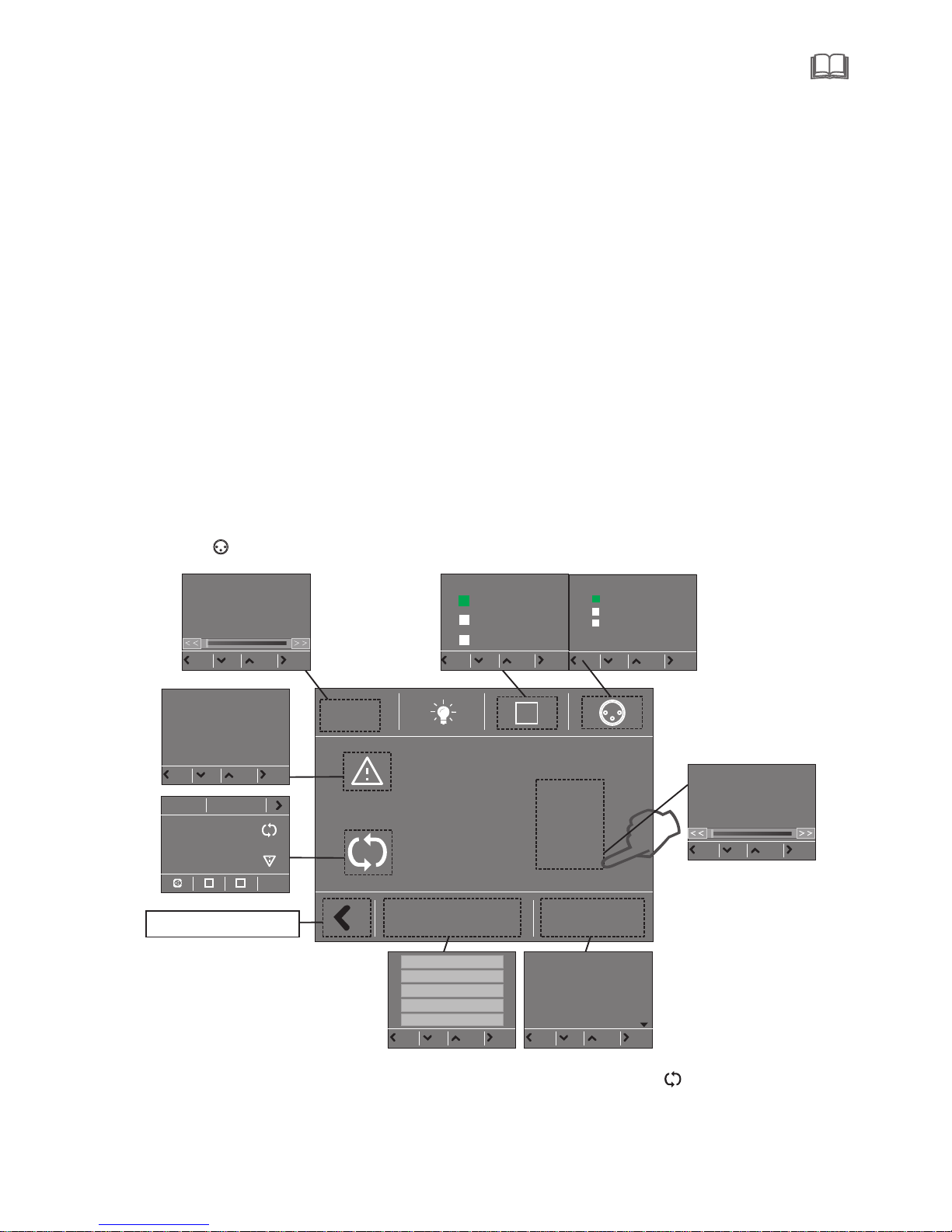
7.Display control
7.1 Navigation in the Menu
7.2 Display Operation
Using t he button s or touch sc reen, and t his can be simply and easily s et the addr ess code an d
code.
funct ions
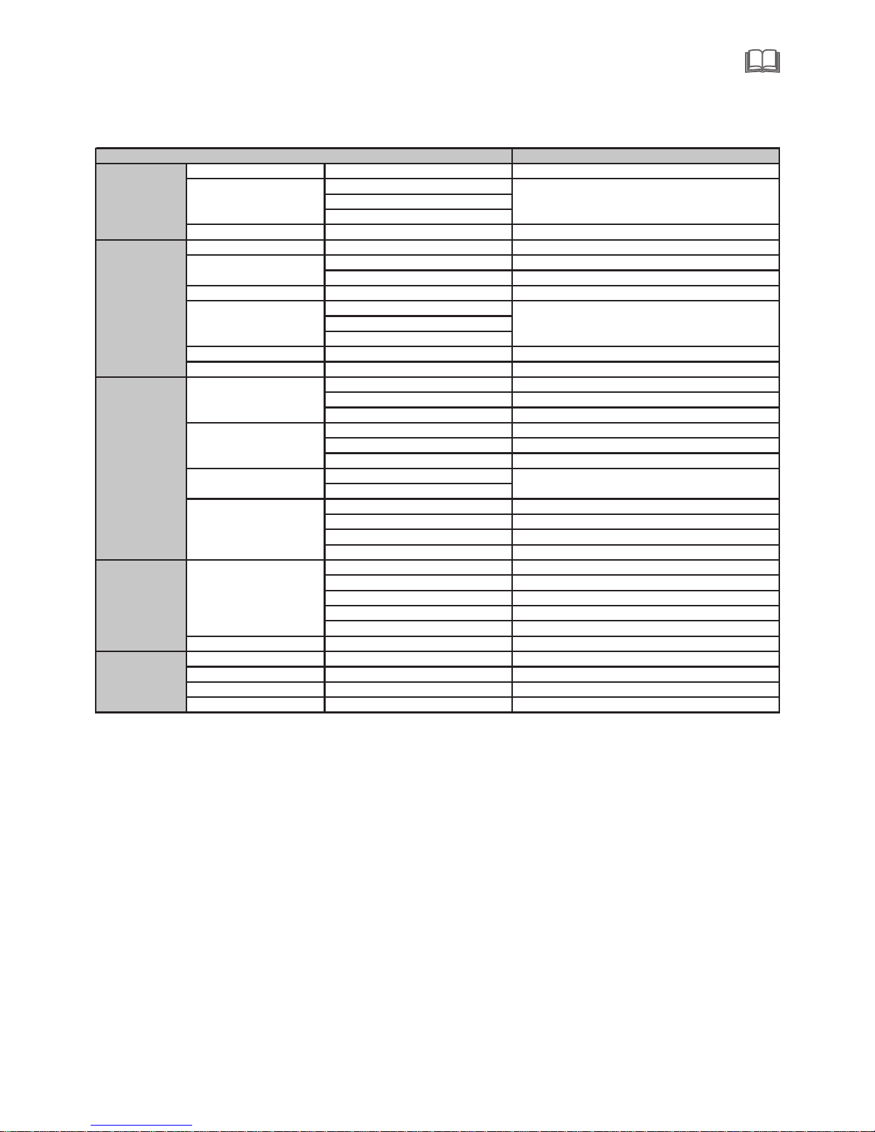
If you vi ew or modif y the light ing feature set, then pres s ENTER but ton, the di splay wil l enter the menu
inter face. Bot h there is sub menu correspo nding to th e functio nal opera tion of the m ain menu. E ach of the
menus i s represe ntative o f the specific features of t he lamp. Th e specifi c content s shows as th e table
menu be low.
Set or br owse ligh ting func tion, pre ss UP or DOWN butt on.
Press E NTER to sav e your chan ges or ente r the subme nu.Press the UP or DOWN can c hange the n umerical (increas e or decrease in va lue).
Press t he MODE but ton to retu rn to menu. S et a time 1 to 10 m inutes automatically exit menu in terface
and clo se the scre en.
Put thr ough powe r supply, open the power swi tch of lamp s and lante rns, disp lay show th e company
websi te. Accord ing to the ma in interf ace, as shown in figure:
In the ma in interf ace, pres s "MODE" bu tton to vie w the softw are version, press the "UP " "DOWN" ca n modify t he DMX addr ess.
If the sc reen " " icon i s green,s aid DMX sig nal conne ction is normal, this state can be used t o check thelamp s and lante rns and con nection between the cont rol table i s normal.
LOGO
9
This la mp can be set t o turn off the automatic fl ip screen f unction , touch thi s " “ icon can be m anually
flip sc reen.
menu interface
E1 2 :B u s Er r 1 0 1
E1 5 :B a l la s t E rr o r 0 7
E1 7 :B D 1 B US E r r or 9 9
E1 8 :B D 2 B US E r r or 9 9
E1 9 :B D 3 B US E r r or 9 9
Mod e Ent erUp Dow n
00 1
1
00 1 - 0 21Se t t i n gs
1
Main int er fa ce
A
001
1
001- 0 2 0
Set t in g s
1
Dmx In put
Wired Input
Wireless Input
Wireless In/
XLR out
Dmx In put
Mod e Ent erUp Dow n
Dmx Ad dress
0 10
Mod e Ent erUp Dow n
Set Up
Info ra mt ion
Pers on al ity
Manu al C on trol
Adva nc ed
Mod e Ent erUp Dow n
Fixt ure ID
00 10
Chan ne l Mo de
Mode1 1- 24
Mode2 1- 24
Mode3 1- 27
Mod e Ent erUp Dow nMod e Ent erUp Dow n
P
r
e
s
s
t
h
is
a
r
ea
f
o
r
2
s
e
c
o
n
ds
t
o
m
o
d
if
y
t
h
e
D
M
X
a
d
dr
e
s
s
.
Main interface
Can v iew the c ompan y LOGO, web
sit e, hard ware, s oftwa re vers ion, da te.
CH-001: 000.0% 000
CH-002:PAN Fine 0 00.0% 000
CH-003:Tilt 000.0% 000
CH-004:Tilt Fine 000.0% 000
CH-005:Cyan 000.0% 000
CH-006:Magenta 000.0% 000
CH-0 07:Yellow 000.0% 000
PAN
Mod e Ent erUp Dow n
Page 12
10
CODE
ERRO INFO CHECK MEASURMENT NOTE
E001 SpiFlashError Check the welding of memory IC
E002 Program Err 1 Check the welding of Chip
E003 Program Err 2 Check the welding of master IC EP3C
E005 BD1Init Error
E006 BD2Init Error
E007 BD3Init Error
E012 BusErr Check main cable ABAB(485) chip
E014 SPDError Check the welding of master IC
E017 BD1 BUS Error
E018 BD2 BUS Error
E019 BD3 BUS Error
E021 Pan FB. Err
E023 Tilt FB. Err
E022 Pan Zero Err
E024 Tilt Zero Err
E025 Prism Err1
E026 Prism Err2
E027 R.Gobo Err1
E028 R.Gobo Err2
E029 A.Gobo Err
E031 Zoom Err
E032 Focus Err
E033 St. Gobo Err
E034 ColourW. Err
E035 Iris Err
E036 Cyan Err
E037 Magenta Err
E038 Yellow Err
E039 CTO Err
E040 Frost Err
E042 B.Fan1 Error
E044 B.Fan2 Error
E053 L.Fan1 Error
E055 L.Fan2 Error
Check the fan of head
Check if the fan(80) of the lamp holder is working
Check the light coupling line, optical coupling switch and a plate of
the relative position measurement
Check cable of sensor, distance and location of ,magnets and sensor
RESET
ERROR
Check the communication signal 485& 485 chip & memory IC
Check the communication signal& welding of communication chip
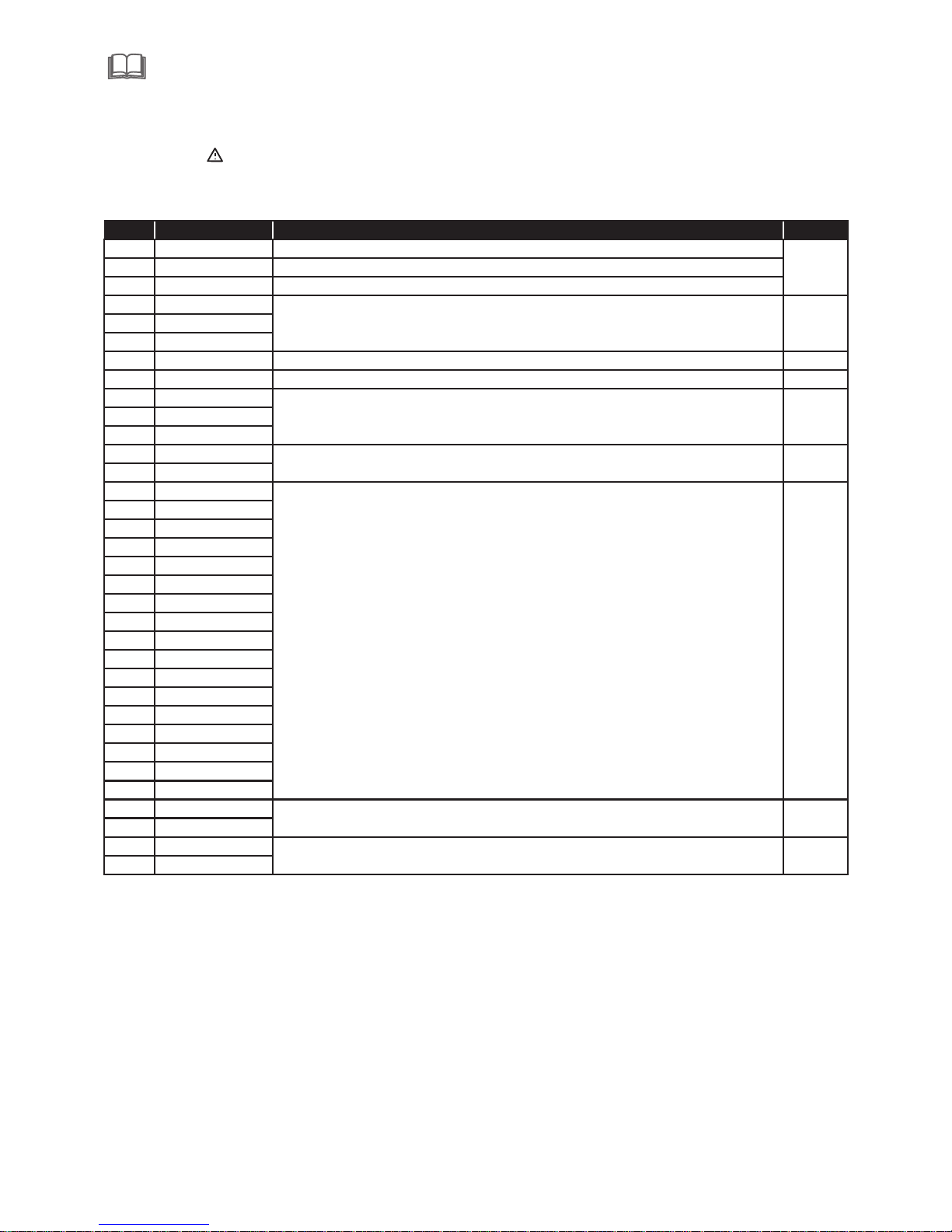
*Clic k on the main m enu of the ic on and valu e to view set of the relevant lighting in formati on. If ther e is
symbo l of the " " on the d isplay, it indicates that the devic e may be wron g , if the symb ol was blue , the
conte nts are err ors appea red, clic k to clear. Wh en the symbol is yellow, you ca n click on th e view and
accor ding to the r eferenc es inform ation to mo dify, If there is a ny doubt, p lease con sult the re levant
techn ical pers onnel. (- for detai ls see attached table).
Page 13
11
7.3 Unit Menu
Remark
Dmx Address 001~XXX Dmx Address
Mode1 1~24
Mode2 1~24
Mode3 1~27
Fixture Id 0001~9999 Lamps address
Fixture Times XXXXX h XX m Total working hours
Led Times XXXXh XXm Led working hours
Reset Led Time Reset Led Time
Error List Error details
BOARD 1: XX.XX%
BOARD 2: XX.XX%
BOARD 3: XX.XX%
Fans Monitor Fans Monitor
DMX Values DMX Values
Pan Reverse ON/OFF Pan Reverse(defaul OFF)
Tilt Reverse ON/OFF Tilt Reverse(defaul OFF)
Feedback ON/OFF Pan/Tilt Auto Switch(defaul ON)
Wired Input Wired Input(defaul)
Wireless Input Wireless Input
Wireless In/XLR out Wireless In/XLR out
English
Chinese
Brightness Brightness
Screen Time out 0-10m Screen Time out
Touch Screen ON/OFF Touch Screen(defaul OFF)
Auto Screen ON/OFF Auto Screen(defaul ON)
Reset ALL
Reset Pan/Tilt
Reset Colour
Reset Gobo
Reset other
Channel Chanel Testing
Calibration lnput Password XXXX Chanel Adgusting
Factory Default ON/OFF Reset to orignal parameters
Touch Calibration Touch screen adjusting
Firware UP date Firware UP date
Screen
Manual
Control
Reset
Language language choice
Information
LED Times
Diagnosis Diagnosis
Pan/Tilt
Dmx Input
Advanced
Personality
Set up Channel Mode default Mode1
Page 14
12
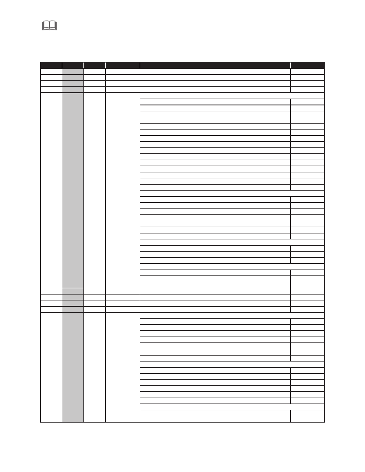
8.DMX protocol
Mode 1Mode 2Mode 3 Fade Type Function Dmx Value
1 20 23 Pan Pan 0-255
2 21 24 Pan Fime Pan Fime 0-255
3 22 25 Tilt Tilt 0-255
4 23 26 Tilt Fime Tilt Fime 0-255
Empty position 0
White→ red 1-19
red 20
red→green 21-39
green 40
green→blue 41-59
blue 60
blue→orange 61-79
orange 80
orange→pink 81-99
pink 100
pink→CTO 101-119
CTO 120
CTO→fluorescence 121-139
fluorescence 140
red 141-146
green 147-152
blue 153-158
orange 159-164
pink 165-170
CTO 171-182
fluorescence 183-188
CW,fast or slow 189-213
stop 214-219
CCW,slow or fast 220-243
Random slow color 244-247
Random medium color 248-251
Random fast color 252-255
6 3 4 Cyan Linear Cyan movement 0-255
7 4 5 Magenta Linear Magenta movement 0-255
8 5 6 Yellow Linear Yellow movement 0-255
9 6 7 CTO Linear CTO movement 0-255
Empty position 0-4
Gobo 1 5-7
Gobo 2 8-10
Gobo 3 11-13
Gobo 4 14-16
Gobo 5 17-19
Gobo 6 21-23
Gobo 1 24-26
Gobo 2 27-29
Gobo 3 30-32
Gobo 4 33-35
Gobo 5 36-39
Gobo 6 40-42
Gobo 1 43-72
Gobo 2 73-102
Rotation
Gobo
Select
9810
color
RotaTing gobo Select 11/9/10
Rotation - set rotation on channel 11/9/10
Gobo Shakes at variable speed from slow to fast 11/9/10
Whatever Position
5 7 8
Single step rotation
The color of the water
Random color
Page 15
13
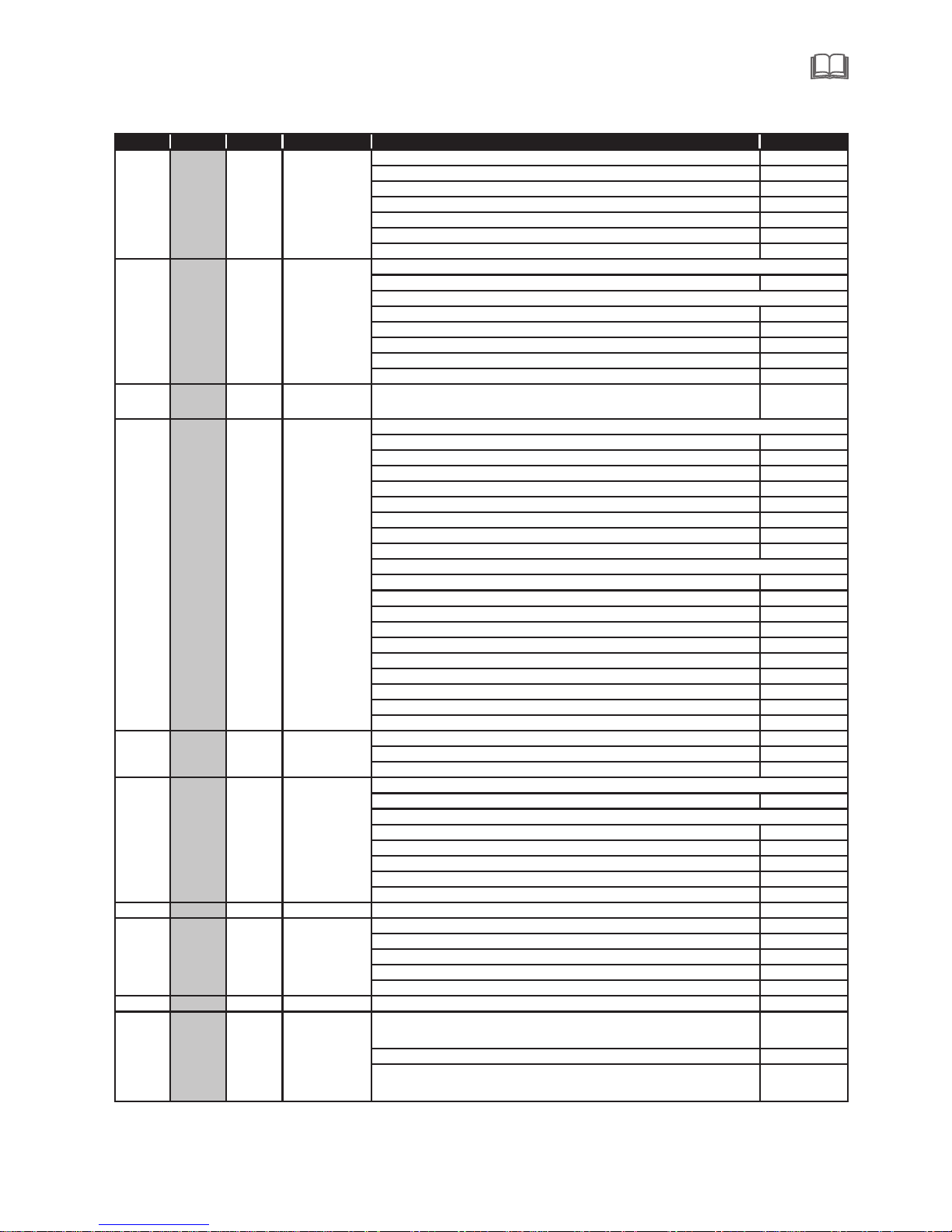
Gobo 3 103-132
Gobo 4 133-162
Gobo 5 163-192
Gobo 6 193-222
Forwards gobo wheel rotation from fast to slow 223-237
No rotation 238-240
Backwards gobo wheel rotation from slow to fast 241-255
Gobo indexing 0-255
No rotation 0-2
Forwards gobo rotation from fast to slow 3-126
No rotation 127-129
Backwards gobo rotation from slow to fast 130-253
No rotation 254-255
12 10 11
Fine Gobo
Rotation
Fine Gobo Rotation 0-255
Unused Range 0-9
Gobo 1 10-19
Gobo 2 20-29
Gobo 3 30-39
Gobo 4 40-49
Gobo 5 50-59
Gobo 6 60-69
Gobo 7 70-79
Gobo 1 80-99
Gobo 2 100-119
Gobo 3 120-139
Gobo 4 140-159
Gobo 5 160-179
Gobo 6 180-199
Gobo 7 200-219
Forwards gobo wheel rotation from fast to slow 220-236
No rotation 237-238
Backwards gobo wheel rotation from slow to fast 239-255
Prism out 0-10
Prism indexing - set position on channel 15/16/17 11-138
Prism rotation - set position on channel 15/16/17 139-255
Prism indexing 0-255
No rotation 0-2
Forwards Prism rotation from fast to slow 3-126
No rotation 127-129
Backwards Prism rotation from slow to fast 130-253
No rotation 254-255
16 14 15 Frost Focus moves linearly into the light beam 0-255
Open →closed 0-131
Slow pulsation fast pulsation 132-171
Slow open,slow close- fast open,fast close 172-211
Fast open,fast close -fast open,fast close 212-251
Close 252-255
18 12 13 Animation Linear Animation disk insertion 0-255
Continuous Animation disk clockwise rotation at
linearly variable speed from fast to slow
0-124
Stop rotation 125-130
Continuous Animation disk couneter-clockwise
rotation at linearly variable speed from slow to fast
131-255
Rotation
Gobo
Select
11
14
15 17
1615
10 8 9
Animation
disk
rotation
Static
gono
Change
Rot. gobo
indexing
and
rotation
141319
1213
Gobo rotation - set position on channel 10/8/9
Iris
Gobo indexing - set position on channel 10/8/9
9 10
16
Prism
rotation
Prism
insertion
Positioning
Shaking gobos from slow to fast
Prism indexing - set position on channel 14/15/16
Prism rotation - set position on channel 14/15/16
17 1817
11
Mode1 Mode2 Mode3 Fade Type Function Dmx Value
Page 16
14
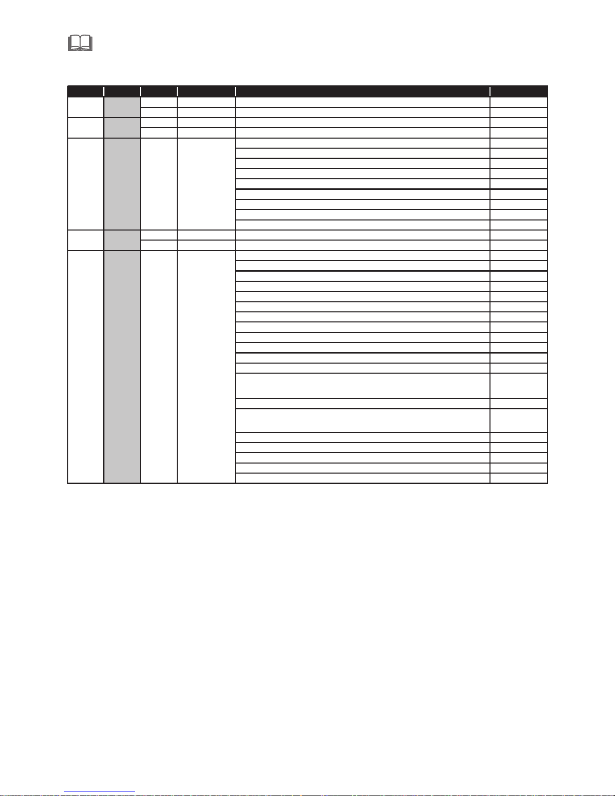
Mode1 Mode2 Mode3 Fade Type Function Dmx Value
19 Zoom Zoom linearly moves from narrow to wide beam 0-255
20 Zoom Fine Fine Zoom positioning
21 Focus Focus moves linearly from far to near position 0-255
22 Focus Fine Fine focus positioning 0-255
Close 0-3
STROBE SLOW→FAST 4-103
OPen 104-107
PULSATION SLOW→FAST 108-207
Open 208-212
Random slow Strobe 213-225
Random medium Strobe 226-238
Random fast Strobe 239-251
Open 252-255
2 Dimmer Dimmer 0-100% 0-255
3 Dimmer Dimmer Fime 0-255
Unused Range 0-9
Reset Complete -3 sec 10-14
Reset CMY, CTO and color wheel only-3 sec. 15-19
Reset Other -3 sec 20-24
Reset Pan/Tilt -3 sec 25-29
Reset Gobo -3 sec 30-34
Dimmer Curve 1 =linear(1 sec) 35-39
Dimmer Curve 2 =Gamma1.5(1 sec) 40-44
Dimmer Curve 3 =Gamma2.0(1 sec) 45-49
Dimmer Curve 4 =S(1 sec) 50-54
Unused Range 55-104
Disable zoom/focuslinking-1 sec. 105-109
Enable zoom/focus linking,near distance(5meters)
(default setting)-1 sec.
110-114
Enable zoom/focus 115-119
Enable zoom/focus linking, far distance(12meters) -
1 sec.
120-124
Unused Range 125-224
Autofocus priority rotation gobo 225-229
Autofocus priority FX wheel 230-234
autofocus priority Iris 235-239
Unused Range 240-255
Function
2
272424
22 1
Stopper/
Strobe
1
23
21
18
19
20
Page 17

15
9.Maintance and cleaning
It is abs olutely e ssentia l that the fi xture is ke pt clean and that dust,dir t and smoke f luid resi dues mus t not
build up on or with in the fixt ure. Othe rwise, the fixtures ligh t-outpu t will be sig nifican tly reduc ed. Regul ar
clean ing will no t only ensu re the maximum light-out put, but wi ll also all ow the fixt ure to func tion re liably
throu gh out its li fe. A soft lint- free cloth moistened with any good gl ass clean ing fluid i s recomme nded,
under n o circum st ances sho uld alcohol or solvents be u sed!
The fr ont objective lens will re quire wee kly clean ing as smok e-fluid t ends to bui lding up residues,redu cing the l ight-ou tput very q uickly.The co oling-f ans shoul d be cleane d monthly.
The go bos may be cleane d with a soft b rush,Th e interio r of the fixt ure shoul d be cleane d at least an nually usi nga vacuu m-clean er or an air-jet.
Ther e are no serviceable parts i nside the d evice exc ept for the l amp and the f use.
Repla cing the fu se: If the la mp burns ou t,the fin e-wire fuse of the device mi ght fuse, too.Onl y replace t he
fuse by a f use of same t ype and rat ing.Bef ore replacing the fuse,u nplug mai ns lead.
Maint enance an d mainten ance of the operation, ple ase conta ct the manu facture r or distri butor.
DANGER:Disconnect fro m the mains b efore sta rting any maintenance work.
10.1 Electrical paramters
10.Electric equipment specification
SOURC E:
POWER :
VOLTAGE:
440W Wh ite LED
750W
AC100 -240V 50/ 60HZ
Color t emperat ure:8000K
10.2 Weight and dimensions
Dimen sions:543 X4 X5
NET WE IGHT:36Kg
Dimen sions(Car ton packa ge): 657X567X661 mm
WEIGH T5Carto n package
8 66
( ): 42Kg
mm
10.3 Channel Characteristics
2.Scan: P an540°,Tilt 244°,Scan s peed adjustab le.Fixt ure could a uto reset .
3.Colou r wh ee l: one open +7colors.half-colo r effect s,CMY fun ction.
4.Gobo wh eel:one open+ 6 gobos.o ne , Fix gobo wh eel :one open+ 7gobos.
5.Prism s ystem:1 rotating of 8 faces.
6.Zoom: linear amplifier.
7.Focus :linear focus wi th auto fu nction.
8.Demme r:el ectroni c dimmi ng,lin ear dimme r.
9. Stro be:elec tronic st robe,wi th strobe mo de of s ynchron istical ,pulse an d random.
10. Fir e wh ee l:fire wh eel with ro tation.
1.Chann el:24、24、27 DM X- 512.
10.4 Menu Function
1. .Touch scr een,Engli sh/Chinese men u
Page 18
16
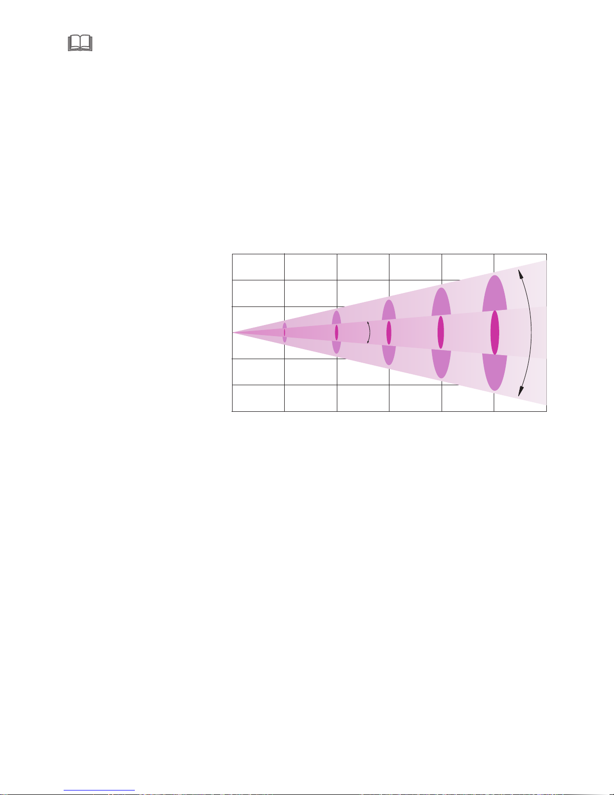
10.5 light table
2.Eac h DMX Value d isplaya ble.
3. Time of a utomati c turning off is a ble to set on t he displa y,when operating pan/t ilt,Col or and gobo s,
gobos , strobe ar e turn off and abl e to set free ly.
4. Disp lay the tim e using of lighting featur e and lamp as w ell as the ti mes of turn ing on for la mp.
5. You can swi tch on and off the lamp via th e control p anel or via y our DMX con troller. It mus t be noted
that it h as to be cold b efore re-str icking.
6.Aft er the DMX signa l is discon nected, t he displa y will be bright and dark.
7.Sof tware upg rade func tion.
Flare d iameter (m)
The min imum Angle 8 .6°Flare di ameter(m)
Maxim um Angle36°F lare diameter(m)
Proje ction dis tance(m )
10
15
20
Φ1. 5 2
Φ0. 7 6
Φ2. 2 8
Φ6. 4 8
Φ3. 2 4
Φ9. 7 2
2130
532
25
Φ3. 0 4
Φ12 . 9 6
132
236
28920
12517 31295563
5
Φ3. 8 4
Φ16 . 2
85
2002
36°
36 L ux)°Illum inance( Lux) (
8.6°Ill uminanc e( Lux) (L ux)
8.6°
Page 19
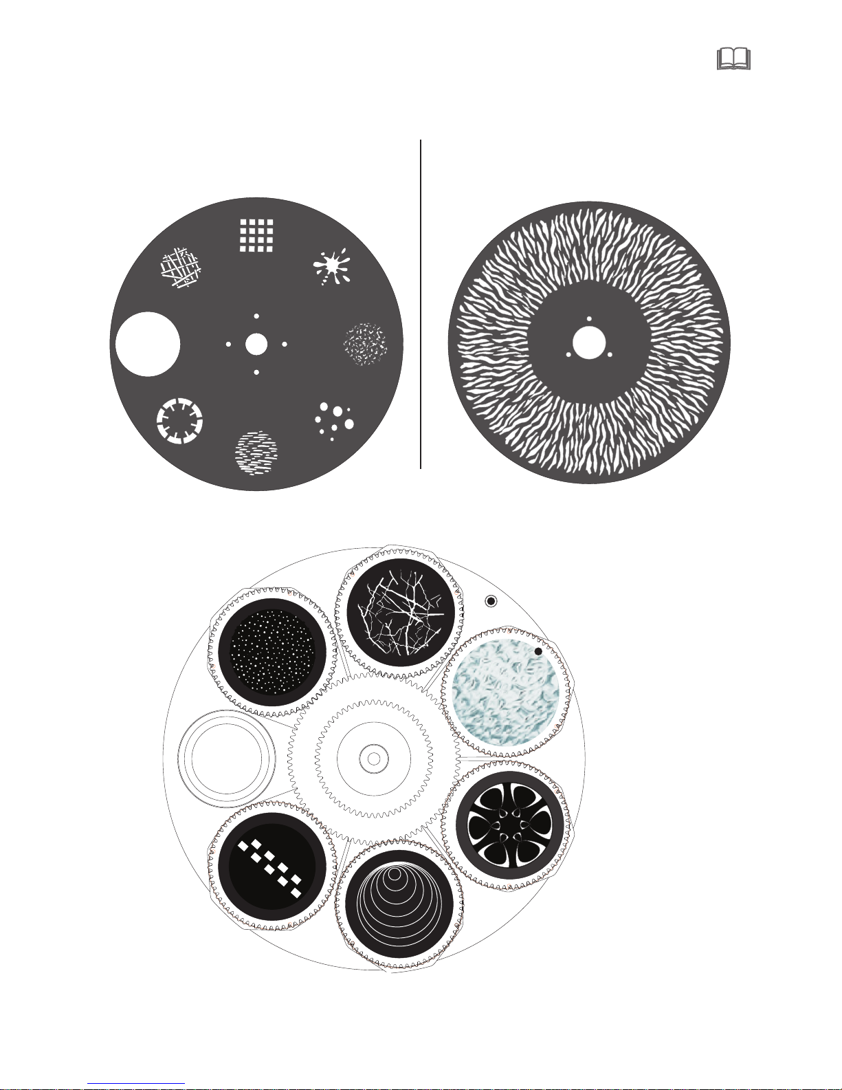
17
Effe ct wheel
Rgobo w heel
Glass des ign , Ins ide diameter3 4.7 mm, effec tive diame ter 3 0mm .
10.6 Gobo wheel
Integra,I nsi de di ameter 162 mm, effec tiv e
diamete r 25. 5mm
Integra,I nsi de di ameter mm,effectiv e
diamete r 124 mm
130
Fix gob o wheel
Page 20
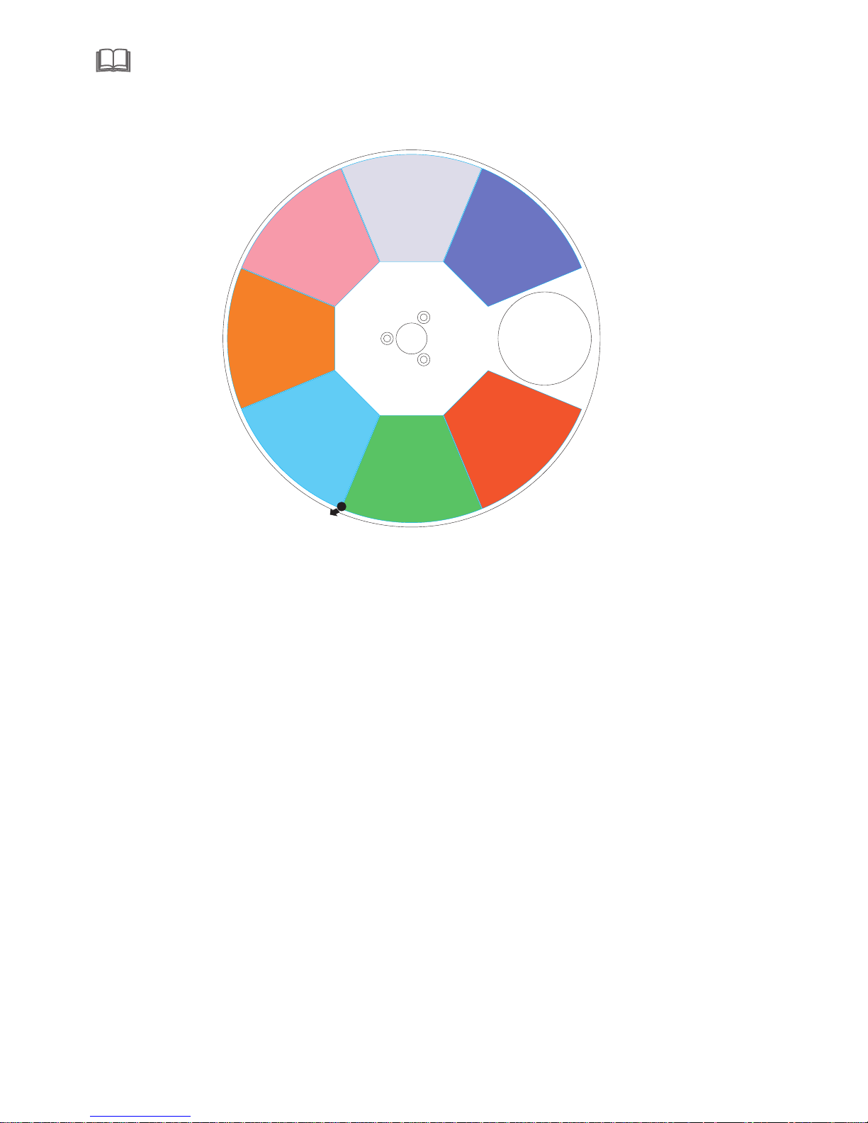
18
10.7 Color wh eel
CTO
Magn et s
Pink
blue
red
Green
orang e
Fluor escent
Page 21
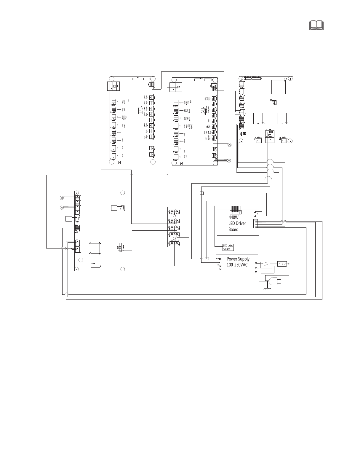
19
Note: The above inform ati on is f or re ference only, the final interpreta tio n is be lon g to ma nufacturer.
11.Electronic drawing
L
N
AC
IN
DC48V
DC5V
+
-
Titl
Motor
Pan
Motor
Titl EN
Pan EN
Titl Sensor
Pan Sensor
L
N
Three Phase Motor Driver Board
L
+
-
G
LED
Fan
F2
LED
Fan
F1
LED Control
-
Cyan
Magnta
Yellow
Static
Gobo
Wheel
M1
M2
M3
M4
M5
M6
M7
M8
(YM)
(MM)
Magnta
(CM)
(GM)
M1
M2
M3
M4
M5
M6
M7
M8
Frost
Motor
Iris
(4PM)
(FO)
(ZO)
(4PM)
Power Supply
Power Supply
+
Color
Wheel
(DGM)
(IR)
Iris
(CM)
(CTOM)
60
Fan
80
Fan
Power Supply
RS485
RS485
RS485
+3V3
NTCNTC+
PWM2
PWM1
GND
Battery
DMX
FUSE
Page 22

 Loading...