

Page 1
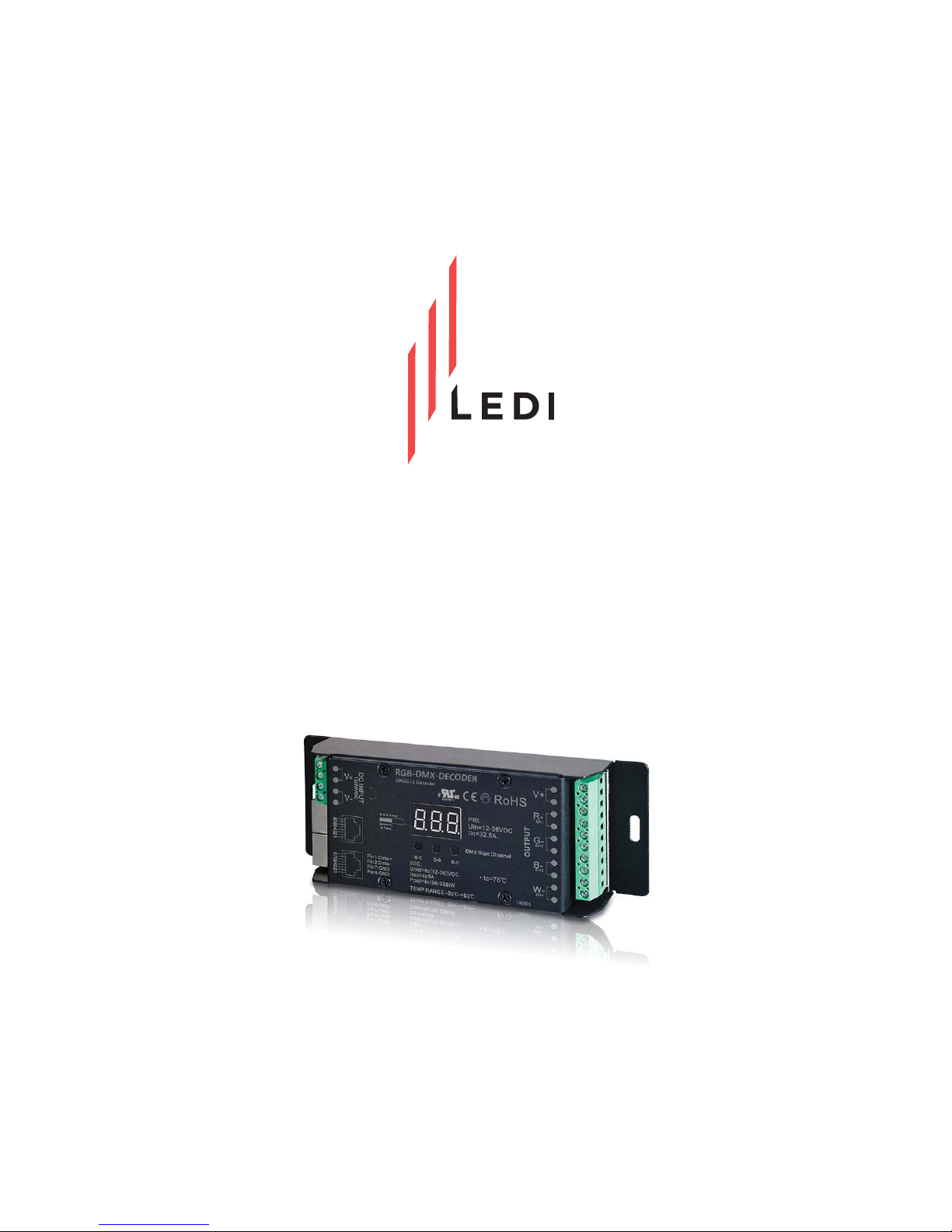
Installation
Instructions
for the RGB DMX Decoder
#RGB-DMX-DECODER
Page 2
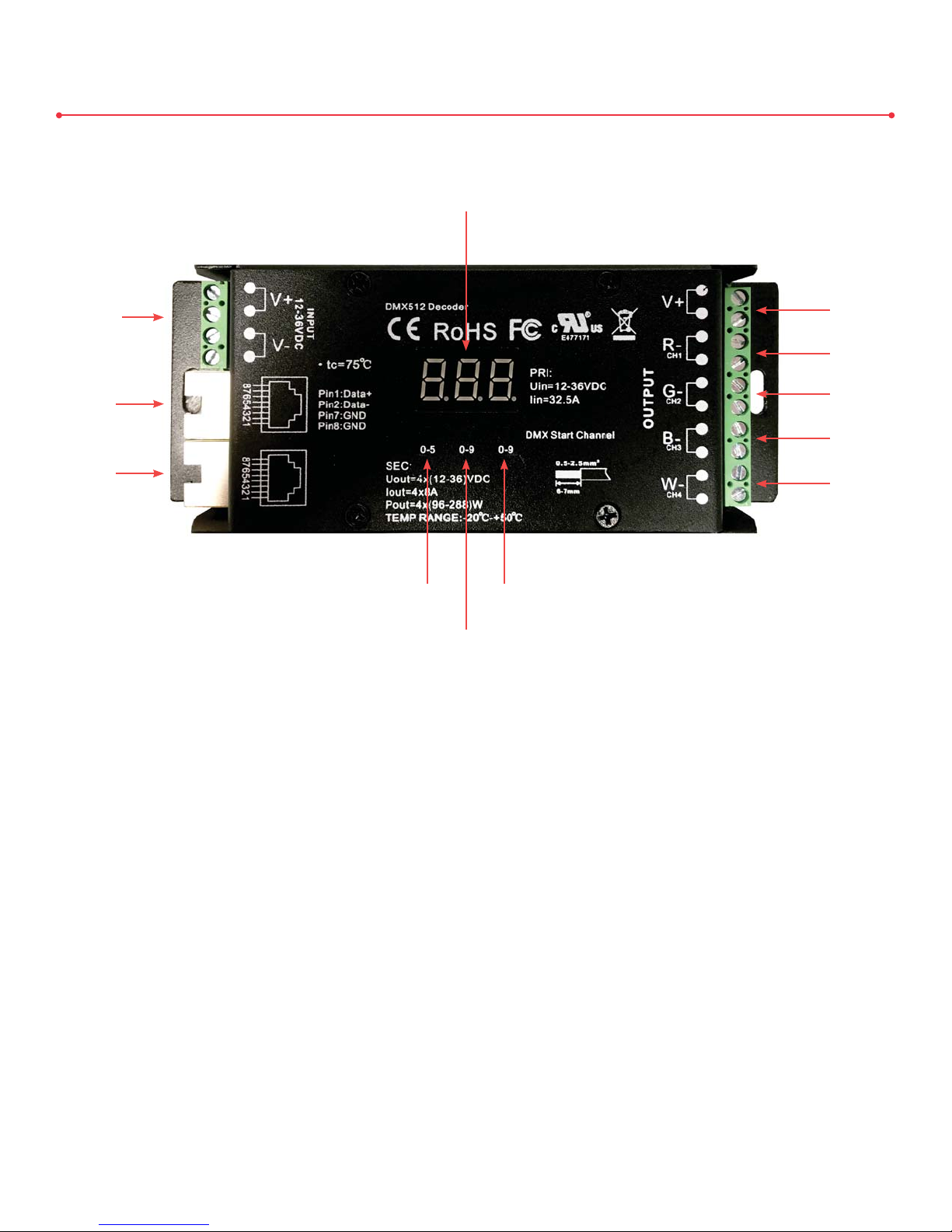
RGB DMX Decoder Overview
Digital Display
for DMX Channels
12-36V DC
Input Terminals
Ethernet
(CAT-5)
Input Port
Ethernet
(CAT-5)
Output Port
0-5
Channel
Selection
Channel
Selection
0-9
0-9
Channel
Selection
• 12-36V DC Input Terminals - Input terminals for a low voltage, electronic DC driver
“V+” Terminal
“R” Terminal
(Red)
“G” Terminal
(Green)
“B” Terminal
(Blue)
“W” Terminal
(White)
• Digital Display for DMX Channels - Displays the current DMX channel selected
• “V+” Terminal - Terminal for the positive (+) wire from an RGB connector
• “R” Terminal (Red) - Terminal for the red wire from an RGB connector
• “G” Terminal (Green) - Terminal for the green wire from an RGB connector
• “B” Terminal (Blue) - Terminal for the blue wire from an RGB connector
• “W” Terminal (White) - Terminal for the wiring from a static white run of tape light
• Ethernet (CAT-5) Input Port - Port for receiving CAT-5 data
• Ethernet (CAT-5) Output Port - Port for sending CAT-5 data
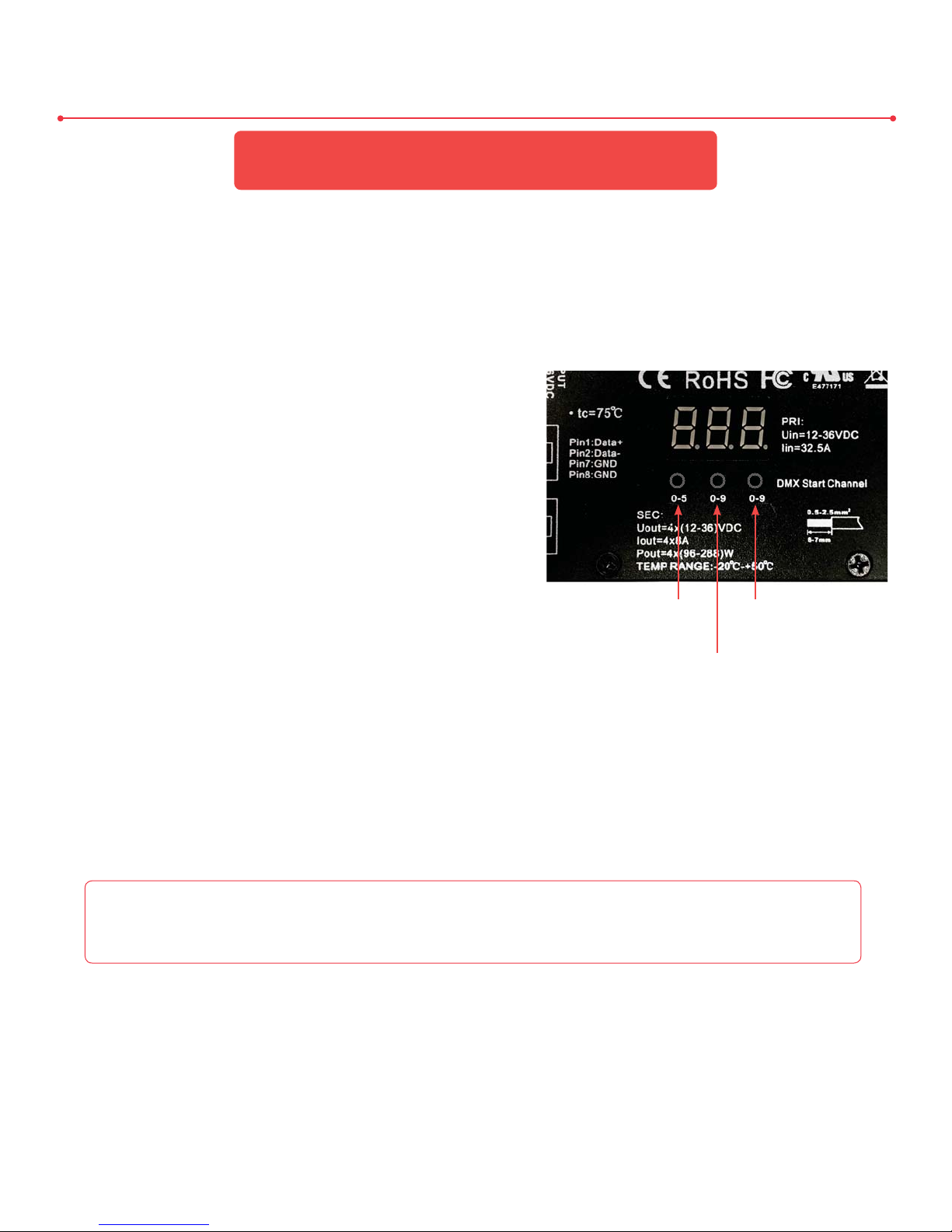
• 0-5 Channel Selection (Hundreds Place) - Cycle through values 0-5 in the hundreds place only
• 0-9 Channel Selection (Tens Place) - Cycle through values 0-9 in the tens place only
• 0-9 Channel Selection (Ones Place) - Cycle through values 0-9 in the ones place only
2
Version 05112017
Page 3

Installing the RGB DMX Decoder
Parts Needed Tools Needed
x1 or More RGB DMX Decoder(s)
x1 RGB DMX Controller*
x1 or More CAT-5 Cable(s)*
x1 or More RGB Hardwire Connector(s)*
x1 or More 24V DC Electronic Driver(s)*
x1 or More Run(s) of RGB Tape Light*
x2 or More Wire Nuts*
x1 RGB DMX Terminator**
*Items sold separately.
**Only needed if installing three or more RGB DMX Decoders.
RGB DMX Terminators are sold separately.
IMPORTANT! ENSURE ALL AC POWER HAS BEEN
SHUT OFF BEFORE PERFORMING THIS INSTALLATION!
Using an RGB Hardwire Connector, wire the stripped ends of the connector
to the OUTPUT terminals of the RGB DMX Decoder. Use the ”V+” terminal
for the gray (or black) wire, the “R” terminal for the red wire, the “G” terminal
Additional Terminal
Additional Terminal
for the green wire, and the “B” terminal for the blue wire. Screw down each
terminal with a mini flathead screwdriver to secure the wire.
x1 Mini Flathead Screwdriver
x1 Wire Strippers
To RGB DMX Controller
Additional Terminal
Additional Terminal
Not Used
Not Used
1
2
3
Note: The “W” terminals will not be used.
Tip: In the event you need to wire more than one RGB Hardwire Connector to the
RGB DMX Decoder, you may use the additional terminal of each channel (V+, R, G,
B) for any additonal RGB tape light runs . You may wire multiple runs of RGB tape
light to each terminal; however, ensure the terminals allow enough space for each
wire.
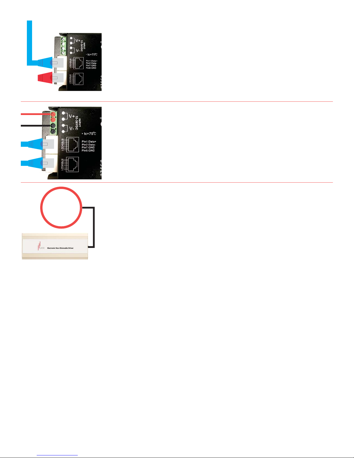
Connect the CAT-5 cable from your RGB DMX Controller to
the INPUT Ethernet port.
If wiring additional RGB DMX Decoders, connect a CAT-5
cable to the OUTPUT Ethernet port of the RGB DMX Decoder
you just installed. Connect the same CAT-5 cable to the INPUT
Ethernet port of your next RGB DMX Decoder. Repeat this
process for any additional RGB DMX Decoders you install.
3
Version 05112017
Page 4
120-277V
AC Power
4
5
6
If installing 3 or more RGB DMX Decoders, an RGB DMX
Terminator is needed to terminate the signal. Connect the RGB
DMX Terminator to your last RGB DMX Decoder (opposite of
your RGB DMX Controller, which is considered the first) to the
OUTPUT Ethernet port.
Wire the low voltage leads from your 24V DC Electronic Driver
to the 12-36V DC INPUT terminals. Use the “V+” terminal for
your positive wire, and the “V-” terminal for your negative
wire. Repeat this process for each RGB DMX Decoder you’ve
installed.
Wire the line voltage ends of your 24V DC Electronic
Driver(s) to 120-277V AC power.
ATTENTION
1. This product should be installed and serviced by a trained professional.
2. This product is NOT waterproof and is intended for an indoor and dry environment only.
3. This product should be placed in a well-ventilated area. Excess heat and poor airflow could damage the product.
4. Please ensure all output voltages comply with the working voltage of this product.
5. Please ensure the appropriately sized wire is used from the RGB DMX Decoder to other compatible components.
6. Please do not attempt any modifications or repairs on this product. If a replacement unit is needed, please contact LEDI at (832) 717-2710.
7. This product has a 5 year limited warranty from the purchase date.
4
Version 05112017
Page 5
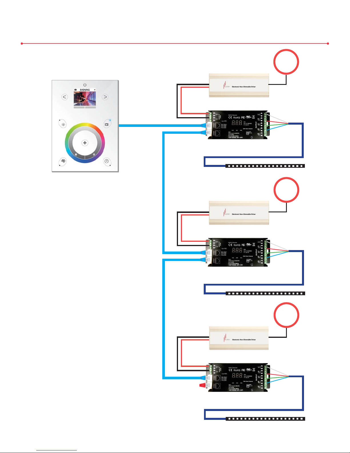
Complete System Wiring Diagram
120-277V
AC Power
RGB DMX Decoder
CAT- 5
RGB Hardwire Connector
RGB Tape Light
RGB DMX Stick 3 Controller
120-277V
CAT- 5
AC Power
RGB DMX Decoder
RGB Hardwire Connector
RGB Tape Light
CAT- 5
RGB DMX Decoder
RGB DMX
Terminator
120-277V
AC Power
5
RGB Hardwire Connector
RGB Tape Light
Version 05112017
Page 6
RGB DMX Decoder Addressing
NOTE: This section should only be used if using
a MULTI-ZONE RGB DMX CONTROLLER.
Introduction
The RGB DMX Decoder transfers data via the standard DMX512 protocol. There are 512
available channels, giving you the option to assign different sections of your RGB LED tape
light individually. Follow the instructions below to learn how to address each section.
Digital Display & Programming Buttons
There are three programming buttons positioned
below the digital display. See below for a
description of each. Refer to Figure 1A for a visual:
“Button 1” controls the hundreds place value and
can have a numeric value of 0-5.
“Button 2” controls the tens place value and can
Figure 1A
have a numeric value of 0-9.
“Button 3” controls the ones place value and can
have a numeric value of 0-9.
Hundreds
Place Value
“Button 1”
Place Value
“Button 2”
Tens
Ones
Place Value
“Button 3”
Instructions
Step 01:
Step 02A: Press and hold “Button 1” until the digital display begins to flash. While the digital
First, the DMX Start Channel must be set to channel 4. Press and hold “Button 2”
and “Button 3” until the digital display begins to flash. While the digital display is
flashing, press “Button 1” to scroll through each DMX Start Channel. When you’ve
landed on channel 4 (the digital display will read “4ch”), press and hold “Button 1”
to save your selection. Repeat this step for each RGB DMX Decoder.
NOTE: FOLLOW “STEP 02A” IF YOU WOULD LIKE EACH SECTION OF RGB LED
TAPE LIGHT TO OPERATE THE SAME. FOLLOW “STEP 02B” IF YOU WOULD LIKE
EACH SECTION OF RGB LED TAPE LIGHT TO OPERATE SEPERATELY.
display is flashing, press “Button 1” until the numeric value reads “0” (zero). Then,
press “Button 2” until the numeric value reads “0” (zero), as well. Finally, press
“Button 3” until the numeric value reads “1” (one). Press and hold “Button 1” to
save your selection. The digital display should read “001”. Repeat this process for
each RGB DMX Decoder. Once completed, each section of RGB LED tape light
will behave the same when operated by the RGB DMX Controller.
6
Version 05112017
Page 7

Step 02B:
First RGB DMX Decoder:
Press and hold “Button 1” until the digital display begins to flash. While the digital
display is flashing, press “Button 1” until the numeric value reads “0” (zero). Then,
press “Button 2” until the numeric value reads “0” (zero), as well. Finally, press
“Button 3” until the numeric value reads “1” (one). Press and hold “Button 1” to
save your selection. The digital display should read “001”, or address 1.
Second RGB DMX Decoder:
Repeat the same process you followed for the first RGB DMX Decoder, but instead
of setting the ones place value at “1” (one), set it to “2” by pressing “Button 3”
until the numeric value reads “2”. Press and hold “Button 1” to save your selection.
The digital display should read “002”, or address 2.
Any Additional RGB DMX Decoders:
Repeat the same process you followed for the second RGB DMX Decoder, setting
the address differently each time and in sequential order (ex: 003, 004, 005,
etc.). You may adjust the tens place value and/or the hundreds place value, if
need be (ex: 010, 100, 150, etc.).
Step 03:
Cycle through some different effects on you RGB DMX Controller to ensure each
section of RGB LED tape light behaves according to how you’ve addressed the
RGB DMX Decoders.
NOTE: If you notice sections of RGB LED tape light are cycling through effects slower than
other sections even though the sections are addressed the SAME, you may need to turn off the
delay setting for those RGB DMX Decoders. This can be done by simply holding “Button 1” and
“Button 3” until you see “P-c” flashing on the digital display. While “P-c” is still flashing, hold
down “Button 1” and “Button 3” again, until the digital display goes back to the address. Check
the sections of RGB LED tape light to ensure they are synchronized.
For additional assistance, please contact LEDI’s Design Department at
(832) 717-2710, or [email protected].
7
Version 05112017
 Loading...