

LedEngin LZ1-00NW05 User Manual

LedEngin, Inc.
High Luminous Efficacy
Neutral White LED Emitter
LZ1-00NW05
Key Features
High Luminous Efficacy 5W Neutral White LED
Ultra-small foot print – 4.4mm x 4.4mm x 3.2mm
Surface mount ceramic package with integrated glass lens
Very low Thermal Resistance (5.5°C/W)
Very high Luminous Flux density
Spatial color uniformity across radiation pattern
New industry standard for Lumen Maintenance (>90% at 100,000 Hours)
Autoclave complaint (JEDEC JESD22-A102-C)
JEDEC Level 2 for Moisture Sensitivity Level
Lead (Pb) free and RoHS compliant
Reflow solderable (up to 6 cycles)
Emitter available on Standard
or Miniature MCPCB (optional)
Typical Applications
General Lighting
Commercial Refrigeration
Office Lighting
Display Lighting
Accent & Task Lighting
Architectural Detail Lighting
Description
The LZ1-00NW05 Neutral White LED emitter provides 5W power in an extremely small
package. With a 4.4mm x 4.4mm x 3.2mm ultra-small footprint, this package provides
exceptional luminous flux density. LedEngin’s patent-pending thermally insulated phosphor
layer provides a spatially uniform color across the radiation pattern and a consistent CCT over
time and temperature. The high quality materials used in the package are chosen to optimize
light output and minimize stresses which results in monumental reliability and lumen
maintenance. The robust product design thrives in outdoor applications with high ambient
temperatures and high humidity.

Table of Contents
Product Nomenclature . . . . . . . . . . . . . . . . . . . . . . . . . . . . . . . . . . . . . . . . . . . . . . . . . . 3
Luminous Flux Binning. . . . . . . . . . . . . . . . . . . . . . . . . . . . . . . . . . . . . . . . . . . . . . . . . . 3
Forward Voltage Binning . . . . . . . . . . . . . . . . . . . . . . . . . . . . . . . . . . . . . . . . . . . . . . . . 3
Neutral White Chromaticity Binning . . . . . . . . . . . . . . . . . . . . . . . . . . . . . . . . . . . . . . . . 4
IPC/JEDEC Moisture Sensitivity . . . . . . . . . . . . . . . . . . . . . . . . . . . . . . . . . . . . . . . . . . 5
Average Lumen Maintenance Projections . . . . . . . . . . . . . . . . . . . . . . . . . . . . . . . . . . . 5
Typical Radiation Pattern . . . . . . . . . . . . . . . . . . . . . . . . . . . . . . . . . . . . . . . . . . . . . . . 5
Absolute Maximum Ratings . . . . . . . . . . . . . . . . . . . . . . . . . . . . . . . . . . . . . . . . . . . . . . 6
Optical Characteristics . . . . . . . . . . . . . . . . . . . . . . . . . . . . . . . . . . . . . . . . . . . . . . . . . . 6
Electrical Characteristics . . . . . . . . . . . . . . . . . . . . . . . . . . . . . . . . . . . . . . . . . . . . . . . . 6
Mechanical Dimensions . . . . . . . . . . . . . . . . . . . . . . . . . . . . . . . . . . . . . . . . . . . . . . . . . 7
Pin-Out . . . . . . . . . . . . . . . . . . . . . . . . . . . . . . . . . . . . . . . . . . . . . . . . . . . . . . . . . . . . . 7
Recommended Solder Pad Layout . . . . . . . . . . . . . . . . . . . . . . . . . . . . . . . . . . . . . . . . 7
Reflow Soldering Profile . . . . . . . . . . . . . . . . . . . . . . . . . . . . . . . . . . . . . . . . . . . . . . . . 8
Typical Relative Spectral Power Distribution . . . . . . . . . . . . . . . . . . . . . . . . . . . . . . . . . 8
Typical Relative Light Output . . . . . . . . . . . . . . . . . . . . . . . . . . . . . . . . . . . . . . . . . . . . . 9
Typical Relative Light Output over Temperature . . . . . . . . . . . . . . . . . . . . . . . . . . . . . . 9
Typical Forward Current Characteristics . . . . . . . . . . . . . . . . . . . . . . . . . . . . . . . . . . . . 10
Current Derating Curves . . . . . . . . . . . . . . . . . . . . . . . . . . . . . . . . . . . . . . . . . . . . . . . . 10
Emitter Tape & Reel Specifications . . . . . . . . . . . . . . . . . . . . . . . . . . . . . . . . . . . . . . . .11
Company Information . . . . . . . . . . . . . . . . . . . . . . . . . . . . . . . . . . . . . . . . . . . . . . . . . . 12
LedEngin, Inc.
2
LZ1-00NW05 (09/08)

Product Nomenclature
The LZ Series part number designation is defined as follows:
L Z A – B C D E F G - H J K L
Base Part Number Bin Code
Where:
A – designates the number of LED die in the package (“1” for 5W)
B – designates the package level (“0” for Emitter)
C – designates the radiation pattern (“0” for Lambertian)
D and E – designate the color (“NW” for Neutral White: 3700 K < CCT < 4750 K)
F and G – designate the Power (“05” for 5W typical rating)
H – designates the Luminous Flux bin (See Table 1)
J and K – designate the CCT bin groups (see Figure 1 and Table 3)
L – designates the V
bin (See Table 2)
F
Luminous Flux Bins
Table 1:
Minimum
Bin
Code
Luminous Flux (Φ
@ I
= 1000mA
F
[1,2]
)
V
(lm)
Maximum
Luminous Flux (Φ
@ I
= 1000mA
F
[1,2]
(lm)
Typical
Luminous Flux (Φ
)
V
@ I
= 1500mA
F
)
V
[2]
(lm)
M 117 146 175
N 146 182 205
P 182 228 255
Notes for Table 1:
1. Luminous flux performance guaranteed within published operating conditions. LedEngin maintains a tolerance of
± 10% on flux measurements.
2. Future products will have even higher levels of luminous flux performance. Contact LedEngin Sales for updated
information.
Forward Voltage Bins
Table 2:
Minimum
Bin
Code
Forward Voltage (V
@ IF = 1000mA
[1]
F)
(V)
F 3.20 3.44
G 3.44 3.68
H 3.68 3.92
J 3.92 4.16
Notes for Table 2:
1. LedEngin maintains a tolerance of ± 0.04V for forward voltage measurements.
K 4.16 4.40
Maximum
Forward Voltage (V
@ I
= 1000mA
F
[1]
(V)
)
F
LedEngin, Inc.
3
LZ1-00NW05 (09/08)
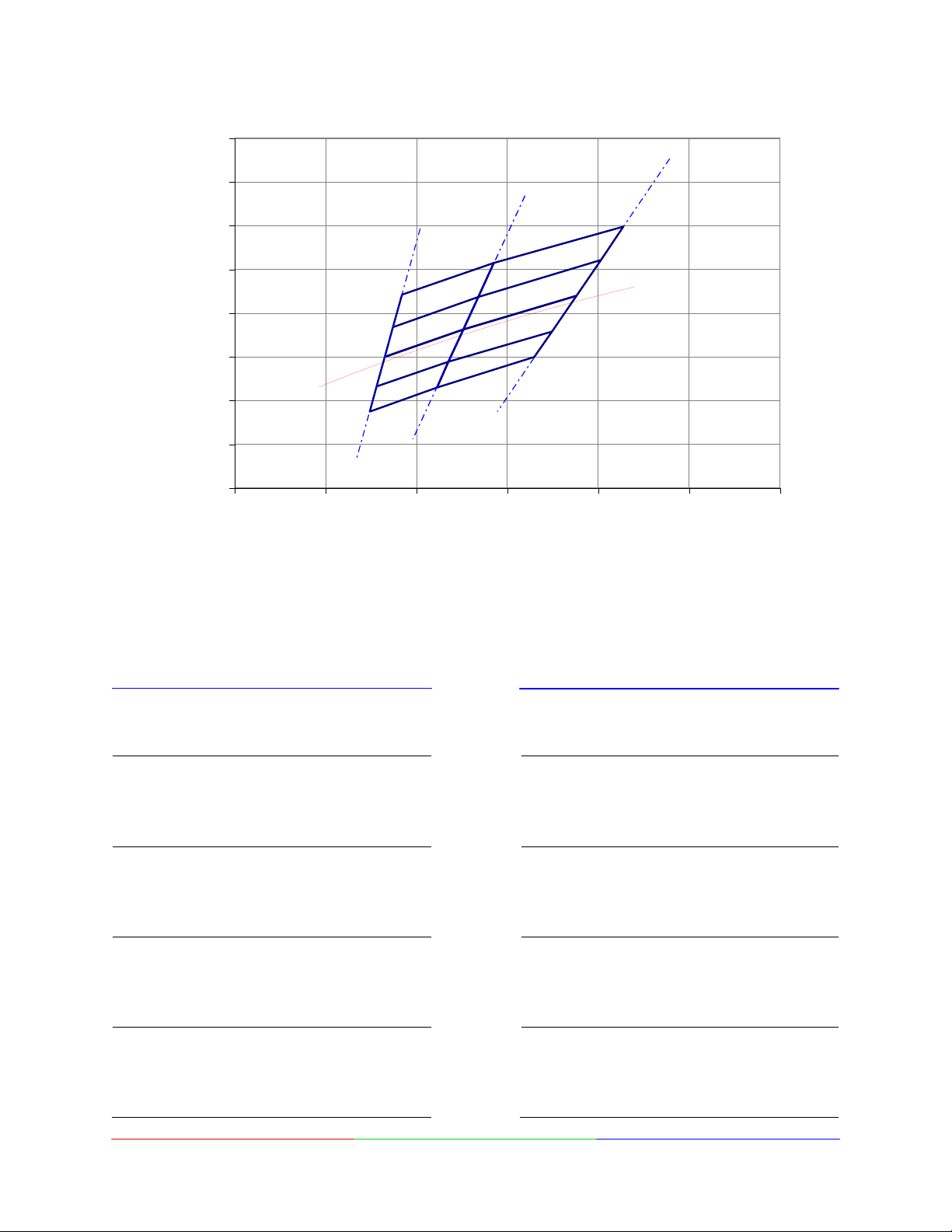
Neutral White Chromaticity Groups
0.46
0.44
0.42
3700 K
4250 K
4750 K
0.40
y
0.38
0.36
0.34
Planckian locus
P2
P3
P4
P5
N5
N2
N3
N4
0.32
0.30
0.32 0.34 0.36 0.38 0.40 0.42 0.44
x
Figure 1: Standard Chromaticity Groups plotted on excerpt from the CIE 1931 (2°) x-y Chromaticity Diagram.
Neutral White Chromaticity Coordinates
Coordinates are listed below in Table 3.
Table 3:
Bin
Code
x y
0.3568
P2
0.3770
0.3736
0.3548
0.3548
P3
0.3736
0.3703
0.3530
0.3530
P4
0.3703
0.3670
0.3512
0.3512
P5
0.3670
0.3645
0.3497
LedEngin, Inc.
0.3885
0.4030
0.3874
0.3736
0.3736
0.3874
0.3726
0.3601
0.3601
0.3726
0.3578
0.3465
0.3465
0.3578
0.3460
0.3350
Typical
CCT
(K)
Bin
Code
4500 N2
4500 N3
4500 N4
4500 N5
4
x y
0.3770
0.4055
0.4006
0.3736
0.3736
0.4006
0.3952
0.3703
0.3703
0.3952
0.3898
0.3670
0.3670
0.3898
0.3859
0.3645
0.4030
0.4196
0.4044
0.3874
0.3874
0.4044
0.3880
0.3726
0.3726
0.3880
0.3716
0.3578
0.3578
0.3716
0.3600
0.3460
LZ1-00NW05 (09/08)
Typical
CCT
(K)
4000
4000
4000
4000
 Loading...