

Page 1
Kansas City: 735 Southwest Blvd Ste B • Kansas City, KS 66103 | 913.912.3760 www.LED-KC.com
Wichita: 327 N Hydraulic Ave, Ste 100 • Wichita, KS 67214 | 316.712.7614 www.LED-Wichita.com
LED Linear Light
8456 in single run (0-10V Dimming)SL
5
Description
Sl8456 linea r light is combin ati on of separated s tru ctures, it is con ven ient to dismant le and maintain b eca use of its
replace abl e power supply an d lig htingemitti ng pa rts(PCB+LED s), s imple shape and r and om jointing can b e rea lized
IP40 wate rpr oof, it is can be wid ely u sed in home, scho ol, shopping mall , hot el and other indo or pu blic placesan d it is
mainly ma de of a luminum alloy, PC.
Applications
Can be widely us ed in home, schoo l, sh opping mall, ho tel a nd other indoor p ubl ic places.
P1
Page 2
Features
Kansas City: 735 Southwest Blvd Ste B • Kansas City, KS 66103 | 913.912.3760 www.LED-KC.com
Wichita: 327 N Hydraulic Ave, Ste 100 • Wichita, KS 67214 | 316.712.7614 www.LED-Wichita.com
1. The pro du ct can op er ate in si ng le
run or c on tinuo us r uns sea ml ess,
when i nput volt ag e is AC277 V, Max
3600 W( 350fe et ) can be co nn ected ;
when i nput volt ag e is 110V, Max
1500 W( 150fe et ) can be co nn ected .
4.PC d if fu sor and AL 60 63 alum in um
prof il e,wit h go od heat d is tribu ti on
and hi gh light effi ci ency.
2.Th e la mp and po we r suppl y is c onnec te d
with h ig h-vol ta ge live p ar t via con ne ctor; i t
is ver y co nveni en t to inst al l and dis as sembl e,
and it i s al so safe a nd r eliab le t o use
5.Th e en d cap, po we r suppl y,e mi tting
part s ca n be disa ss emble d, c onven ie nt
to mai nt ain.
3.La mp b ody ado pt 6 063 alu mi num
prof il e, opti on al whit e, b lack an d
silv er
White grey
6.2 in st allat io n metho ds , suspe nd ent
inst al latio ne c eilin g in stall at ion.
Suspendent
installation
Black
Ceiling
installation
7. Mul ti ple joi nt ing can r ea lized v ia ”十” “L” sha pe c onnec ti ng acce ss ories
Lamp body
SC-S L8 456-0 40 -AW-A0 2- 03CW
SC-S L8 456-0 40 -AW-A0 2- 03NW
SC-S L8 456-0 40 -AW-A0 2- 03WW
SC-S L8 456-0 75 -AW-A0 2- 03CW
SC-S L8 456-0 75 -AW-A0 2- 03NW
5000 K
4000 K
3000 K
5000 K
4000 K
2835
2835
260
260
260
462
462
4320 lm
4280 lm
4120 lm
7875 lm
7725 lm
40W
40W
40W
75W
75W
Length
(feet )
4
4
4
8
8
AC10 0- 277V
50/6 0H z
0-10 V
Dimm in g
5 wire s,
14AWG
copp er
core ,L ,N,G,
DIM+ ,D IM-
SC-S L8 456-0 75 -AW-A0 2- 03WW
3000 K
462
7650 lm
75W
8
P2
Page 3
“L” shape lamp
Kansas City: 735 Southwest Blvd Ste B • Kansas City, KS 66103 | 913.912.3760 www.LED-KC.com
Wichita: 327 N Hydraulic Ave, Ste 100 • Wichita, KS 67214 | 316.712.7614 www.LED-Wichita.com
Length
(feet )
SC-S L8 456T-0 40 -AW-A0 2- 03CW
SC-S L8 456T-0 40 -AW-A0 2- 03NW
SC-S L8 456T-0 40 -AW-A0 2- 03WW
5000 K
4000 K
3000 K
216
216
216
4280 lm
4120 lm
4080 lm
“+” shape lamp
SC-S L8 456R- 04 0-AW-A 02 -03CW
SC-S L8 456R- 04 0-AW-A 02 -03NW
SC-S L8 456R- 04 0-AW-A 02 -03WW
5000 K
4000 K
3000 K
Remark: 3500K an d 4500K is pr ovided fo r optiona l
216
216
216
4400 lm
4320 lm
4240 lm
2* 2
2* 2
2* 2
Length
(feet )
2* 2
2* 2
2* 2
AC100-277V
50/60Hz
AC100-277V
50/60Hz
0-10 V
Dimm in g
0-10 V
Dimm in g
5 wire s,
14AWG
copp er
core ,L ,N,G,
DIM+ ,D IM-
5 wire s,
14AWG
copp er
core ,L ,N,G,
DIM+ ,D IM-
Dimensions(Unit:mm/inch)
84mm /3.30 "
56mm /2.20 "
All di me nsion t ol eranc e is± 1 mm unle ss o therw is e noted .
84mm/3.30"
56mm/2.20"
1203 mm /47.3 6"
2400 mm /94.4 8″
All di me nsion t ol eranc e is± 2 mm unle ss o therw is e noted .
P3
Page 4
Kansas City: 735 Southwest Blvd Ste B • Kansas City, KS 66103 | 913.912.3760 www.LED-KC.com
Wichita: 327 N Hydraulic Ave, Ste 100 • Wichita, KS 67214 | 316.712.7614 www.LED-Wichita.com
717 .50mm
(29 .28″)
84. 00mm
(3. 30″
)
Electrical Connection
717 .50mm
(29 .28″)
(23 .62″)
(29 .28″
717 .50mm
)
(3. 30″)
600 .00mm
84. 00mm
Installation instruction
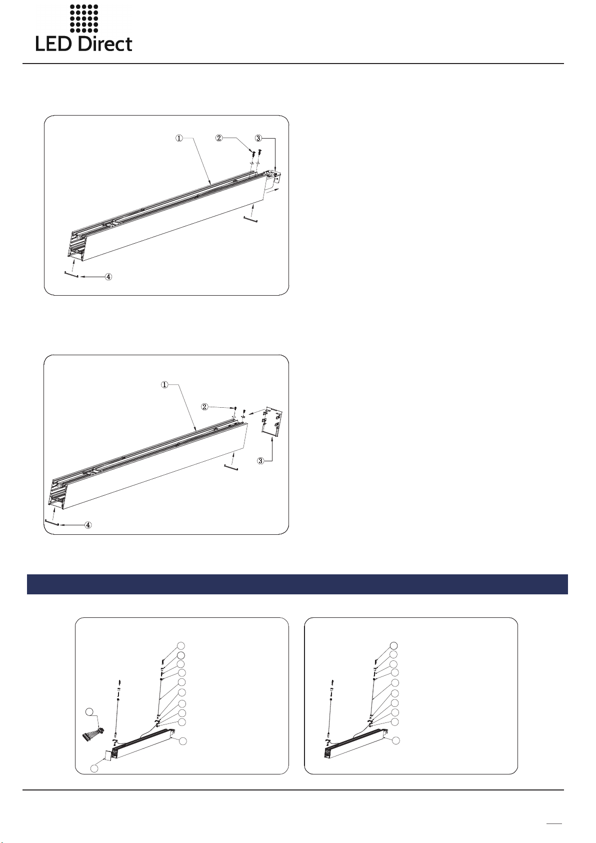
How to make the first run?
1. SL 84 56 l amp b ob y 1pc
2. sc re ws 2pc s
3. in ne r co nne ct or 1pc s
4. in ne r en d cap 2pc s
5. end ca p wi tho ut k no cko ut
(fo r su sp end in g in sta ll at ion )
Or En d ca p wi th kn oc ko ut( fo r ce ili ng i ns tal la ti on)
1pc,t hi s end c ap n ee ds to b e or de red s ep ar ate ly
First ly, loose the 2 screws at the lamp end, and pull
out the i nner conn ector fro m the lamp bo dy, then fi x
the inn er connec tor by 2 scre ws again. Af ter
finis hing the wi ring conn ection( see the ste ps on the
conti nuous con nection ),fix the e nd cap by scr ews
and insert the inn er end caps a t both side s.
1pc
P4
Page 5
Kansas City: 735 Southwest Blvd Ste B • Kansas City, KS 66103 | 913.912.3760 www.LED-KC.com
Wichita: 327 N Hydraulic Ave, Ste 100 • Wichita, KS 67214 | 316.712.7614 www.LED-Wichita.com
How to make the middle run?
1. SL 84 56 l amp b ob y 1p c
2. sc re ws 2pc s
3. in ne r co nne ct or 1pc
4. in ne r en d cap 2pcs
loose t he 2 screws a t the lamp en d, and pull o ut the
inner connecto r from the la mp body, then fix the
inner connecto r by 2 screws a gain, ins ert the inn er
end cap s at both sid es.
How to make the last run?
1. SL 84 56 l amp b od y 1p c
2.scr ew s 2pc s
3.end c ap s 1pc
4.inn er e nd ca ps 2 p cs
Just fi x the end cap a t the last en d by screws ,
and insert the two i nner end ca ps.
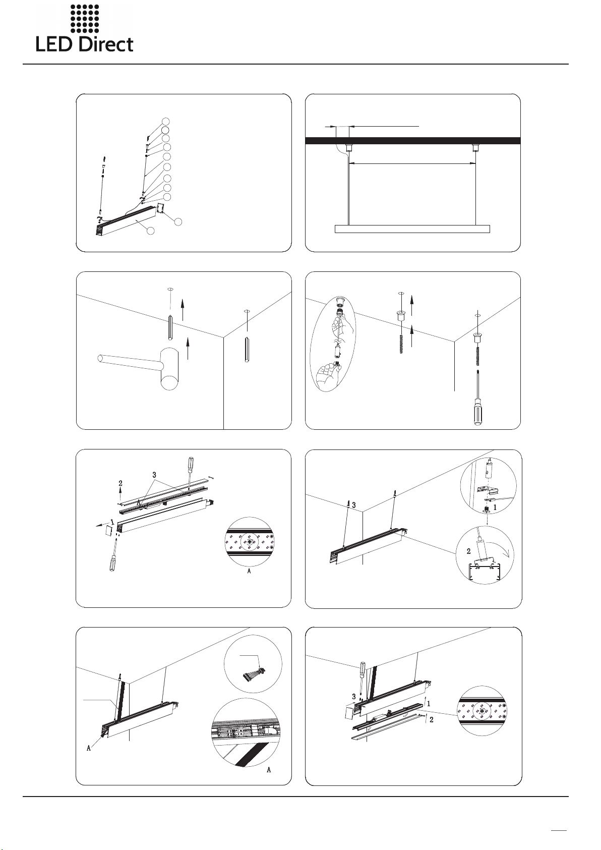
Suspendent Installation Instructions
Exploded drawing of the first run
1111
10
9
8
7
6
12
5
4
3
2
1
Lam p BOM
1.8 456 end c ap 1PC
2. 84 56 lamp 1PC
3. sq uare he ad scre w 2PCS
4. sa fety ro pe 2 PCS
5. cl amp 2PC S
6. wi re lock 2PC S
7. su spend ent rop e 2PCS
8. fi xing he ad1 2P CS
9. 4X 30PA scre w 2PC S
10. f ixing h ead2 2P CS
11. ru bb er pl ug 2PC S
12. i nput wi re 1 PC
Exploded drawing of the middle run
10
Lam p BOM
9
1. 84 56 lamp 1PC
8
2. sq uare he ad scre w 2PCS
7
3. sa fety ro pe 2PC S
6
4. cl amp 2PC S
5
5. wi re lock 2PC S
4
6. su spend ent rop e 2PC S
3
7. fi xing he ad1 2PC S
2
8. 4X 30PA scre w 2PC S
9. fi xing he ad2 2PC S
1
10. r ubber p lug 2PC S
P5
Page 6
Kansas City: 735 Southwest Blvd Ste B • Kansas City, KS 66103 | 913.912.3760 www.LED-KC.com
Wichita: 327 N Hydraulic Ave, Ste 100 • Wichita, KS 67214 | 316.712.7614 www.LED-Wichita.com
Exploded drawing of the end run
11
Lam p BOM
10
1.8 456 end c ap 1 PC
9
2. 84 56 lamp 1P C
8
3. sq uare he ad scre w 2PCS
7
4. sa fety ro pe 2PCS
6
5. cl amp 2PC S
5
6. wi re lock 2PC S
4
7. su spend ent rop e 2PCS
3
8. fi xing he ad1 2PCS
9. 4X 30PA scre w 2PCS
1
2
10. f ixing h ead2 2 PC S
11. ru bb er pl ug 2 PCS
Drill hole
Dri ll hole a ccord ing to co rresp ondin g dimen sion,
and h ammer t he rubb er plug i nto hol e.
Installation diagram
2″(re feren ce dime nsion )
33″(r efere nce dim ensio n)
Disassemble pendant rope and fasten
fixing head of pendent rope
1.C ou nt erc lo ckw ise rot ate and d isman tle
fix ing hea d and squ are scr ew by han d;
2.T hread t he fixi ng head t hroug h penda nt rope , and
fas ten the f ixing h ead of pe ndant r ope in th e plast ic
anc hor wit h screw d river.
Install the first run-disassemble
lamp body
cap w ith scr ewdri ver;a nd pull t he end ca p out wit h hand;
2. Di smant le inne r side co ver and P C cover ;
3. Ro tate tw o screw s of fixi ng card c ounte r-clo ckwis e by 90°, a nd
dis mantl e cooli ng pane l.
1. Lo os e th e scr ew s on th e to p of e nd
Connect the input cabl e
con necto r
condu it
1. Br ea k th rou gh k nocko ut
hol e on spli cing pr ofile ;
2. Fi x the con duit in t he knoc kout ho le;
3. In sert th e femal e conne ctor in to male
con necto r of lamp ;
4. Th re ad AC co nn ec tin g wi re th rough c ondui t, and
res pecti vely co nnect N ,GND, L, DIM+ ,DIM- o f conne ctor.
Install shell of the first run l am p bo dy
1. Th re ad sq ua re -he ad s cre w throu gh fixi ng hole
of sa fey rop e, clam p, then f asten i t with wi re lock ;
2. Sn ap the cl amp int o profi le slot ;
3. Tig hteni ng the la mp with f ixing h ead 1 and f ixing h ead 2.
.
Install the first ru n la mp b od y
1. In stall t he cool ing pan el into s hell of lam p bo dy, an d ro tat e sc rews
of fi xing ca rd cloc kwise b y 90°;
2. Pr ess and m ount th e PC cove r and ins ide cov er plate on l am p;
3. Cl ip the en d cap on th e lamp, and fas ten scr ews on th e top of en d cap.
P6
Page 7
Kansas City: 735 Southwest Blvd Ste B • Kansas City, KS 66103 | 913.912.3760 www.LED-KC.com
Wichita: 327 N Hydraulic Ave, Ste 100 • Wichita, KS 67214 | 316.712.7614 www.LED-Wichita.com
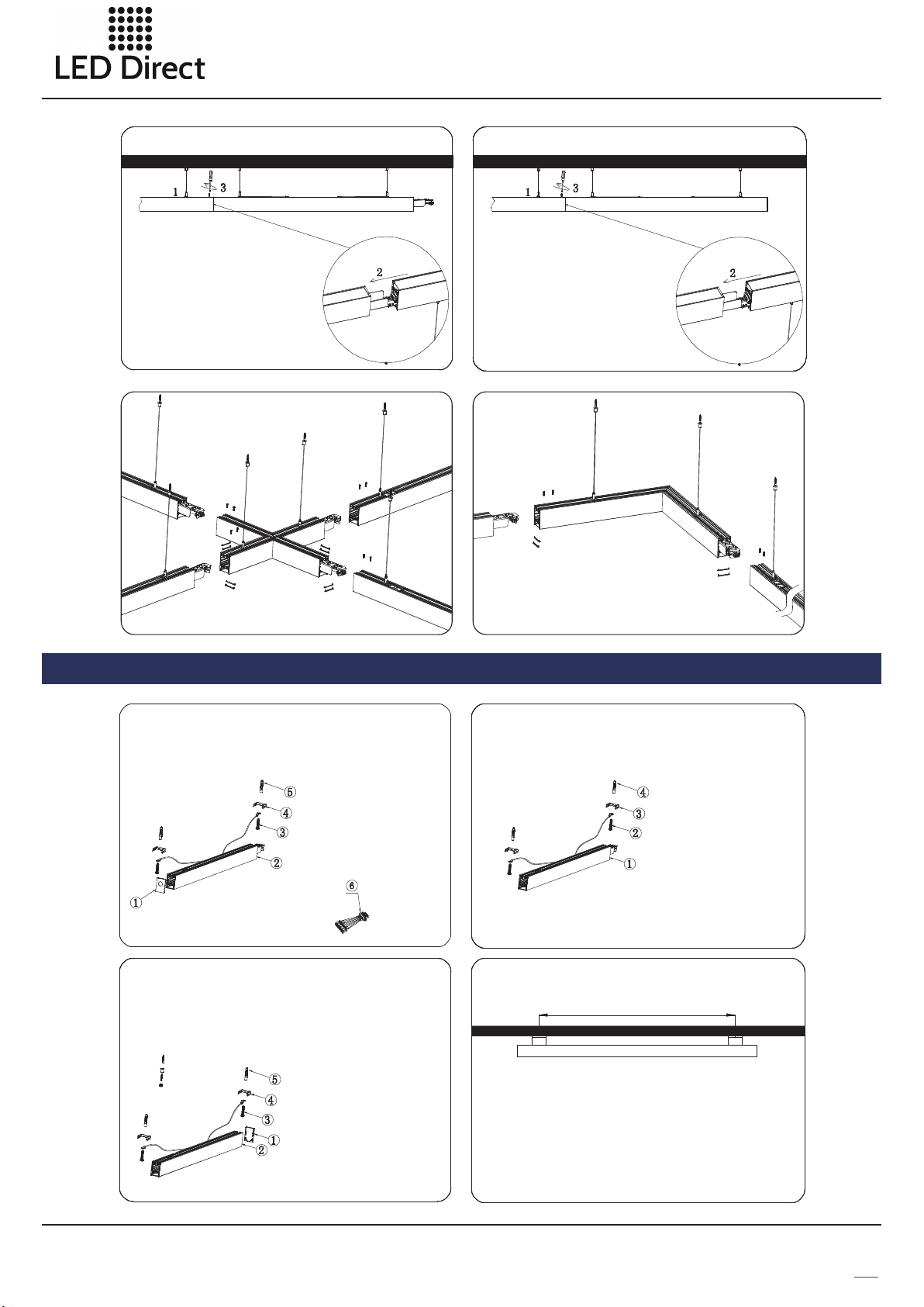
Install lamp bod y of t he m id dl e ru n
1.I nstal l ceili ng lamp i nto pro file sl ot of the
mid dle run l amp;
2.I nsert f emale c onnec tor of th e first m iddle
run i nto the m ale con necto r of the fi rst run ;
and i nsert f emale c onnec tor of th e next
mid dle run i nto mal e conne ctor of pre vi ous
mid dle run ;
3.F asten t he scre ws on joi ning wi th scre wdriver ;
4. Sp licin g quant ity
Whe n input v oltag e is 110V, N*P <15 00W
Whe n input v oltag e is 277V, N *P <3 60 0W
N is to tal run , and P is po we r of si ng le l amp
Install lamp bo dy o f th e en d ru n
1.S nap the c lamp of s uspen dent ro pe into
slo t of lamp p rofil e;
2.I nsert f em al e con ne ct or of e nd r un into
mal e conne ctor of p revio us run;
3. Fa sten th e screw s on j oi nin g wi th
scr ewdri ver.
Ins ta ll ati on d ra win g fo r “+ ”sh ap e la mp
Ins ta ll ati on d ra win g fo r "L “ sha pe l am p
Ceiling Installation Instructions of SL8456
Exploded drawing of the first run
BOM
1. en d cap of in let wir e 1pc
2. 84 56 lamp 1 pc
3. 4* 25PA scre w 2 pcs
4. cl amp 2pc s
5. ru bber pl ug 2pc s
6. in put wir e 1 pc
Exploded drawing of end run
BOM
1. 845 6 end cap 1pc
2. 845 6 lamp 1pc
3. 4*2 5PA scr ew 2p cs
4. cl amp 2 pcs
5. ru bber pl ug 2pcs
Exploded drawing of the mi dd le r un
Installation diagram
BOM
1.8 456 lam p 1pc
2.4 *25PA scr ew 2 pcs
3.c lamp 2p cs
4.r ubber p lug 2pc s
33″(r efere nce dim ensio n)
P7
Page 8
Kansas City: 735 Southwest Blvd Ste B • Kansas City, KS 66103 | 913.912.3760 www.LED-KC.com
Wichita: 327 N Hydraulic Ave, Ste 100 • Wichita, KS 67214 | 316.712.7614 www.LED-Wichita.com
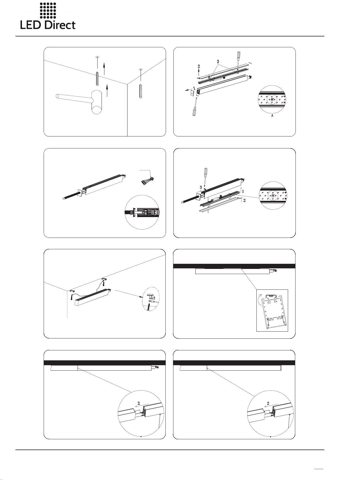
Drill hole
Dri ll hole a ccord ing to co rresp ondin g dimen sion,
and h ammer t he rubb er plug i nto hol e
Connect the input cable
1. Br eak thr ough kn ockou t hole on s plici ng prof ile;
2. Fi x the con duit in t he knoc kout ho le;
3. In sert th e femal e conne ctor in to male
con necto r of lamp ;
4. Th re ad AC co nn ectin g wi re th ro ug h con du it,
and r espec tivel y conne ct N,GN D,L, DI M+,DI M- of
con necto r.nsio n, and ha mmer th e rubbe r plug into h ol e
con necto r
Installation of the first run-disassemble lamp body
1. Un sc re w the s cr ews o n th e si de of
end c ap w it h scr ew dri ve r; pul l th e end
2. Di smant le inne r side co ver and P C cover ;
3. Ro tate tw o screw s of fixi ng card c ounte r-clo ckwis e by 90°, a nd
dis mantl e cooli ng pane l.
cap o ut b y ha nd;
Install the first run lamp body
1. In stall t he cool ing pan el into s hell of l amp bod y, and r otate s crews of
fix ing car d clock wise by 9 0° to fas ten the c oolin g panel i nto the l amp;
2. Pr ess and m ount th e PC cove r and ins ide cov er plat e on lamp ;
3. Cl ip the en d cap on th e lamp, and fas ten scr ews on th e top of en d cap.
Install the clamp of the first run lamp b od y
Thr ead the s crew th rough f ixing h oles of s afety r ope and c lamp, a nd
fas ten the s crew wi th rubb er plug i n the cei ling
Install lamp body of the middle run
1.I nstal l ceili ng lamp i nto pro file sl ot of the
mid dle run l amp;
2.I nsert f emale c onnec tor of th e first m iddle r un
int o the mal e conne ctor of t he firs t run ; and
ins ert fem ale con necto r of the ne xt midd le run
int o male co nnect or of pre vious m iddle r un.
3. Sp licin g quant ity
Whe n input v oltag e is 110V, N*P < 80 0W
Whe n input v oltag e is 277V, N *P <2 270W
N is to tal run , and P is po we r of si ng le la mp
Install the first run lamp body
Acc ordin g to the fi gure, i nstal l the cla mp on one
sid e, then r otate a nd pres s mount ing to an other
sid e of the cl amp;
Install lampbody of the end run
1.S nap the c lamp of s uspen dent ro pe into
slo t of lamp p rofil e;
2.I nsert f emale c onnec tor of en d run int o
mal e conne ctor of p revio us run.
P8
Page 9
Kansas City: 735 Southwest Blvd Ste B • Kansas City, KS 66103 | 913.912.3760 www.LED-KC.com
Wichita: 327 N Hydraulic Ave, Ste 100 • Wichita, KS 67214 | 316.712.7614 www.LED-Wichita.com
Product packaging information:
1.2m lamp: 2.4m lamp:
net wei ght/pc: 3.24kg
gross w eight/C TN:24.8 kg
inner s ize: 1274 *130*10 6mm
carto n size: 128 8*404*2 30mm
1pcs/inner box,6 inner boxes/ carton
“L” lamp “+” lamp:
net wei ght/pc: 3.294kg
gross w eight/C TN:16.6 31kg
inner s ize: 735* 105*683 mm
carto n size: 750 *225*70 1mm
2pcs/inner box,2 inner boxes/ carton
Notice
net wei ght/pc: 6.5kg
gross w eight/C TN:33kg
inner s ize: 2448 *133*10 6mm
carto n size: 246 2*413*2 30mm
1pcs/inner box,4 inner boxes/ carton
net wei ght/pc: 3.667kg
gross w eight/C TN:9.81 8kg
inner s ize: mm
632*105*566
carto n size: 647 *225*58 4mm
1pcs/inner box,2 inner boxes/ carton
1. Please r ead t he specificat ion f irst, to make sur e the s ervice enviro nme nt matches t he co ndition in the
specifi cat ion before usin g.
2. Please c onf irm the input vol tag e, frequency be for e using.
3.The lam p mus t be installed by p rof essional pers onn el
4. If there i s any d amage on the powe r lin e or the shell of the p rod uct, it should be t ake n as defecti ve pr oduct and do
not use it. ;
5. Danger ous h igh voltage, No n-p rofessional s are n ot allowed to mai nta in the products .
6. If the ext eri or flexible cab le or w ire is damaged, i t mus t be exchanged by t he su pplier, its a gen t or other simila r
qualifi ed pe rsonnel to avoi d dan gers.
P9
 Loading...