

Page 1
LedControlCard.com Focus On led card and led video processor
LVP603S
LED Video Processor
USER’S MANUAL
www.ledcontrolcard.com led control website.
Page 2

LVP603S User’s Manual
---------------------------------------------------------------------------------------------------
LED VIDEO PROCESSOR
2
TABLE OF CONTENTS
I. Safety precautions 3
II. Connections of hardware
1. Rear view 4
2. Port description 4
3. Connection diagram 5
III. Frontal panel operations
1. Diagram of frontal panel 6
2. Button instructions (operation mode) 6
IV. Setup
1. Enter setup of LVP603S 11
2. Select language 11
3. Output image setup 12
4. Brightness / color / definition 13
5. PIP / POP output image setup 14
6. Text Overlay setup 16
7. Input image setup 17
8. Audio configurations 20
9. Exit setup 20
10. Factory district setup 21
V. Specifications 22
VI.Notes to model…………………………………………………………….23
Page 3

LVP603S User’s Manual
---------------------------------------------------------------------------------------------------
LED VIDEO PROCESSOR
3
I. Safety Precautions
Danger!
There is high voltage in the processor, to prevent any unexpected
hazard, unless you are maintenance, please do not open the cover of the
device.
Warning!
1. This device shall not encounter water sprinkle or splash, please do not
place anything containing water on this device.
2. To prevent fire, keep this device far from any fire source.
3. If this device gives out any strange noise, smoke or smell, please
immediately unplug the power cord from receptacle, and contact local
dealer.
4. Please do not plug or unplug DVI signal cable when the device
on power.
Caution!
1. Please thoroughly read this manual before using this device, and keep
it well for future reference.
2. In the event of lighting or when you are not going to use the device for
a long time, please pull the power plug out of receptacle.
3. Nobody other than professional technicians can operate the device,
unless they have been appropriately trained or under guidance of
technicians.
4. To prevent equipment damage or electric shock, please don’t fill in
anything in the vent of the device.
5. Do not place the device near any water source or anywhere damp.
6. Do not place the device near any radiator or anywhere under high
temperature.
7. To prevent rupture or damage of power cords, please handle and keep
them properly.
8. Please immediately unplug power cord and have the device repaired,
when
1) Liquid splashes to the device.
2) The device is dropped down or cabinet is damaged.
3) Obvious malpractice is found or performance degrades.
Page 4
LVP603S User’s Manual
II. Connections of hardware
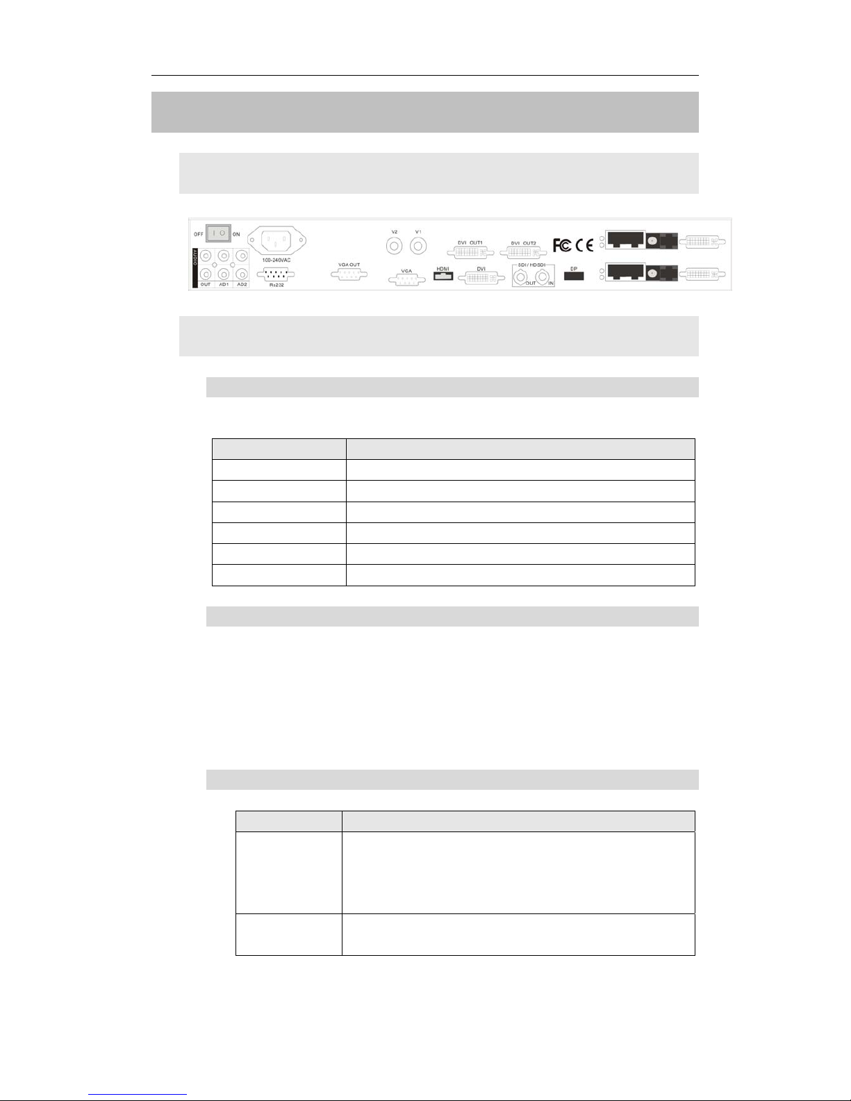
1. Rear view
Figure 1
2. Port description
1) Video Input
LVP603S supports 7-channel signal input, including:
Port name Description
V1~V2
2-channel PAL/NTSC composite video input
VGA
1-channel computer analog signal input
DP(DisplayPort)
1-channel DisplayPort digital hd signal input
DVI
1-channel computer digital signal input
HDMI
1-channel HDMI digital HD signal input
SDI/HDSDI (IN)
1-channel digital video signal input ( SD/HD)
2) Audio Input
LVP603S supports 5-channel stereo audio switch. Of which, 3
channels are DP, HDMI and SDI audios, the other 2 channels are
AD1, AD2 external input audio. AD1 and AD2 can be mapped to
the any one of all video inputs, and will be switched synchronous to
the selection of video input signals.
3) Video Output
Port name Description
VGA OUT
1-channel analog RGBHV signal output, it can be
connected to a local display device and used as
monitor (it is strongly recommended to use this
port when operating and setting LVP603S).
DVI OUT 1 /
DVI OUT 2
2 same DVI digital graphic signal output, it can
be connected with external LED transmission
---------------------------------------------------------------------------------------------------
LED VIDEO PROCESSOR
4
Page 5
LVP603S User’s Manual
card or LED transmission box
SDI/HD SDI
(0UT)
1-channel digital video signal loop output
4) Audio Output (AUDIO OUT)
Corresponds to the selected video input signal, output this
channel audio input signals.
5) Signals of other ports
RS232 serial communication port
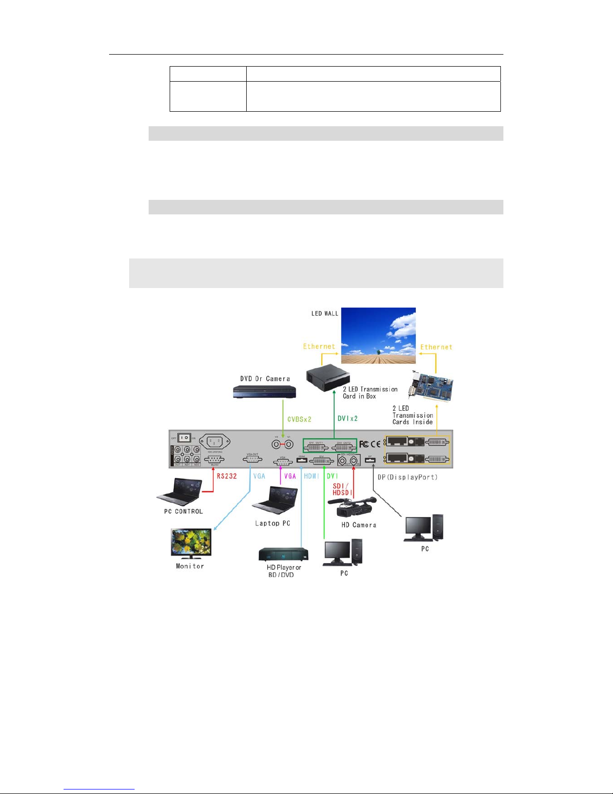
3. Connection diagram
---------------------------------------------------------------------------------------------------
LED VIDEO PROCESSOR
5
Page 6
LVP603S User’s Manual
III. Frontal panel operations
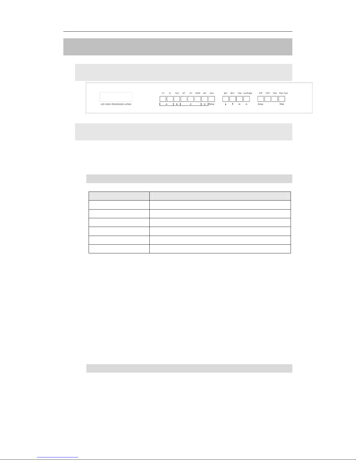
1. Diagram of frontal panel
Figure 2
2. Button instructions (operation mode):
There are 16 buttons on the frontal panel of LVP603S, all these
buttons will be operable after start. they have the following functions as
described below:
1) Select input video source
Port name Description
V1~V2
2-channel PAL/NTSC composite video input
VGA
1-channel computer analog signal input
DP(Display Port)
1-channel DisplayPort digital HD signal input
DVI
1-channel computer digital signal input
HDMI
1-channel HDMI digital HD signal input
SDI/HDSDI (IN)
1-channel digital video signal input ( SD/HD)
Switch audio input while operating above buttons; select the audio
signal input from corresponding video input to output it through Audio
OUT.
Notes: when user has selected input signal, the current input
signal source that you selected, e.g.: INPUT=HDMI will appear in the
LCD. In the meantime, the indicator above the corresponding button
will indicate the status of current input signal source. If there is no valid
signal input, the indicator will blink and dark screen appears; if the
signal is valid, the indicator will illuminate.
2) VGA input auto adjustment (Auto)
---------------------------------------------------------------------------------------------------
LED VIDEO PROCESSOR
6
When the current VGA input source of LVP603S is a valid
signal, press this button, LVP603S will automatically adjust the
sampling parameters of the VGA signals, so as to make VGA
Page 7
LVP603S User’s Manual
---------------------------------------------------------------------------------------------------
LED VIDEO PROCESSOR
7
picture clean and complete.
In general, this operation is made only when new VGA signal
source is to be connected in. Sometimes user need repetitively do
such adjustment till VGA picture looks clean, complete and stable.
3) Select output brightness
Button names Description
BRT -
Decrease output image brightness of
LVP603S, the lowest brightness is 0.
BRT + Increase output image brightness of LVP603S,
the highest brightness is 64.
LVP603S supports 32 levels Brightness, “0” represents the
lowest brightness, and 64 represents the highest brightness. To
ensure full gray level of output image, normally the output
brightness is set as 64!
4) Information display (Info)
This button can be operated to display the following two status
information:
Current settings of LVP603S: press “Info” button to display
current settings and information of LVP603S. There are total 29
items of information. Press “Info” button again before the
information disappears in LCD, the next entry of information will
appear in LCD.
Status of current input signal source: press current input
selection button, then press “Info” immediately, the input signal
source selected, e.g.: “In: HDMI”, will appear in line 1 in LCD, and
the status of current input signal source will appear in line 2 in LCD.
If no valid signal is input, “No Input” will appear in LCD; if the signal
is valid, its input signal format such as “1080p_60Hz” will appear in
LCD.
5) Select Cut / Fide mode
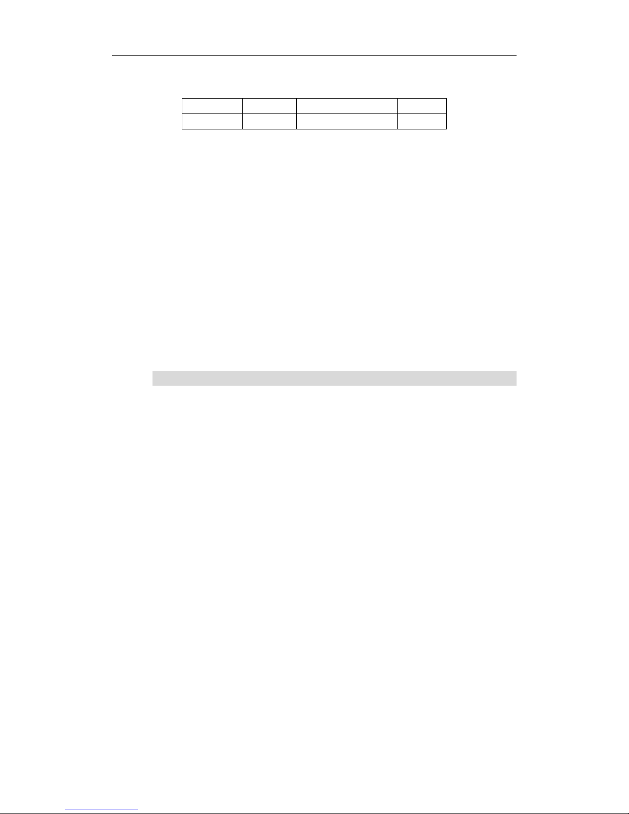
LVP603S can realize seamless or fading in/out switching
effects, i.e.: Cut, Fide, between the signals coming from the
following 4 groups. But if the signals come from the same group,
LVP603S can only realize freezing seamless switching effect.
Page 8
LVP603S User’s Manual
---------------------------------------------------------------------------------------------------
LED VIDEO PROCESSOR
8
A B C D
V1,V2
VGA
DP,DVI,HDMI
SDI
Cut: the moment the LED indicator above the button is off. In
this mode, user can transiently shift picture seamlessly without
flickering, tremble, stasis, delay, black screen occurring. Cut is the
default special effect switching mode of LVP603S.
Fide (Fading-in/out mode): the moment the LED indicator
above the button is on. In this mode, user can shift the picture
coming from different input signal groups in fading-in/out mode
without flickering, tremble, stasis, delay, black screen occurring.
Freezing seamless switching: the pictures coming from the
same group can only be shifted in freezing seamless switching
mode. That is to say, after you select another input signal which
belongs to the same group with that of currently displayed signal,
current signal will first be frozen, then be superseded transiently by
the signal you selected.
6) PIP / POP
PIP mode of LVP603S allows user to insert a PIP window in
current picture, and the size and location of the PIP window can be
changed freely. The signals to be displayed in PIP window can
either be signals coming from other groups or be current signal
itself. Here we define current picture as background, and the
picture to be added as PIP.
Operating procedures:
Enter PIP display mode: Press PIP button, the indicator
above the button is on, LVP603S will enter PIP mode, in the
meantime, the corresponding input signal codes of background and
PIP will appear in LCD, e.g.: “background=V1, PIP=DVI”.
Change PIP: while in PIP mode, press buttons to select
another input signal coming from other groups or current signal
itself, this picture will be set as PIP.
Change the background: you must first press PIP button to
disable PIP mode. Select appropriate input signal as background,
then press PIP button to switch to PIP mode, then select a new PIP
picture.
Enter POP mode: press POP button while in PIP mode, the
indicator above the button is ON, and LVP603S will enter POP
mode. The moment the LED is divided into two sectors respectively
Page 9
LVP603S User’s Manual
---------------------------------------------------------------------------------------------------
LED VIDEO PROCESSOR
9
on the left and on the right, which display the input signals of
background and PIP respectively. The information “Left=V1, Right
=DVI” appears in LCD. User can shift PIP and POP modes by
pressing POP button.
7) Text Overlay mode(Text)
LVP603S can add caption, company logo or animation onto
current picture, while current picture is normally displayed, press
Text button to go to caption adding mode, then select the signal
source of caption. The captions can be made by office software
such as Powerpoint.
8) Part / Full
Press this button to switch between Part / Full display mode.
While in non-multi-screen mode, this operation is only to switch
over when the input signal is PC (VGA / DP / DVI / HDMI), and
other signals can work only in the Full display mode.
Mode Description
Full
Full screen display. LED displays entire input picture, the
moment the indicator above the button is OFF.
Part
Part screen display. LED only displays a part of input
picture, the moment the indicator above the button is ON.
While multi-screen display mode, press this button, the picture
will change in part or full screen mode.
Caution: In part screen display mode. please don’t activate
PIP/POP function, otherwise, the LED will be unable to display the
picture completely.
Page 10
LVP603S User’s Manual
---------------------------------------------------------------------------------------------------
LED VIDEO PROCESSOR
10
IV. Setup
The following setup must be made by relevant qualified
technicians. For ordinary users, unless they have received adequate
relevant training, they shall not attempt the following setup
operations!
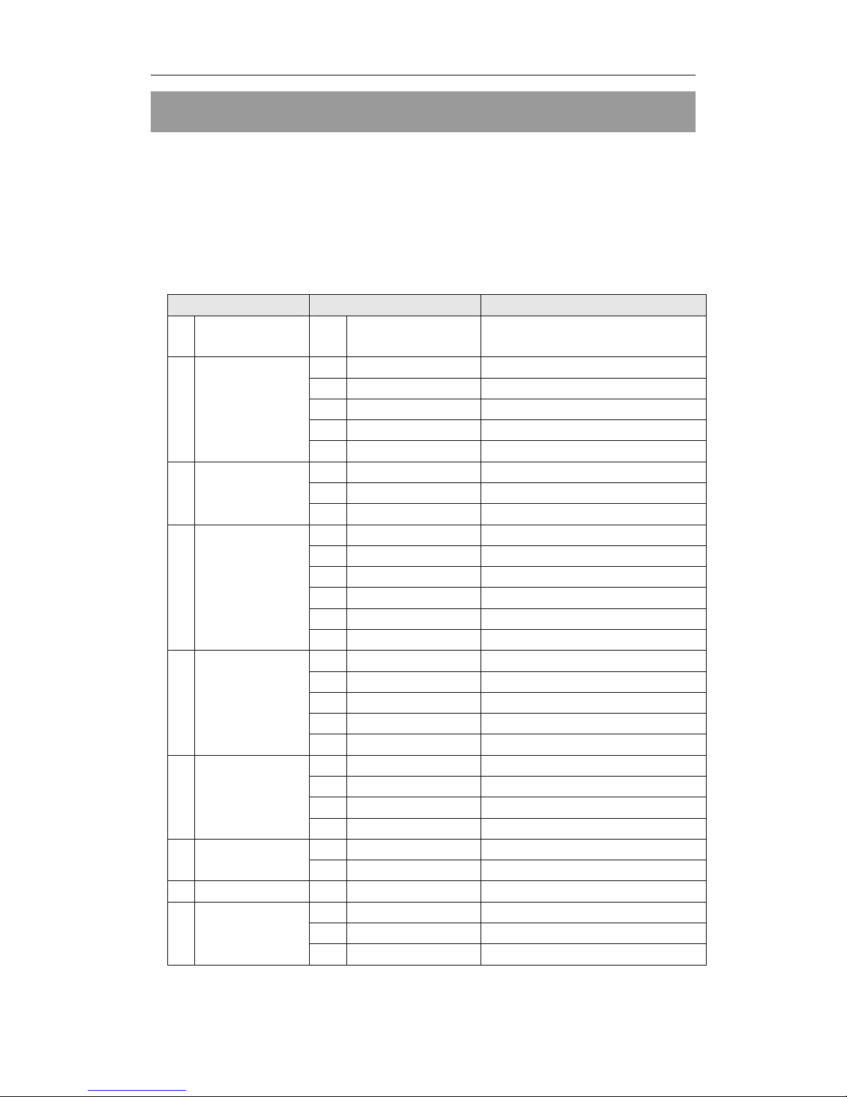
There are 29 items in 6 categories available for you to set in LVP603S.
Technicians can set these items as necessary, for details see the table
below:
Category Items Description
1 Language
Selection
1 Language
语言
2
Hori_Start
Output horizontal start
3
Hori_Width
Output width
4
Vert_Start
Output vertical start
5
Vert_Height
Output height
2 Output Image
Setup
6
Out Format
Output resolution
7
Brightness
8
Color
3 Brightness /
Color
20
Definition
9
PIP_ H_Start
PIP Output horizontal start
10
PIP_H_Width
PIP Output width
11
PIP_V_Start
PIP Output vertical start
12
PIP_V_Heigh
PIP Output height
13
PIP_Frame
4 PIP/POP
Output Image
Setup
14
POP _Height
15
Text_Mode
16
Text_Thd_RGB
17
Text_Thd_R
18
Text_Thd_G
5 Text Overlay
Setup
19
Text_Thd_B
21
Input_Width
Width of input image
22
Input_Height
Height of input image
23
Hori_In_Str
Input horizontal start
6 Input Image
Setup
24
Vert_In_Str
Input vertical start
25
Audio1 Confi
Audio1 configurations 7 Audio
Configurations
26
Audio2 Confi
Audio2 configurations
27
Exit Setup
16
Device_Init
17
Bias
8 Factory
district Setup
18
Auto ADC
Page 11
LVP603S User’s Manual
---------------------------------------------------------------------------------------------------
LED VIDEO PROCESSOR
11
1. Enter Setup of LVP603S
Press “Setup” for consecutive 8 times while in operation mode,
“Password: 8 Enter Setup …” will appear in LCD, LVP6 03S will enter
the No.1 setup item.
After LVP603S enters the setup mode, the 7 buttons on frontal
panel will have the functions as defined in table below:
Name Functions
Step
Select step value 1 or 10
↑ Move to next item
↓ Move to last item
← Decrease value or select last value
→ Increase value or select next value
Enter
Save the adjustment or selected values
Setting
Enter or exit setting mode
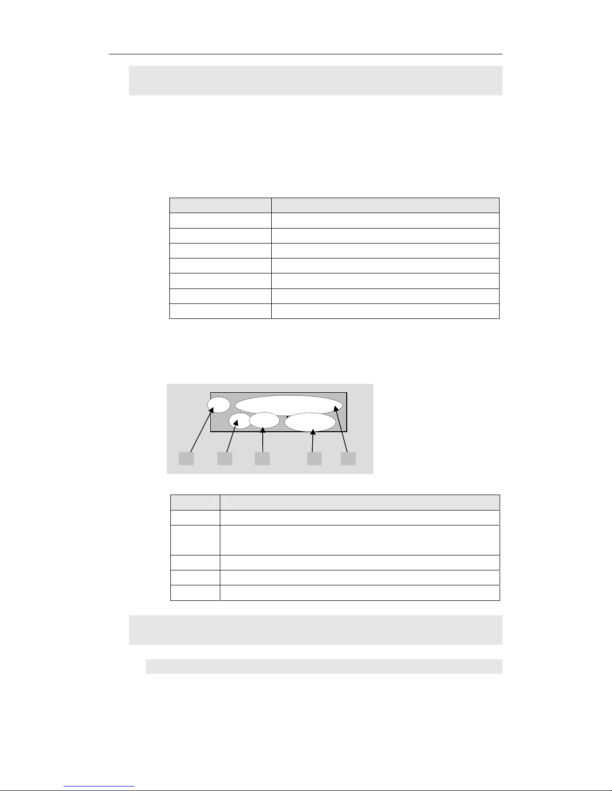
After LVP603S enters setting mode, the relevant setting
information will be displayed in LCD as per the layout shown in the
figure below:
Figure 3
As shown in above figure, LCD consists of five sectors:
Sector Description
1 The No. of current setting item
2 ?: ask you whether to save the adjustment; !: The
adjustment already be saved and takes effect.
3 Newly adjusted value
4 Step value
5 Name of current setting item
2. Select language
Item 1: “Language
语言
”
2 : Hori_Start
?200 Stp=10
1 2 3 54
Page 12
LVP603S User’s Manual
---------------------------------------------------------------------------------------------------
LED VIDEO PROCESSOR
12
After entering setting mode, LVP603S will enter the first setting
item “Language
语言
”. LVP603S supports Chinese and English
display, press “←” or “→” to select either of them, then press
“Enter” to save it and make it valid.
3. Output image setup
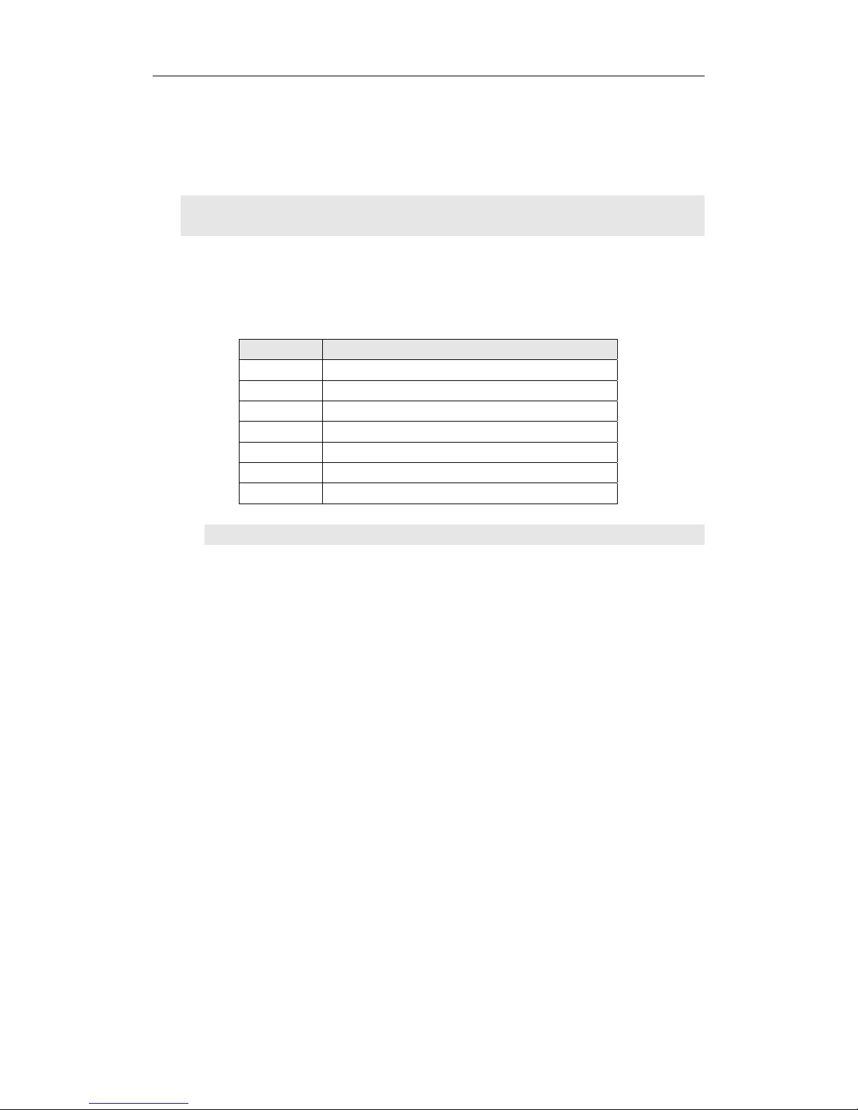
LVP603S outputs images from VGA OUT, DVI OUT1 and DVI OUT2.
There are 7 output formats as listed in the table below. User can enter the
No.6 setting item “Out Format” to select one of them.
Format
1 1024×768_60
2 1024×768_75
3 1280×1024_60
4 1280×1024_75
5 1600×1200_60
6 1920×1080_50
7 1920×1080_60
Item 6: “Out_Format”
Press “←” or “→” key to select 1 output format listed under this
option, then press “Enter” to save it.
If you select “1024×768_60”, the output resolution of LVP603S will
be 1024×768; the vertical refresh rate is 60Hz.
However, the resolution of LED screen is not exactly 1024×768
pixels. When the resolution of LED screen is less than 1024×768
pixels, we can set LVP603S to output the images exactly fitting the
resolution of LED screen, so that the LED could display a full frame of
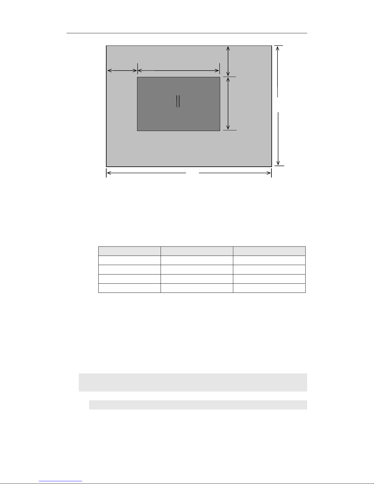
image. See the schematic diagram below:
Page 13
LVP603S User’s Manual
---------------------------------------------------------------------------------------------------
LED VIDEO PROCESSOR
13
Figure 4
As above figure shows: the size and location of LVP603S output
images are defined by 4 groups of parameters, which correspond to
four setting items respectively, for details of their relationship see Table
5 below:
No. of setup item Setup Item Name Names of parameters
2
Hori_Start
Hor_Str
3
Hori_Width
Hor_Width
4
Vert_Start
Vert_Str
5 Vert_Height
Vert_Height
The start coordinates (0, 0) of LVP603S output image is defined in
the left top of 1024×768 pixels output area.
Set the four setup items as listed in above table as per the size of
current LED screen (pixels) and start position of the input image that
LED displays. Press “↑” or “↓” to select setup item, press “←” or “→”
to increase or decrease the values of current item. Press “Enter” to
save the settings.
4. Brightness / Color / Definition
Item 7: “Brightness”
LVP603S supports 32 levels Brightness, “0” represents the lowest
(0,0)
Hor_Str Hor_Width
Vert_Str
Vert_Height
LED Dispaly Screen
LVP603S Out Format =
1024×768
LVP603S Out Image Area
1024
768
Page 14
LVP603S User’s Manual
brightness, and 64 represents the highest brightness.
Press “←” or “→” to increase or decrease the values of brightness.
Press “Enter” to save the settings.
To ensure full gray level of output image, normally the output
brightness is set as 64!
Item 8: “Color”
For V1, V2, DP and HDMI video input source, LVP603S can set
color saturation for them ranging from 22 to 38. The lower this value is,
the weaker the color looks; the higher this value is, the stronger the
color looks. Press “←” or “→” to increase or decrease the values of
color saturation. Press “Enter” to save the settings.
Normally the value of color saturation is set as 30!
Item 20: “Definition”
LVP603S provides “sharp” or “normal” as options of definition. In
sharp mode, the picture edge looks clearly, and image has higher
definition; while in “normal” mode, the picture looks milder. Normally
the value of Definition saturation is set as “normal”!
5. PIP/POP Output Image Setup
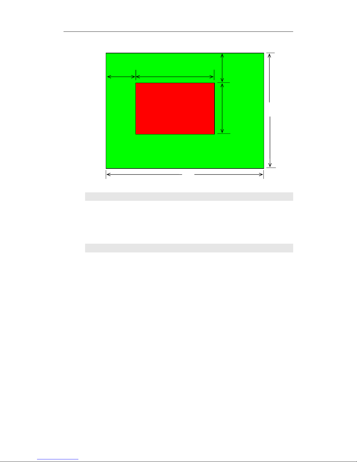
Items 9~12: “PIP image output setup”
LVP603S PIP image window is located in LED screen. As in PIP
mode the PIP image is to be zoomed-in/out after being added to
background, it means that 4 values listed in items 9~12 in the table
below don’t represent their pixels in LED, but represent the width and
height value of output resolution “Out_Format” in the 6
th
option of
setting menu. For details see figure below (provided “Out_Format”
adopts 1920×1080 mode).
9
PIP_ H_Start PIP horizontal start
10
PIP_H_Width PIP width
11
PIP_V_Start PIP vertical start
12
PIP_V_Heigh PIP height
Note: the minimum values of PIP_H_Width and PIP_V_Heigh are
both 128.
---------------------------------------------------------------------------------------------------
LED VIDEO PROCESSOR
14
Page 15
LVP603S User’s Manual
---------------------------------------------------------------------------------------------------
LED VIDEO PROCESSOR
15
(0,0)
H_Start_PIP
H_Width_PIP
V_Start_PIP
V_Heigh_PIP
LVP603S Out Format =
1920×1080
1920
1080
PIP W indow
Item 13: ” PIP_Frame”
User can set frame mode in PIP image window of LVP603S. There
are 4 setting options, i.e.: “No frame”, “black 2 line”, “white 2 line” and
“blue 2 line”.
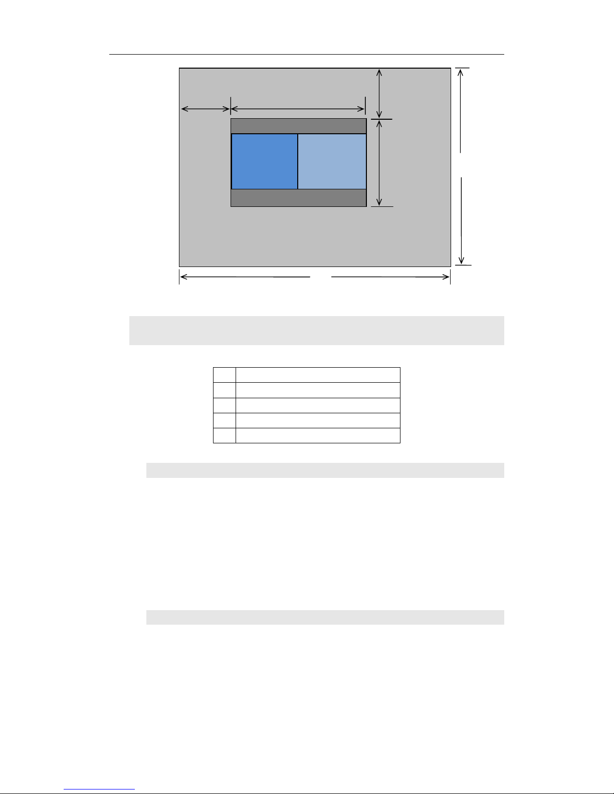
Item 14: ”POP_Height”
LVP603S allows users to set POP image height by themselves.
Like items 9~12, this value doesn’t represent the actual LED pixels. Its
minimum value is 128. When this value is less than the maximum
value, the image will be located in the centre of display as the figure
below shows:
Page 16
LVP603S User’s Manual
768
Left Image
LED Dispaly Screen
LVP603S Out Image Area
Right Image
Vert_Str
Vert_Height
Hor_Str Hor_Width
(0,0)
1024
6. Text Overlay Setup
---------------------------------------------------------------------------------------------------
LED VIDEO PROCESSOR
16
15
Text Mode
16
Text_Thd_RGB
17
Text_Thd_R
18
Text_Thd_G
19
Text_Thd_B
Item 15: “Text Mode”
LVP603S allows user to set caption knock-out “< threshold” or
“>threshold”. If it is less than threshold value, it means that the
image of caption signal less than current color threshold value will be
added to background, while the part greater than threshold will be
automatically filtered. If it is greater than threshold value, it means
that the image of caption signal greater than current color threshold
value will be added to background.
Item 16: ” Text_Thd_RGB”
LVP603S users can set R, G, B values of caption threshold value
by themselves, the three values can be set to be the same within
0~252.
Page 17
LVP603S User’s Manual
Item 17~19: ” Text_Thd_R/G/B”
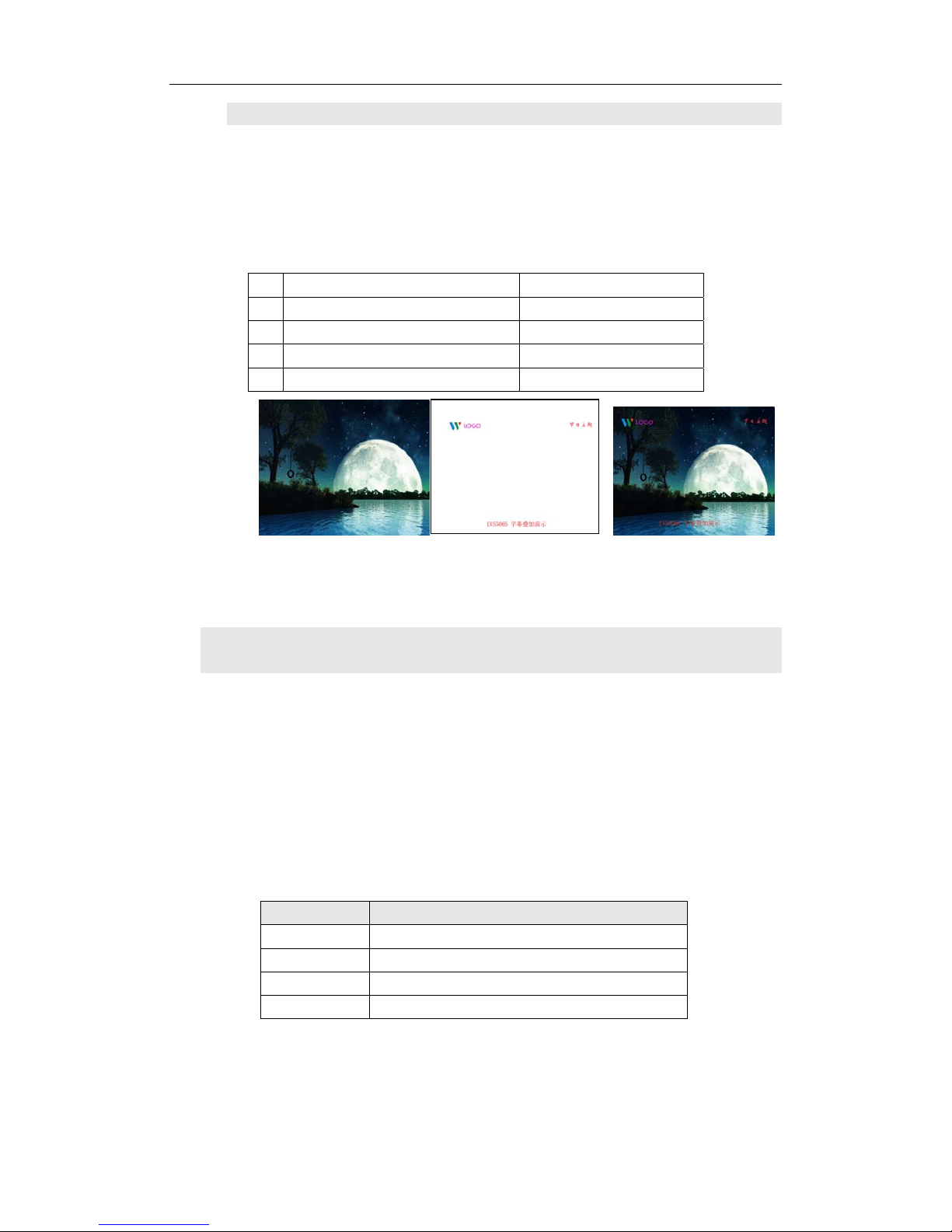
The three options are used to set R, G, B values respectively as a
certain value within 0~252.
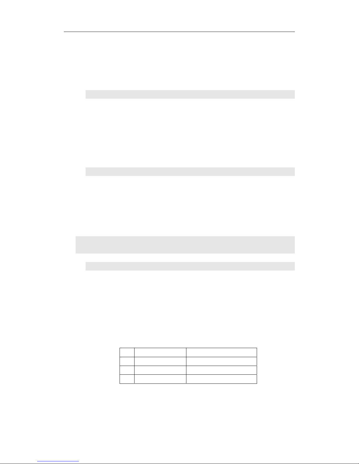
The following figure shows an example of caption adding function.
The caption document in this sample is made using Powerpoint. Its
parameters are set as below:
15
Caption knock-out mode <Threshold
16
Caption threshold RGB 232
17
Caption threshold R Default
18
Caption threshold G Default
19
Caption threshold B Default
Background Text Text Overlay
7. Input image setup
LVP603S supports multiple machines to work together in parallel,
in such mode, a number of small LED screen make up a large screen.
If the output format of LVP603S is: 1920×1080, when 2 sets of
LVP603S are connected in parallel, they can connect any LED screen
of no higher than 3840×1080 pixels.
When a number of LVP603S are connected in parallel in
applications, user should set input image parameters of each
LVP603S. For details of parameters see the table below:
Items No. Item Name
21
Input_width
22
Input_height
23
Hori_In_Str
24
Vert_In_Str
---------------------------------------------------------------------------------------------------
LED VIDEO PROCESSOR
17
Caution: When work together in parallel, each set of LVP603S
should retain the same data in set-up of brightness, bias and Definition
Page 18
LVP603S User’s Manual
as a result to keep the image compatibility.
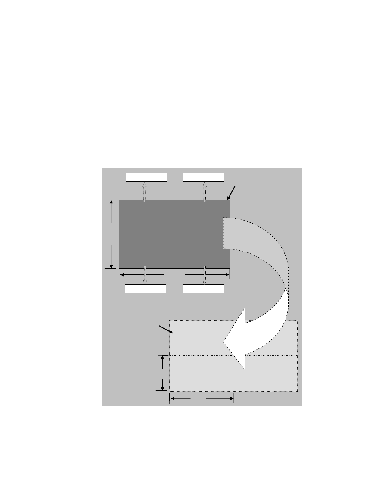
Figure below shows the example of a 2×2 sets of LVP603S
connected in parallel, in which 4 small LEDs make up a large screen.
Provided the resolution of each small LED is 1728×960, the output
image of each set of LVP603S will first be set as below:
Out Format = 1920×1080
Hori_Width = 1728
Vert_Height = 960
Then we should set the input images of each set of LVP603S. As
shown in figure below, to show a complete large picture, each set of
LVP603S shall capture the corresponding part of input images.
1080
1920
(0,0)
(960,0)
(0,540) (960,540)
1# LVP603S 2# LVP603S
3# LVP603S 4# LVP603S
Input image
1728
960
LED screen
Figure 5
---------------------------------------------------------------------------------------------------
LED VIDEO PROCESSOR
18
Page 19

LVP603S User’s Manual
---------------------------------------------------------------------------------------------------
LED VIDEO PROCESSOR
19
Item 21: “Input_Width”
This item has four values for your choice, i.e.: 100%, 1/2,1/3 and
1/4. 100% means that 100% images in horizontal direction are input;
1/N (N=2, 3, 4) means only 1/N images are input. If 3 sets of LVP603S
are connected in parallel in horizontal direction, each set of LVP603S
will capture 1/3 of input image. Press “←” or “→” key to select width of
input image, then press “Enter” to save the settings.
As shown in Figure 5, the width of input image for the 4 sets of
LVP603S should be set as:
Input_Width = 1 / 2
Item 22: “Input_Height”
This item has four values for your choice, i.e.: 100%, 1/2, 1/3 and
9/16. 100% means that 100% images in vertical direction are input;
1/N(N=2,3) means only 1/N image are input. If 3 sets of LVP603S are
connected in parallel in horizontal direction, each set of LVP603S will
capture 1/3 of input image. When the hori-width and vert-height ratio of
the image signal source is 16:9, the black borders will appear in the
upper and lower part of the display, which can be adjusted by the items,
9/16 and NO.24 “Ver In Str”. Press “ ←” or “ →” key to select height of
input image, then press “Enter” to save the settings.
As shown in Figure 5, the height of input image for the 4 sets of
LVP603S should be set as:
Input_Height = 1 / 2
Item 23: “Hori_In_Str ”
It is used to set the horizontal start point of input image from which
LVP603S will capture. As shown in Figure 5, the the horizontal start
point of the four sets of LVP603S are set as below respectively:
1# LVP603S Hori_In_Str = 0
2# LVP603S Hori_In_Str = 960
3# LVP603S Hori_In_Str = 0
4# LVP603S Hori_In_Str = 960
Item 24: “Vert_In_Str”
It is used to set the vertical start point of input image from which
Page 20
LVP603S User’s Manual
---------------------------------------------------------------------------------------------------
LED VIDEO PROCESSOR
20
LVP603S will capture. As shown in Figure 5, the the vertical start point
of the four sets of LVP603S are set as below respectively:
1# LVP603S Vert_In_Str = 0
2# LVP603S Vert_In_Str = 0
3# LVP603S Vert_In_Str = 540
4# LVP603S Vert_In_Str = 540
8. Audio configurations
LVP603S supports 5-channel stereo audio switch. Of which, 3
channels are DP, HDMI and SDI audios, the other 2 channels are
AD1, AD2 external input audio. AD1 and AD2 can be mapped to
the anyone of all video inputs, and will be switched synchronous to
the selection of video input signals.
If HDMI ( DP/ SDI) is external input audio, when switched to
another signals, you should choose the external audio signal input or
HDMI ( DP/SDI) itself audio signal.
Item 25: “Audio1 Config ”
Press “ ←” or “ →” to select 1 channel signal from all video input
signals , map AD1 external input as audio input signals to the video
signals in this channel, then press “ Enter” to save the settings.
Item 26: “Audio2 Config ”
Press “ ←” or “ →” to select 1 channel signal from all video input
signals, map AD2 external input as audio input signals to the video
signals in this channel, then press “ Enter” to save the settings.
Notes: AD1, AD2 can’t be mapped to the video input signals in
the same channel.
9. Exit setup
Item 27: “Exit Setup ”
Press “↑” to move to the last item: “ Exit setup ”, then press “ ←”
or “ →” to select “ YES ”, then press “ Enter” to exit setup mode.
If you press “ Setup” key while in any setup mode, the system will
skip to the No.27 item.
Page 21
LVP603S User’s Manual
---------------------------------------------------------------------------------------------------
LED VIDEO PROCESSOR
21
10. Factory district setup
The following setups must be made by relevant qualified technicians or
follow the guidance of the plant technician. otherwise the incorrect and
improper operation will result to abnormal situation.
Item 28: “Device_Init”
After enter the No.27 Item from the No.26 Item, press “V1” for 5 times,
and then press “↑”move to the No.28 Item: “Device_Init”, click
“←” or “→” to select “Yes”, then click “Enter” to restore to the factory default
setup, and mention “please power off & on again”, and then just follow the
instruction.
Item 29: “Bias”
In order to decrease the noise on gray scale display, the LED display
system usually removes the lower gray scale one of all input signals, which will
cause the lose of the video information, especially in dark scene ,such as night
view.
LVP603S can improve problems as follow mentioned by adjusting the
“ Bias”, whose limit ranging from 0 to 32. When losing the signal of dark scene,
you can restore the drop-out information to the LED display by increasing the
value.
Normally in order to keep the completeness of output signals, the
standard value is set as 0!
Item 30: “Auto ADC”
After inputting the analog signal to the video processor who’s ADC has
not been revised, the picture on the display may appear some bad phenomena,
such as color cast, extreme-darkness. LVP603S can overcome all of problems
by automatically revising white balance in terms of the input analog signals (AV,
and VGA). Figure below shows the method of “Auto ADC”.
When switched to the corresponding analog input signal, the processor
will receive and output the signal to the LED display, then, get into the No.18
Item, press “ ←”or “ →” to select “ Yes”, at last, press “ Enter” to carry on auto
ADC.
Caution: All video processors have gone though the auto ADC, please
use this item delicately!
Page 22
LVP603S User’s Manual
---------------------------------------------------------------------------------------------------
LED VIDEO PROCESSOR
22
V. Specifications
Inputs
Nums/Type 2×Composite video
1×DP(DisplayPort)
1×VGA (RGBHV)
1×DVI
1×HDMI
1×SDI (HDSDI)
Video system PAL/NTSC
Composite Video
Scope/Impedance
1V (p_p) / 75Ω
VGA Format PC (VESA) ≤1600x1200 @60HZ
VGA Scope/Impedance R, G, B = 0.7 V (p_p) / 75Ω
SD/HD(EIA-861B) ≤1920x1080P @60HZ DVI Format
PC(VESA) ≤1600x1200 @60HZ
SD/HD(EIA-861B) ≤1920x1080P @60HZ HDMI Format
( HDCP )
PC(VESA) ≤1600x1200 @60HZ
SD/HD(EIA-861B) ≤1920x1080P @60HZ DP Format
PC(VESA) ≤1600x1200 @60HZ
SDI format SDI-SMPTE
259M-C
576i @50HZ
480i @60HZ
HDSDI format HDSDI-SMPTE
292M
SMPTE
274M/296M
1080i @50HZ/60HZ
720P @60HZ
Input Connectors VGA:15pin D_Sub(Female)
DVI:24+1 DVI_D
Composite video:BNC
DP: DisplayPort
SDI/HDSDI: BNC
Outputs
Nums/Type 1×VGA ( RGBHV)
2×DVI
VGA/DVI Format 1024×768@60Hz/75Hz
1280×1024@60Hz/75Hz
1600×1200@60Hz
1920×1080p@50Hz/60Hz
VGA Scope/Impedance R, G, B = 0.7 V (p_p) / 75Ω
Output Connectors VGA:15pin D_Sub(female)
DVI OUT1:24+5 DVI_I
Page 23
LVP603S User’s Manual
---------------------------------------------------------------------------------------------------
LED VIDEO PROCESSOR
23
DVI OUT2:24+1 DVI_D
Others
Control Panel Button
Power 100-240VAC 60W 50/60Hz
Operating Temp 5-40 ℃
Humidity 15-85%
Size 155 mm (high) ×350mm (wide) ×
485mm (length)
Weight 5.6 Kg
VI. Notes to model
LVP603S: with SDI / HDSDI input interface.
LVP603: without SDI / HDSDI input and interface. So all instructions
regarding SDI, HDSDI in above don’t apply to this model.
 Loading...