

Ledco 44” Pouch, XL-44 Operation Manual
READ ALL PRECAUTIONS &
INSTRUCTIONS CAREFULLY
BEFORE OPERATING LAMINATOR
Setup | Instruction | Operation | Maintenance
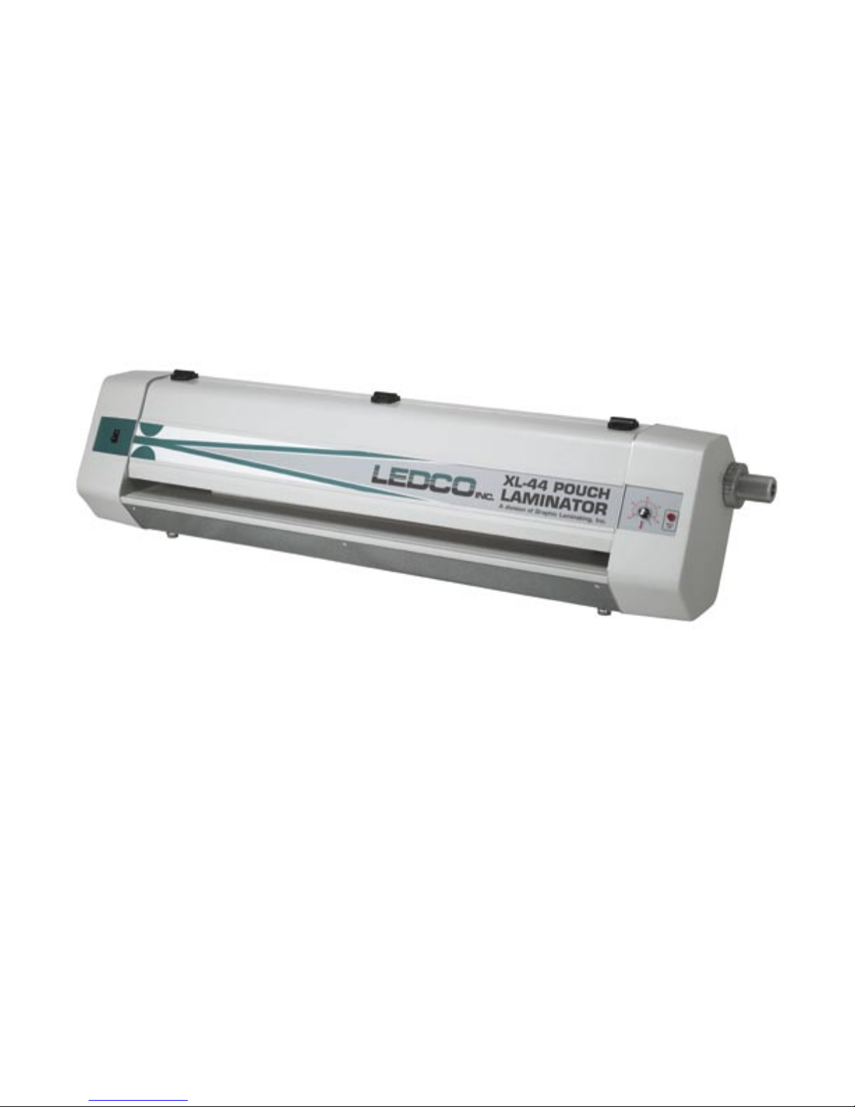
44” POUCH LAMINATOR
Operation
Manual

TABLE OF CONTENTS Page No.
1.0 INTRODUCTION 2
1.1 Features and benefits 3
1.2 Specifications 4
1.3 Principles of operation 5
1.4 Warranty 6
2.0 UNPACKING AND INVENTORY 8
3.0 SAFETY PRECAUTIONS 10
4.0 SETUP & OPERATION 12
4.1 Warm up to operating temperature 12
4.2 Pouch Laminating 12
4.3 Mounting & Laminating 14
4.4 Mounting 15
5.0 MAINTENANCE 16
5.1 Monthly Service Schedule 16
5.1.2 Rubber Roll Cleaning 16

1.0 INTRODUCTION
The 44” Pouch Laminator, when used in conjunction with mounting boards and
pouches is designed to provide a quality lamination using a wide range of papers and
materials. Common applications include but are not limited to: maps, digital imaging,
packaging, posters, menus, instructional aids, signs, presentation materials, photographs, copies (B&W or color), prints, flyers, promotional sheets, and many other
items.
To assure the best performance from your new laminator, please follow the safety,
installation, operation, and maintenance instructions in this manual. Read the manual
before using the laminator. Keep the manual with the machine and periodically review
the instructions. This manual also contains the warranty. Additional copies are available from the manufacturer.
We take this opportunity to thank you for selecting this Pouch laminator and to assure
you of our commitment to your satisfaction with our products.
As you unpack your new laminator, please complete the following information. Always
have this information ready when calling.
Dealer Where Purchased_____________________________________________
InstallationDate______________________________Serial#__________________
Ledco, Inc. 4265 North Main Street Hemlock, NY 14466
Fax: 585-367-2978 Phone: 585-367-2392
Web: ledcoinc.com E-mail: ledco@ledcoinc.com
2

1.1 FEATURES & BENEFITS
Your new pouch laminator has several standard features that set it apart from other
models
• Variable Heat Control The heat may be adjusted by the turn of a knob from 200
to 400 degrees Fahrenheit.
• Rubber Roll Adjustment from 0 to 1 1⁄2” The roll height adjustment graduations
are 0, 1/16, 1/8, 3/16, 1/4, 3/8, 1/2, 5/8, 3/4, 1, 1 1/4, 1 1/2.
3

1.2 SPECIFICATIONS
US Europe
Maximum laminating width 44” 1117mm
Speed 1 FPM .3 MPM
Maximum laminating thickness up to 1 1⁄2” up to 38mm
Dimensions 66L 16H 19W 1677mm L
406mm H
483mm W
Shipping Dimensions 72L 24H 26W 1829mm L
609mm H
660mm W
Weight/Shipping weight 130/200 Lbs. 59/91 Kg
Power Supply Requirements 110-125V Model 208-240V Model
110V 20 amp single phase
50/60Hz 50/60Hz 15 amp
Supply connector 125V 208-240V
NEMA 5-20R NEMA L6-20R
4

1.3 PRINCIPLES OF OPERATION
Pouch Laminating Two sheets of film are put together with thermal adhesive facing
each other and sealed at one edge forming a pouch. An item to be laminated is placed
between these two sheets of film. The pouch with the item to be laminated is placed
on a sled and slid into the pouch laminator. The pouch laminator has one set of rolls.
The bottom roll is cold and driven. The top roll is heated and idles. When the sled with
pouch intact is slid into the laminator, the top and bottom rubber rolls come in contact.
The bottom roll pulls the sled through and the top roll heats the pouch and activates the
thermal adhesive. The film’s adhesive is pressed into the ink and fibers on the surface
of the item being laminated.
Mounting & Laminating One sheet of laminating film is sealed to the lead edge of a
mounting board. The thermal adhesive on the board and the thermal adhesive on the
film, face each other. An item to be mounted and laminated is placed between the film
and the board. When the board is slid into the laminator, the top and bottom rubber
rolls come in contact with the mounting board. The bottom roll pulls the board through
and the top roll heats the film. The film’s adhesive and the board’s adhesive are
pressed into the ink and fibers on the surface of the item being mounted.
Mounting – Only The mounting board has a thermal adhesive on one side. An item to
be mounted is placed on the thermal adhesive side of the mounting board. A release
liner sheet with silicon coating on one side is placed over the surface of the item and
covering the entire board (with the silicon surface facing item and board to prevent
adhesive from the mounting board transferring to the top heated laminating roll). When
the board is slid into the laminator, the top and bottom rubber rolls come in contact with
the mounting board. The bottom roll pulls the board through and the top roll heats the
item to be mounted and the mounting board. The board’s adhesive activates and is
pressed into the ink and fibers of the item being mounted.
5
 Loading...