

Quick
Start
Guide
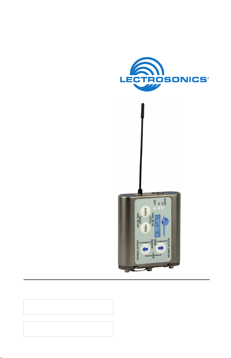
Watertight Transmitter
WM
Fill in for your records:
Serial Number:
Purchase Date:
U.S. Patent 7,225,135
This guide is intended to assist with
initial setup and operation of your
Lectrosonics product.
For a detailed user manual, download the most current
version at:
www.lectrosonics.com/manuals
6 July 2012

Controls and Functions
Modulation
Audio
Input Jack
PWR LED
LCD Screen
The display is a highly visible backlit LCD with screens for making all setup and level
adjustments. The transmitter can be powered up with or without the RF output turned
on. With the RF output turned off, all adjustments can be made without creating interference for other wireless systems in the vicinity.
For normal powering up and down, a countdown appears in the LCD. The buttons must
be held in for the duration of the countdown, which helps to prevent accidentally turning
the transmitter on or off.
LEDs
AUDIO Button
Power LED
The PWR LED glows green when the battery is good. The color changes to red when
there is about 30 minutes of operation left with the recommended lithium battery. An
alkaline battery will have about 20 minutes of life left. When the LED begins to blink red,
there are only a few minutes of life.
Note: A NiMH rechargeable battery will give little or no warning when it is depleted. If you wish to use
NiMH batteries, we recommend trying fully charged batteries in the unit and using the battery timer feature
available in most receivers to determine the available operating time.
A weak battery will sometimes cause the PWR LED to glow green immediately after
the unit is turned on, but will soon discharge to the point where the LED will turn red or
the unit will turn off completely. When the transmitter is in SLEEP mode, the LED blinks
green every few seconds.Audio Input Jack this is a threaded locking connector
that accepts the Lectrosonics watertight WP connector.
UP Arrow
LCD
FREQ Button
Battery Compartment
Caps
DOWN
Arrow
Battery Compartments and Thumb Screws
The large knurled thumbscrews retain the batteries and maintain solid battery contact.
The lanyard keeps the battery caps attached, but it can be removed if desired using a
1/16 inch hex key (Allen wrench).
Modulation LEDs
Proper input gain adjustment is critical to ensure the best audio quality. Two red/green
LEDs will glow to accurately indicate modulation levels. The input circuitry includes a
wide range DSP-controlled limiter to prevent distortion during high peak levels.
It is important to set the gain (audio level) high enough to achieve full modulation during
louder peaks in the audio. The DSP-controlled limiter can handle peaks over 30 dB
above full modulation. Full modulation is indicated when the -20 LED first turns red.
With an optimum setting, the -20 LED will flicker red during operation. If the LEDs never
flash red, the gain is too low.
LECTROSONICS, INC.2

Signal Level -20 LED -10 LED
Less than -20 dB Off Off
-20 dB to -10 dB
-10 dB to +0 dB
+0 dB to +10 dB
Greater than +10 db
Red Red
Green Off
Green Green
Red Green
AUDIO Button
The AUDIO button is used to display the gain and low frequency roll-off settings. The
UP and DOWN arrows adjust the values. This button is also used with the FREQ button
to enter standby mode and to power the transmitter on or off.
FREQ Button
The FREQ button displays the selected operating frequency and also toggles the LCD
between displaying the actual operating frequency in MHz and a two-digit hexadecimal
number that corresponds to the equivalent Lectrosonics Frequency Switch Setting.
This button is also used with the AUDIO button to enter standby mode and to power the
transmitter on or off.
Up/Down Arrows
The Up and Down arrow buttons are used to select the values on the various setup
screens and to lock out the control panel. Pressing both arrows simultaneously enters
the lock countdown. When an attempt is made to change a setting while the control
panel is locked, a message will flash on the LCD as a reminder that the unit is locked.
Once locked, the buttons can only be unlocked by removing the battery, or with the RM
remote control.
Antenna
The fixed whip antenna is made of a flexible, woven, galvanized steel mesh cable.
Preventing Corrosion
Whenever the transmitter has been exposed to moisture or perspiration, follow the
instructions below to minimize the risk of corrosion.
DRY THE UNIT BEFORE REMOVING THE MICROPHONE CONNECTOR OR BATTERY CAPS.
If the transmitter has been exposed to salt water, rinse it with fresh water and then dry it
thoroughly with a clean paper towel or cloth.
Dry the exterior of the transmitter with a clean paper towel or cloth. Remove all moisture
around the battery caps and microphone cable connector.
After removing the battery caps and microphone connector, wipe off any residual moisture around the battery compartment and microphone jack openings and on the battery
caps and microphone connector.
®
The O-rings should be coated with Vaseline
each use to ensure the seals are watertight.
DO NOT USE ANYTHING OTHER THAN PURE PETROLEUM JELLY TO LUBRICATE THE O-RINGS.
Silicon-based lubricants will dissolve the O-rings.
Store the unit with no batteries installed, battery caps removed and the microphone
disconnected. This will allow any buildup of humidity and moisture to evaporate.
*Vaseline is a registered trademark of Conopco, Inc
www.lectrosonics.com 3
or an equivalent petroleum jelly* before

Battery Compartments
The battery compartments are a rugged, straightforward design with a recessed entry
that captures the O-ring on the cap. The spring contact on the cap maintains solid
contact on the battery regardless of its exact length.
The O-rings should be kept clean and dry, and coated with petroleum jelly on a regular
basis. See page 11 of the manual on line for more information on preventing corrosion.
Attaching and Removing the Michrophone
The threaded WP watertight plug on the microphone cable fits into a recessed jack on
the top panel. The recess in the opening retains the O-ring when the plug is tightened.
The Lectrosonics M152WP lavaliere microphone is supplied with the WP plug already
installed. Other microphones can also be terminated with this plug by following the
instructions included with the WP connector kits.
Treat O-ring with petroleum jelly before connecting (see above)
Operating Instructions
Power Up and Boot Sequence
Simultaneously press and hold the AUDIO and FREQ buttons until the startup count
is completed. The screen will display a count from 1 to 3 as the unit boots up, then it
switches to the Audio screen. As the unit turns on, the Modulation LEDs and PWR LED
all glow red, then green, and then revert to normal operation.
LECTROSONICS, INC.4

The LCD displays a boot sequence which consists of four screens ending with the
audio screen similar to this example:
• Companyname:Lectro
• Frequencyblk/Firmware
Ver.:b21r1.1
• Powerlevel:Pr100
• Compatibilitymode:CP400
• Audio(Inputgain):Aud22
Power Down
Simultaneously press and hold the AUDIO and FREQ buttons while
The screen will display a countdown from 3 to 1 and the unit will then turn off.
Note: If the AUDIO and FREQ buttons are released before the LCD goes blank at the end
of the countdown, the unit will not turn off. Instead, it will stay energized and the display will
return to the previous screen.
observing that the word “OFF” appears in the LCD along with a counter.
Standby Mode
Quickly press both AUDIO and FREQ buttons to enter the “standby”
mode. In this mode the RF output is turned off so adjustments can be
location. The LCD displays rf OFF to remind you that the unit is not transmitting.
Use the AUDIO and FREQ buttons to access the various setup screens. When the
adjustments are complete, press both the AUDIO and FREQ buttons briefly to save the
settings and turn the unit off.
made without interfering with other systems operating in the same
Compatibility, Output Power, Bias Voltage (phantom power)
and LCD Backlight
Four different setup screens are accessed in a setup mode that is accessed with a
special button sequence.
•CompatibilityMode
•OutputPower
•BiasVoltage(phantompower)
•LCDBacklightSettings
Hold the UP arrow button and simultaneously press the AUDIO and FREQ buttons. The
compatibility setup screen will appear. Each successive press of the AUDIO button will
step through the other three setup scree
ns.
Note: The unit is automatically set to “standby” in this setup mode, however, the rF OFF
reminder will not be displayed.
Hold the UP arrow
Then press the AUDIO and
FREQ buttons at the same
time
www.lectrosonics.com 5
button

Compatibility Mode
In addition to it’s native Digital Hybrid mode, the transmitter will operate with Lectrosoncs 100 Series, 200 Series and IFB receivers, as well as several analog receivers
from other manufacturers.
From this screen, use the UP and DOWN arrows to select the desired
mode.
•CP 100: 100 Series mode
•CP 200: 200 Series mode
•CP 3: Mode 3 (contact the factory for details)
•CP 400:400Seriesmode
•CP IFB: IFB Series mode
•CP 6: Mode 6 (contact the factory for details)
Output Power
Extended operating range and increased immunity to dropouts can be
selected at the expense of shorter battery life by setting the output
power to 250 mW. Reduced output power will decrease power consumption and extend
battery life at the expense of operating range and immunity to dropouts. Use the UP and
DOWN arrows to select the desired output power.
NOTE: See the specifications for typical operating times with different batteries and power
levels.
Bias Voltage (phantom power)
The transmitter features unique Servo Bias input circuitry that automatically adjusts the
current to maintain a selected bias voltage for the microphone. This effectively overcomes a traditional problem with variations in output levels and power supply currents
of different microphones.
Hold the UP arrow button, then press the Audio and Freq buttons together to enter the
setup screen with the RF output turned off.
Press the UP and DOWN arrows to select the desired setting:
•PH 2 Bias at 2 volts for electret mics
•PH 4 Biasat4voltsforelectretmics
•PH oFF Bias turned off for dynamic mics
•L InE Bias turned off; live level impedance
Thecorrectbiasvoltagewillbespeciedbythemicrophonemanufacturer.4voltsis
typical for most electret lavaliere microphones. 2 volts is preferred by some mic manufacturers such as Countryman for the models B6 and E6.
LCD Backlight Settings
The backlight on the display can be set to stay on all the time or to turn
off after either 30 seconds or 5 minutes of inactivity on the panel
button is pressed. Use the UP and DOWN arrow buttons to select the desired setting.
switches. The backlight will turn on and the timer will start over when a
LECTROSONICS, INC.6

LF Roll-off and Gain
The Audio screen will appear after the boot sequence into the normal mode. When
turned on into the “standby” mode, rf OFF will appear on the display and pressing the
AUDIO button will switch to the Audio screen.
TheAudioscreenisusedtoadjustinputgainfrom0to+44dB,andthelowfrequency
roll-off from 35 to 150 Hz. Each time the AUDIO button is pressed, the display will
switch back and forth between the two screens. Press and hold the AUDIO button and
use the UP and DOWN arrows to make adjustments.
Adjusting the Low Frequency Roll-off
It is possible that the low frequency roll-off point could affect the gain
setting, so it’s generally good practice to make this adjustment before
selecting the desired roll-off frequency with the UP and DOWN arrows. The roll-off
frequency can be set to 35, 50, 70, 100, 120 and 150 Hz.
Adjusting Audio Level (Gain)
Once set, the transmitter’s audio level setting should not be used to control the volume
of your sound system or recorder levels. This gain adjustment matches the transmitter
gain with the microphone’s output level, the user’s voice level and the position of the
microphone.
It is desirable to set the gain so that some limiting occurs on louder peaks. The limiter
is very transparent and it’s effect is not audible until the system is close to overload. In
other words, don’t be shy about turning up the gain. In fact, it is a good idea to turn the
gain up to maximum and listen for distortion or compression to get a feel for how much
headroom the system actually has.
adjusting the input gain. Press and hold the AUDIO button while
The audio input level (gain) can be adjusted with the unit in the
“standby” mode or while powered up in normal operation. The control
panel Modulation LEDs indicate the audio level and limiter activity.
Signal Level 20 LED -10 LED
Less than -20 dB Off Off
-20 dB to -10 dB
-10 dB to +0 dB
+0 dB to +10 dB
Greater than +10 db
Note: Different voices will usually require different gain settings, so check this adjustment
as each new person uses the system. If several different people will be using the transmitter
and there is not time to make the adjustment for each individual, adjust it for the loudest
voice.
Green Off
Green Green
Red Green
Red Red
www.lectrosonics.com 7

LIMITED ONE YEAR WARRANTY
The equipment is warranted for one year from date of purchase against defects in
materials or workmanship provided it was purchased from an authorized dealer. This
warranty does not cover equipment which has been abused or damaged by careless
handling or shipping. This warranty does not apply to used or demonstrator equipment.
Should any defect develop, Lectrosonics, Inc. will, at our option, repair or replace any
defective parts without charge for either parts or labor. If Lectrosonics, Inc. cannot
correct the defect in your equipment, it will be replaced at no charge with a similar new
item. Lectrosonics, Inc. will pay for the cost of returning your equipment to you.
This warranty applies only to items returned to Lectrosonics, Inc. or an authorized
dealer, shipping costs prepaid, within one year from the date of purchase.
This Limited Warranty is governed by the laws of the State of New Mexico. It states the
entire liablility of Lectrosonics Inc. and the entire remedy of the purchaser for any
breach of warranty as outlined above. NEITHER LECTROSONICS, INC. NOR
ANYONE INVOLVED IN THE PRODUCTION OR DELIVERY OF THE EQUIPMENT
SHALL BE LIABLE FOR ANY INDIRECT, SPECIAL, PUNITIVE, CONSEQUENTIAL,
OR INCIDENTAL DAMAGES ARISING OUT OF THE USE OR INABILITY TO USE
THIS EQUIPMENT EVEN IF LECTROSONICS, INC. HAS BEEN ADVISED OF THE
POSSIBILITY OF SUCH DAMAGES. IN NO EVENT SHALL THE LIABILITY OF
LECTROSONICS, INC. EXCEED THE PURCHASE PRICE OF ANY DEFECTIVE
EQUIPMENT.
This warranty gives you specific legal rights. You may have additional legal rights which
vary from state to state.
 Loading...