

Page 1

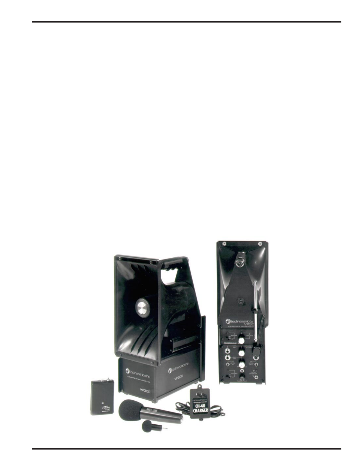
Voice Projector
VP300, FM-AV5 (VP300W) & R300
Portable Public Address System
S/N 300216 and up
OPERATING INSTRUCTIONS
and trouble-shooting guide
LECTROSONICS, INC.
Rio Rancho, NM
www.lectrosonics.com
ISS. 6, 11-84
Page 2

IMPORTANT BATTERY INFORMATION
FAILURE TO OBSERVE THE FOLLOWING PRECAUTIONS CAN CAUSE PREMATURE BATTERY FAILURE WHICH IS NOT COVERED BY THE WARRANTY.
The Rechargeable batteries in this unit should be recharged at least once every six
months even if not used.
The batteries should never be completely discharged. Keeping the batteries fully
charged when not in use is the best way to ensure longest battery life and prevent
premature failure.
BATTERIES THAT HAVE BEEN TOTALLY DISCHARGED MAY NOT ACCEPT A
CHARGE. IN SOME CASES A BATTERY THAT APPEARS TO BE DEAD CAN BE
SAVED BY PROLONGED CHARGING - UP TO TEN DAYS.
CAUTION
The fuse will blow if a horn or speaker is unplugged or plugged into the VP300 while
the power is on.
FEDERAL COMMUNICATION COMMISSION REGULATIONS
The Lectrosonics M30 Series Transmitters comply with part 91.555 of F.C.C. Rules
and Regulations for use as wireless microphones.
F.C.C. Regulations require that each M30 Series Transmitter be licensed by the
owner. F.C.C. Form 400, together with instructions for its completion are shipped with
each transmitter. This form should be submitted to the F.C.C. prior to placing your
wireless system into operation.
2
Page 3
1. GENERAL
Portable Public Address System
1.01 This manual contains the functional description and operating procedures for the Lectrosonics, Inc. Voice
Projector Models VP300 and FM-AV5 Sound Systems.
2. EQUIPMENT DESCRIPTION
2.01 VP300
2.01.1 The VP300 is a portable public address system designed primarily for outdoor use. The unit is equipped with
a wide angle reentrant horn for efficient sound dispersion and high capacity built-in rechargeable battery pack. The
unit may be operated from the battery pack, a vehicle 12 volt cigarette lighter receptacle, or from 115 VAC, 50-60 Hz
using the charger supplied with the unit. 230VAC 50-60 Hz chargers are available from the factory.
2.01.2 The VP300 is equipped with two microphone input jacks with individual volume controls which allows two
microphones to be used.
2.01.3 The speaker output jacks are wired to accomodate either one or two 8 Ohm speakers or horns.
2.01.4 The VP300 is designed to accept the plug-in R300 Wireless Receiver Module which allows the system to be
operated as either a conventional P.A. system with a wired microphone or as a wireless microphone sound system
using the remote transmitter and microphone supplied with the R300 module.
2.01.5 The VP300 comes with an M121S hand-held cardioid microphone, 16 foot MM-16 microphone cord and CH40 charger.
Rio Rancho, NM – USA
3
Page 4

2.01.6 VP300 SPECIFICATIONS
AMPLIFIER: • All silicon transistor - 33 Watt RMS output into 8 Ohms
• Frequency Response - 200 to 20,000 Hz, +/- 1dB.
SOUND PROJECTOR: Wide angle 11" reentrant horn with an S.P.L. rating of 125dB.
POWER SOURCE: • Rechargeable 12 Volt, 8 amp-hour self contained battery pack provides up to 60 hours
continuous operation per charge.
• UL and CSA approved CH-40 charger.
MICROPHONE: High quality cardioid microphone with on-off switch and detachable 16' cord.
CONSTRUCTION: All metal with high-impact Cycolac horn.
SIZE AND WEIGHT: 15 3/4" high x 6 1/2" wide x 9" deep; 17 pounds.
INPUTS: • Two microphone inputs, 1/4" phone jacks with individual volume controls.
• High level - miniature phonograph jack.
• Speaker - two 1/4" stereo phone jacks for connections to either one or
two 8 Ohm speakers.
2.02 FM-AV5 (VP300W)
2.02.1 The FM-AV5 is a basic VP300 public address system equipped with an optional Freedomike R300 Wireless
Microphone Conversion Kit. The kit consists of a plug-in wireless receiver module with telescoping whip antenna, a
Lectrosonics M30 transmitter and M118 microphone with accessories or the optional M116 microphone with accessories.
2.02.2 M116 MICROPHONE
The M116 Microphone is a miniature electret cardioid microphone intended primarily for lavalier use when used with
the FM-AV5 Wireless Microphone Sound System. The M116 comes with a C-20 lavalier clip, MC-37 cord and RK-45
windscreen. The M116 is available, at no additional cost, as a substitute for the standard M118 microphone when
ordered with the FM-AV5 System.
2.02.3 M118 MICROPHONE
The M118 Microphone is a miniature electret cardioid microphone intended primarily for close talking hand-held use
with the FM-AV5 Wireless Microphone Sound System. It may be used as a lavalier microphone with the FM-AV5, but
is inferior to the M116 for that purpose. The M118 is furnished as standard with the FM-AV5 unless another microphone is specified at time of order. The m118 is similar in appearance to the M116, except that it has a gold band on
its base. It comes with a C-20 lavalier clip, MC-37 cord and RK-45 windscreen.
2.02.4 M131SW MICROPHONE
The M131SW Microphone is an electret, cardioid microphone with on-off slide switch. It is available as an option for
M30 users who prefer a hand-held microphone. It comes with an MC-38 cord and RK-51 windscreen.
2.02.5 M30 SERIES WIRELESS TRANSMITTER
2.02.5.1 The M30 Series Wireless Transmitter is a crystal controlled low-power FM transmitter with a sefl-contained
antenna. It is available in two models:
(a) M30 - Uses a replaceable 9 Volt alkaline battery.
(b) M30PB - Same as the M30 except it is equipped with a spring-loaded "push-to-talk" switch.
2.02.5.2 The M30 Series Wireless trnasmitter transmits on a single frequency in the 30MHz to 50MHz range. The
operating frequency is printed on a label on the bottom of the transmitter case and must match the frequency of its
companion receiver.
4
Page 5

Portable Public Address System
2.02.5.3 All M30 Series Transmitters are designed to operate with the Lectrosonics M116 and M118 microphones.
They will also operate with the hand-held M131SW Microphone using an MC-38 Microphone cord.
2.02.5.4 Satisfactory operation up to a range of 200 feet can be expected under conditions normally encountered.
This range may extend to 500 feet under optimum conditions.
2.02.6 M30 TRANSMITTER SPECIFICATIONS
RF OUTPUT: 50 milliwatt, FM modulated.
ANTENNA: Internal ferrite dipole radiator
CARRIER FREQUENCY STABILITY: 0.01% crystal controlled
POWER SOURCE: M30 - 9 Volt alkaline battery provides 20 hours of operation at
4 hours per day or 15 hours continuous operation.
DIMENSIONS: 2 1/4" wide x 3 1/4" high x 1 1/16" thick.
2.02.7 R300 RECEIVER MODULE SPECIFICATIONS
ANTENNA: 54" telescoping whip
CONTROLS: Wireless microphone volume control and on-off switch with green LED
carrier indicator lamp.
RF SENSITIVITY: 0.5 microvolt for 20dB quieting.
SIGNAL-TO-NOISE RATIO: • 70dB at 40dB input (100 microvolt)
• 53dB at 20dB input (10 microvolt)
• 32dB at 0dB input (1 microvolt)
UNICHANNEL SELECTIVITY: • 6 pole crystal filter
• Adjacent channel rejection, 18dB at 20kHz from carrier. Alternate channel
rejection, 50dB at 40kHz from carrier.
• Image rejection better than 80dB
• Spurious response rejection better than 80dB.
AM REJECTION: Better than 60dB.
FREQUENCY STABILITY: 0.005%, crystal controlled
SQUELCH SYSTEM: Factory set, no adjustments required.
3. VP300 OPERATION
3.01 By observing a few simple rules when setting up the VP300 you will be assured of optimum performance.
(a) Make sure the battery pack is fully charged before setting up.
(b) Elevate th unit for maximum sound coverage. The VP300 is equipped with a 1/2" diameter socket which fits the
Lectrosonics Model SS-4 Tripod Stand.
(c) Locate the VP300 so that the sound from the speaker cannot readily enter the microphone.
Rio Rancho, NM – USA
5
Page 6

3.02 Charge the unit, perform the following procedures:
(a) Insert the CH-40 charger cord plug fully into the CH-40 jack.
(b) Plug the charger into the AC wall socket. The green lamp will light and remain lit if the battery pack requires
charging. If the battery pack is fully charged, the lamp will light momentarily and then go dark. A fully discharged
battery pack will require approximately 30 hours to bring it up to full charge. Under normal usage, an overnight
charge should be adequate. The unit should always be charged until the green lamp goes out.
3.03 For battery only operation, disconnect the CH-40 charger. In this mode of operation a fully charged battery pack
will typically provide 12 hours of operation.
3.04 To operate the VP300 from a vehicle 12 volt cigarette lighter receptacle, plug the adapter cord 21329 first in the
EXT. 12VCD IN jack on the VP300 and then into the lighter receptacle.
3.05 Plug the microphone cord into the MAIN MIC microphone jack and the other end of the cord into the microphone.
NOTE
A second microphone may be connected into the AUX MIC jack.
3.06 Operate the MAIN POWER switch to ON. The red lamp will light.
3.07 Hold the microphone so that it is pointed directly toward the chin and is within six inches of the speaker's mouth.
3.08 Rotate the associated volume control clockwisw until intelligible sound, at an adequate level, is available at the
most distant point a listener is expected. A setting higher than necessary increases the chance of "feedback" occurring. The distance between the mouth and microphone affects the required volume control setting - the closer the
microphone, the lower the setting.
3.09 HI LEVEL INPUT AND OUTPUT
3.09.1 HI LEVEL IN
The HI LEVEL IN is an RCA phonograph jack which may be used with line level, auxiliary or high level outputs from
tape decks, cassette players, hi-fi systems and other P.A. systems. Use a Lectrosonics MM-36 or MM-50 cord.
3.10 SPEAKER CONNECTIONS
3.10.1 The VP300 is equipped with two 1/4" stereo phone jacks that are arranged to accomodate either one or two 8
Ohm speakers or horns.
3.10.2 The upper speaker jack is intended for use with a single speaker and provides a full 33 Watts of output power.
3.10.3 When a speaker is plugged into both the upper and lower jacks, 16.5 Watts of power is supplied to each jack.
3.10.4 Maximum distance and sound penetration will be obtained by using an 8 Ohm reentrant horn(s) such as the
Lectrosonics H300. Horns are inherently more efficient than coaxial speakers. However, due to their limited frequency
response, the sound from a horn is not as pleasing to the ear as the sound from a coaxial speaker.
3.10.5 When high fidelity performance is of primary importance, the Lectrosonics ES300 Extension Speaker Column
should be used.
4. FM-AV5 (VP300W) SYSTEM OPERATION
4.01 GENERAL CONSIDERATIONS AND PRECAUTIONS
4.01.1 When setting up your FM-AV5 FREEDOMIKE Wireless Microphone System, keep in mind that there is, most
likely, a certain location for your unit which will result in optimum system performance. This is particularly true inside a
building where many performance disturbing influences are encountered.
6
Page 7

Portable Public Address System
4.01.2 Determining the absolute optimum location for the FM-AV5 and M30 transmitter is a matter of trial and error.
However, by observing a few simple rules, satisfactory system performance can be obtained with a minimum of effort.
(a) Locate the FM-AV5 at least six feet away from walls and large metal objects such as blinds and heating/air
conditioning ducts.
(b) Locate the FM-AV5 at least four feet above the floor and at a point where the transmitter is in sight.
(c) Locate the FM-AV5 as far away as possible from fluorescent lamps.
(d) If practical, locate the FM-AV5 away from roads carrying motor vehicles.
(e) Locate the FM-AV5 away from dead spots. These can be found by experimentation as discussed in paragraph
4.02.
(f) Locate speakers so that the emitted sound cannot readily enter the microphone.
4.01.3 "Feedback" is an undesirable howling or squealing sound which must be avoided. Two interacting factors
cause feedback. These are:
(a) The amount of system sound output coupled back into the amplifier system via the microphone and receiver.
(b) The gain setting of the R300 module VOLUME control.
Feedback can be prevented by ensuring adequate separation between the microphone and the sound system speakers. If gain is increased the separation must be increased. Holding the microphone closer to the mouth will allow the
gain to be decreased and thereby reduce the probability of feedback.
4.02 DEAD SPOTS
4.02.1 "Dead spots" are locations where reception of the transmitted radio waves is poor. The two main reasons for
dead spots are:
(a) An object between the transmitter and receiver is either absorbing or reflecting the transmitted radio waves so
that they cannot reach the antenna of the receiver.
(b) Refelective surfaces between the transmitter and receiver cause the radio waves to arrive at the receiving
antenna by multiple paths. This can result in poor reception and sometimes, no reception at all.
4.02.2 Finding dead spots is simply a matter of experimenting with the location of the FM-AV5 relative to the location
of the transmitter. If the transmitter location is stationary, the FM-AV5 is moved around until the area of best reception
is found.
4.02.3 If the person using the transmitter is going to be moving around, he should determine by actual experimentation, any dead spots that exist in the area he plans to cover. Once they are located, they can be avoided during the
actual presentation.
NOTE
USE OF MICROPHONES OTHER THAN LECTROSONICS M116, M118
AND M131SW MAY RESULT IN INFERIOR SYSTEM PERFORMANCE.
5. M30 SERIES TRANSMITTER OPERATION
5.01 GENERAL
5.01.1 It is characteristic of FM receivers that they can receive a transmission from only one transmitter at a time.
Simultaneous use of more than one M30 transmitter with a single receiver will result in a loud squeal. If the individuals
using the microphones could be disciplined to turn one transmitter off before another is turned on, it would be possible
to use multiple transmitters on the same frequency, however, this practice is not recommended.
Rio Rancho, NM – USA
7
Page 8

5.01.2 For best system operation, the M118 and M131SW microphones should be less than three inches from the
speaker's mouth. A distance greater than three inches will require a higher volume control setting which increases the
probability of feedback.
5.01.3 The optional M116 Microphone is recommended for lavalier use.
5.02 M30 AND M30PB BATTERY INFORMATION AND REPLACEMENT
5.02.1 M30 and M30PB Transmitters use a replacable 9 Volt alkaline battery (Eveready No. 522, Mallory MN1604 or
equivalent) which will provide approximately 15 hours of continuous operation or 20 hours of operation at a rate of 4
hours per day. While other batteries will work for awhile, they will result in inferior overall performance and their use is
not recommended.
5.02.2 As the stored energy in the battery is used up during transmitter operation, the battery voltage will start to
drop causing the transmission range to gradually decrease until total loss of reception will occur at the receiver. To
avoid interruption of a presentation due to battery failure, it is recommended that a log of operating time be kept so
that the battery can be replaced when it approaches the end of its expected life. In addition, it is wise to keep a spare
battery with the transmitter. In critical applications, play it safe and install a new battery.
5.02.3 To replace the battery in the M30 and M30PB Transmitter, perform the following procedures:
CAUTION
WHEN REPLACING THE BATTERY, USE CARE TO AVOID PLACING
UNDUE STRAIN ON THE SNAP-ON BATTERY CONNECTOR WIRES.
(a) Verify that the toggle switch on the top of the transmitter is in the OFF position.
(b) With a narrow flat-blade screwdriver remove the slotted-head screw from the transmitter cover.
(c) Lift off and set aside the transmitter cover.
(d) Remove the battery from its compartment.
(e) Use the screwdriver blade to disconnect the snap-on connector from the battery terminals.
(f) Snap the connector on a new battery and install.
(g) Replace and secure the cover.
5.03 USING THE M30 SERIES TRANSMITTER WITH THE M118 AND M116 MICROPHONES
5.03.1 Unless specified otherwise at the time of order, the M118 Microphone is furnished with the FM-AV5 Wireless
Microphone Sound System. The M118 is identified by the gold band around its base. The M118 is intended primarily
to be used for close talking hand-held operation with the microphone plugged directly into the M30 Series Transmitter.
The microphone should be kept within three inches of the speaker's mouth.
5.03.2 If desaired the M118 may be connected to the M30 Transmitter with the MC-37 cord. When connected in this
manner the M30 may be clipped to the belt, dropped in a pocket or taped to the body.
5.03.3 The optional M116 Microphone is intended for lavalier use with the FM-AV5 System. The M116 is similar in
appearance to the M118 except that it is all black. The M116 is used with the C-20 lavalier clip and connected to the
M30 Transmitter with the MC-37 cord. The M116 should be clipped to the clothing about six inches from the speaker's
mouth.
5.03.4 When using the M30 Transmitter, operate the toggle switch to the ON position. The green lamp will light on the
R300 receiver module indicating that the transmitter is sending a signal. When using the M30PB Transmitter, the
spring-loaded toggle switch must be held in the ON position while transmitting.
5.03.5 When not in use, disconnect the MC-37 cord from the microphone and transmitter. Store the cord in a loose
coil and avoid sharp bends at the junction of the cord and the plugs.
8
Page 9

Portable Public Address System
5.04 USING THE M30 TRANSMITTER WITH THE M131SW MICROPHONE
5.04.1 When the M131SW Microphone is used with an M30 Series Transmitter, it must be connected to the transmitter with the MC-38 cord supplied.
6. R300 WIRELESS RECEIVER MODULE OPERATION
6.01 INITIAL ADJUSTMENTS
To place the R300 Wireless Receiver Module into operation, perform the following procedures:
(a) Extend the antenna fully and ensure it is not touching any metal objects.
(b) On the R300 module, rotate the VOLUME control fully counter-clockwise.
(c) On the VP300 AMplifier Module -
(1) Insert the CH-40 charger plug fully into the CH-40 IN jack. Plug the charger into the AC wall socket. The
green lamp will light and remain lit if the battery pack requires charging. If the battery pack is fully charged,
the lamp will light momentarily and then go dark.
(2) Operate the POWER switch to ON. The associated red POWER lamp will light. In this mode of operation the
unit is operating from AC power and the battery pack is being charged. If a power failure occurs, the unit
automatically switches over to battery operation.
(3) For battery only operation, disconnect the CH-40 charger. In this mode of operation a fully charged battery
pack will typically provide 12 hours of operation. One hour of charge will typically provide two hours of operation.
(d) On the R300 module, operate the POWER switch to ON. The associated red POWER lamp will light.
(e) On the M30 transmitter, operate the toggle switch to ON.
(f) On the R300 module, rotate the VOLUME control clockwise until the green lamp lights.
6.02 ADJUSTING THE R300 VOLUME
6.02.1 Establish the speaking location and, while transmitting from that position, adjust the VOLUME control on the
R300 module until intelligible sound, at an adequate level, is available at the most distant point a listener is expected.
6.02.2 Avoid feedback by adjusting the VOLUME control no higher than necessary. A setting between 20 percent and
60 percent of full range will provide the best signal-to-noise ratio with the lowest distortion.
6.03 OPERATING THE FM-AV5 BY MORE THAN ONE PERSON
6.03.1 If desired, the FM-AV5 may be operated by up to three persons - two using M121S microphones plugged into
the VP300 amplifier module and the third person using the M30 Series Transmitter with the appropriate microphone.
6.04 USING THE M30 NEAR THE FM-AV5
6.04.1 When it is necessary to operate the transmitter at close range, a feedback problem may be encountered. This
can be minimized by using the Lectrosonics Model HM-142V Headset Microphone which has a volume control. With
the HM-142V volume control and the R300 module volume control properly adjusted, it is possible to work within a
few feet of the receiver.
Rio Rancho, NM – USA
9
Page 10

VP300 and FM-AV5 ACCESSORIES AND REPLACEMENT PARTS
CAT. NO. ITEM DESCRIPTION USE
A-34 Lavalier Cord Neck cord for the RM-131S Microphones.
A-54 Antenna, telescoping, 54" Replacement antenna for R300 Wireless Module
C-20 Lavalier Clip Adapts M116 Microphone for lavalier use.
CH-12 (alternate) Charger/Battery Eliminator M30R Transmitters
CH-16 Charger/Battery Eliminator M30R Transmitters
CH-40 Charger/Battery Eliminator VP300 and FM-AV5
HM141V Headset Microphone w/Volume Control M30 Series Transmitters
MC-37 Microphone Cord for M116 and M118 Connects M116 & M118 Microphones to
M30 Transmitter.
MC-38 37" Microphone Cord Connects RM-121S Microphone to
M30 Series Transmitter.
MC-39 16' Microphone Cord Adapts HM141V, M116 and RM-116 Microphones
for use with VP300.
MM-16 16' Microphone Cable For RM-121S Microphone when connected to VP300.
MM-36 36" Cord, Male Phono Plugs For connecting to HI LEVEL jacks.
MM-50 50" Cord, Male Phono Plugs For connecting to HI LEVEL jacks.
RM-116 *Replacement M116 Microphone For use with M30 Series Transmitters.
Recommended for lavalier use with the FM-AV5.
RM-118 *Replacement M116 Microphone For use with M30 Series Transmitters.
Recommended for lavalier use with the FM-AV5.
RM121S *Replacement M121S Microphone For use with the VP300.
RM-131SW *Replacement M131SW Microphone For use with the M30 Series Transmitters.
RK-45 Windscreen for M116 & M118 Microphones
RK-51 Windscreen for RM-131 Microphone
22036 Fuse, 8 Amp (Buss AGC8 or equiv.)
40039 Battery (2 ea. required) Batteries should be replaced in pairs.
ES300 Extension Speaker Column Non-powered extension speaker, 8 Ohm impedance.
Same construction as A310. 50' cord. Tripod socket.
H300 Horn Wide angle 11" reentrant horn with a 125dB S.P.L.
rating, 8 Ohm impedance. 50' cord. Adjustable
mount with tripod socket for SS-4 Tripod Stand.
* Without accessories.
Note: ES300 speakers and H300 horns to be used with VP300 system up to S/N 300188 must be equipped with
standard 1/4" phone plugs. Specify at time of order.
10
Page 11

Portable Public Address System
SERVICE AND REPAIR
If your system malfunctions, you should attempt to correct or isolate the trouble before concluding that the equipment
needs repair. Make sure you have followed the setup procedure and operating instructions. Check out the interconnecting cords and then go through the TROUBLESHOOTING section in the manual
We strongly recommend that you do not try to repair the equipment yourself and do not have the local repair shop
attempt anything other than the simplest repair. If the repair is more complicated than a broken wire or loose connection, send the unit to the factory for repair and service. Don’t attempt to adjust any controls inside the units. Once set
at the factory, the various controls and trimmers do not drift with age or vibration and never require readjustment.
There are no adjustments inside that will make a malfunctioning unit start working.
LECTROSONICS’ service department is equipped and staffed to quickly repair your equipment. In warranty repairs
are made at no charge in accordance with the terms of the warranty. Out of warranty repairs are charged at a modest
flat rate plus parts and shipping. Since it takes almost as much time and effort to determine what is wrong as it does
to make the repair, there is a charge for an exact quotation. We will be happy to quote approximate charges by phone
for out of warranty repairs.
RETURNING UNITS FOR REPAIR
You will save yourself time and trouble if you will follow the steps below:
A. DO NOT return equipment to the factory for repair without first contacting us by letter or by phone. We need to
know the nature of the problem, the model number and the serial number of the equipment. We also need a phone
number where you can be reached 8 am to 4 pm (Mountain Standard Time).
B. After receiving your request, we will issue you a return authorization number (R.A.). This number will help speed
your repair through our receiving and repair departments. The return authorization number must be clearly shown
on the outside of the shipping container.
C. Pack the equipment carefully and ship to us, shipping costs prepaid. If necessary, we can provide you with the
proper packing materials. UPS is usually the best way to ship the units. Heavy units should be “double-boxed” for
safe transport.
D. We also strongly recommend that you insure the equipment, since we cannot be responsible for loss of or damage
to equipment that you ship. Of course, we insure the equipment when we ship it back to you.
Mailing address: Shipping address: Telephones:
Lectrosonics, Inc. Lectrosonics, Inc. Regular: (505) 892-4501
PO Box 15900 581 Laser Rd. Toll Free (800) 821-1121
Rio Rancho, NM 87174 Rio Rancho, NM 87124 FAX: (505) 892-6243
USA USA
We b: http://www.lectrosonics.com Email: sales@lectrosonics.com
Rio Rancho, NM – USA
11
Page 12

LIMITED ONE YEAR WARRANTY
LIMITED ONE YEAR WARRANTY
The equipment is warranted for one year from date of purchase against defects in
materials or workmanship provided it was purchased from an authorized dealer. This
warranty does not cover equipment which has been abused or damaged by careless
handling or shipping. This warranty does not apply to used or demonstrator equipment.
Should any defect develop, Lectrosonics, Inc. will, at our option, repair or replace any
defective parts without charge for either parts or labor. If Lectrosonics, Inc. cannot
correct the defect in your equipment, it will be replaced at no charge with a similar new
item. Lectrosonics, Inc. will pay for the cost of returning your equipment to you.
This warranty applies only to items returned to Lectrosonics, Inc. or an authorized
dealer, shipping costs prepaid, within one year from the date of purchase.
This Limited Warranty is governed by the laws of the State of New Mexico. It states the
entire liablility of Lectrosonics Inc. and the entire remedy of the purchaser for any
breach of warranty as outlined above. NEITHER LECTROSONICS, INC. NOR
ANYONE INVOLVED IN THE PRODUCTION OR DELIVERY OF THE EQUIPMENT
SHALL BE LIABLE FOR ANY INDIRECT, SPECIAL, PUNITIVE, CONSEQUENTIAL,
OR INCIDENTAL DAMAGES ARISING OUT OF THE USE OR INABILITY TO USE
THIS EQUIPMENT EVEN IF LECTROSONICS, INC. HAS BEEN ADVISED OF THE
POSSIBILITY OF SUCH DAMAGES. IN NO EVENT SHALL THE LIABILITY OF
LECTROSONICS, INC. EXCEED THE PURCHASE PRICE OF ANY DEFECTIVE
EQUIPMENT.
This warranty gives you specific legal rights. You may have additional legal rights which
vary from state to state.
LECTROSONICS, INC.
581 LASER ROAD
RIO RANCHO, NM 87124 USA
www.lectrosonics.com
August 14, 2002
(ISS. 6, 11-84)
 Loading...