

Page 1

VI24
Video Switcher Interface
OPERATING INSTRUCTIONS
and trouble-shooting guide
LECTROSONICS, INC.
Rio Rancho, NM
Page 2

INTRODUCTION
The VI24 Video Switcher Interface off ers flexible automated control of video s witchers based on the output status of up to eight Lectrosonics AM8 or AM16 mixers.
While its 24 independent logic outputs could be used to control almost anything, the
VI24 is intended primarily for use as a low-cost video-follows-audio system. Some
possible applications are:
• courtrooms
• board rooms
• panel discussions
• legislative sessions
• security systems
Using the accompanying software, you need only describe y our mixer setup and
then assign mixer input activity to trigger the VI24’s logic outputs. Your settings are
then sent to the VI24 and the unit is thus “programmed” for your specific needs.
TABLE OF CONTENTS
INTRODUCTION .................................................................................................. 2
FCC PART 15 NOTICE ........................................................................................ 3
FRONT PANEL CONTROLS AND FUNCTIONS ................................................ 3
REAR PANEL CONTROLS AND FUNCTIONS .................................................. 4
INSTALLING THE SOFTWARE ........................................................................... 4
INSTALLING THE HARDW ARE ........................................................................... 5
SETTING UP THE VI24 ....................................................................................... 6
SETTING UP THE VI24 FOR THE FIRST TIME................................................. 9
TROUBLESHOOTING ....................................................................................... 11
ACCESSORIES .................................................................................................. 11
SERIAL CABLE WIRING DIAGRAM ................................................................ 12
AMX CABLE WIRING DIAGRAM ...................................................................... 12
AMX Programming Notes ............................................................................. 12
SERIAL PORT COMMANDS AVAILABLE ........................................................ 13
SPECIFICATIONS .............................................................................................. 14
SERVICE AND REPAIR ..................................................................................... 15
RETURNING UNITS FOR REPAIR ................................................................... 15
WARRANTY ......................................................................................... Back co ve r
2
Page 3
Video Switcher Interface
FCC PART 15 NOTICE
This equipment has been tested and found to comply with the limits for a class B digital device, pursuant to Part 15
of the FCC Rules. These limits are designed to provide reasonable protection against harmful interference in a
residential installation. This equipment generates, uses and can radiate radio frequency energy and, if not installed
and used in accordance with the instructions, may cause harmful interference to radio communications. If this
equipment does cause harmful interference to radio or television reception, which can be determined by turning the
equipment off and on, the user is encouraged to try to correct the interference by one or more of the following
measures:
• Reorient or relocate the receiving antenna.
• Increase the separation between the equipment and receiver.
• Connect the equipment into an outlet on a circuit different from that to which the receiver is connected.
• Consult the dealer or an experienced radio/TV technician for help.
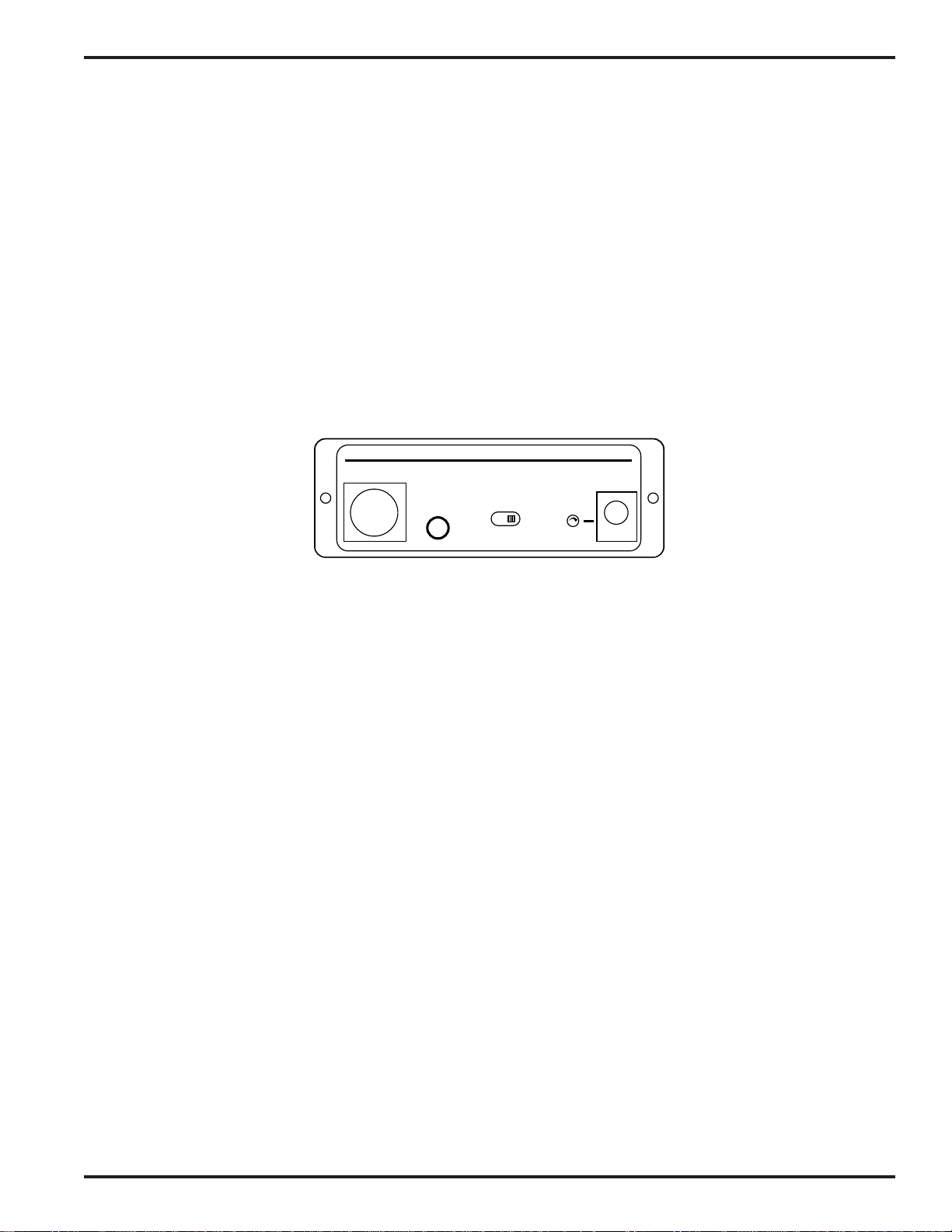
FRONT PANEL CONTROLS AND FUNCTIONS
LECTROSONICS VI 24
EXPANSION
PC PORT
(RS-232)
VIDEO SWITCHER INTERFACE
PWR (CH40)
TEST
RUN
EXPANSION JACK
The LecNet expansion jack is for connection to the mixers being monitored. It is not necessary to connect anything
to this jack while programming the VI24, though if a connection is available, the VI24 software can detect and display
information about any connected mixers.
PC PORT
The PC Port is used for programming and controlling the VI24 using the accompanying VI24 software. Simply
connect it to a serial port (e.g. COM1 or COM2) of the computer .
Note: It is possib le to use the VI24 software to create and store a configuration, then progr am the VI24 at a
later time. Thus, a setup can be conceived and created on a laptop computer en route to an event.
TEST/RUN SWITCH
The VI24 operates normally (and the led glows steadily) when the Test/Run switch is in the “run” position. In the
“test” position, the led flashes and each of the 24 logic outputs is asserted in turn for one second. After 24 seconds,
the cycle repeats, starting with the first logic output again. The test function is intended to assist the user in narrowing down problems. If the video switcher faithfully executes the functions associated with each of the output pins in
test mode, neither it nor the associated wiring is at fault. To exit test mode, simply return the switch to the “run”
position.
Note: The led can flash in run mode. See the section on the led for details.
LED
The led serves as a power and status indicator. In test mode, the led flashes once a second. Dur ing normal operation, the led glows steadily. The led flickers slightly during programming transf ers, to indicate activity. When the unit is
first powered on, the led may flash about five times while the memory is being initialized. This will not happen if the
memory was initialized during factory testing procedures.
POWER JACK
The VI24 requires a Lectrosonics CH-40 charger (included with the VI24) for power. While the VI24 has no power
switch, it uses very little power. It may safely be connected to a switched outlet such as a power strip in a rack.
Rio Rancho, NM – USA
3
Page 4
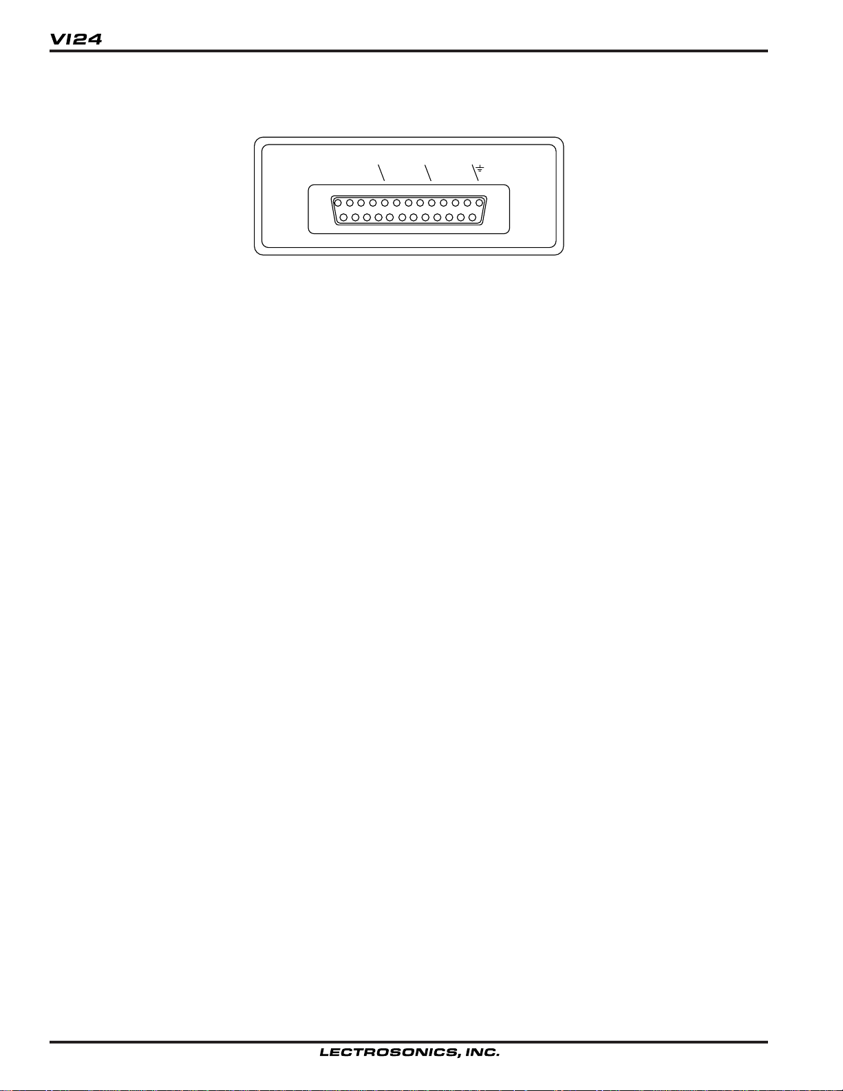
REAR PANEL CONTROLS AND FUNCTIONS
LOGIC
OUT
LOGIC OUTPUTS
On the rear of the VI24 is a male 25-pin D connector as is commonly used for computer interfaces. This is not a
serial, parallel or SCSI port, however. As the markings next to the connector show, one of the pins is ground, and the
others are the logic outputs, numbered 1 to 24. These are “open-drain” outputs: When the pin is “off”, there is no
connection to ground or to any other pin (it’s an open circuit). When the pin in “on”, it is shorted to ground. Thus, a
switch contact closure is electrically simulated.
Note: the popular “GPI” (General Purpose Interface) common to many popular video s witchers requires e xactly
these electrical characteristics. The output pins of the VI24 may be connected directly to GPI input pins.
1 2 3 4
5 6 7 8
9 10 11 12
13 14 15 16
17 18 19 20
21 22 23 24
INST ALLING THE SOFTW ARE
The VI24 software requires Microsoft Windows 3.1, Windows For Workgroups, Windows 95 or Windows NT . Y ou will
need approximately 4MB of av ailable hard disk space to install the application. You will also need an available serial
port to connect to the VI24.
Insert the floppy and run SETUP.EXE. On Windo ws 3.1 and Windows F or Workgroups, select “Run...” from the
Program Manager . On Windows 95 and NT, click the start menu, then select “Run...”. Type in x:\setup, where x is the
letter associated with your floppy disk drive (usually a).
4
Page 5
Video Switcher Interface
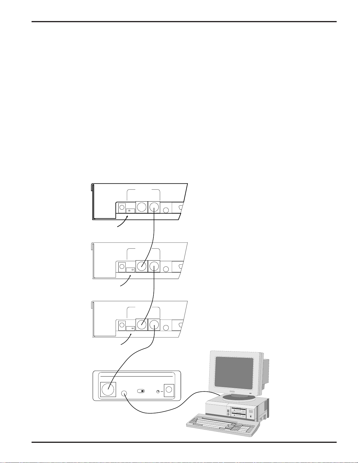
INST ALLING THE HARDW ARE
What you connect to the VI24 will depend on whether you are programming it away from its intended application or
programming it where it will actually be used.
REQUIRED CONNECTIONS
To set up the VI24, the unit must be powered on with the PC port connector attached to an available COM port on the
PC. (See the SERIAL PORT HARD WARE AND SOFTWARE section for details on wiring your own serial cable.) The
PC must have the VI24 software installed.
To use the VI24, it must be powered on with the LecNet expansion connector attached to an AM8 or AM16 Mixer, and
the Logic Outputs connected to the video switcher or other device(s) being controlled.
OPTIONAL CONNECTIONS
When setting up the VI24, it can be helpful to ha v e the LecNet expansion port connected. That way, the VI24 software
can detect the LecNet addresses and types of the mixers for you, and you can fine-tune your setup by actually
speaking into the microphones and watching the display.
When using the VI24, it ma y be desir able to have a PC connected so you can monitor the VI24’s activity.
PWR
IN
M
A
S
(CH40)
T
E
R
20 VAC
Switch in
MASTER Position
PWR
IN
M
A
S
(CH40)
T
E
R
20 VAC
Switch in
SLAVE Position
PWR
IN
M
A
S
(CH40)
T
E
R
20 VAC
Switch in
SLAVE Position
EXPANSION
S
L
A
V
OUT IN
E
EXPANSION
S
L
A
V
OUT IN
E
EXPANSION
S
L
A
V
OUT IN
E
RS232
AM8
(Master)
RS232
AM8
(Slave)
RS232
AM8
(Slave)
LECTROSONICS VI 24
EXPANSION
PC PORT
(RS-232)
VIDEO SWITCHER INTERFACE
TEST
RUN
PWR (CH40)
Rio Rancho, NM – USA
5
Page 6

SETTING UP THE VI24
Preparing the VI24 for use mostly involves using the VI24 software to describe your setup. It is then a simple matter
to transmit these settings to the VI24. If your PC is at the site where the VI24 is to be used, you can also use the
VI24 software to monitor and refine your settings.
MAIN WINDOW
The main window provides an at-a-glance
overview of the current VI24 programming
and status.
In the upper-left corner is the VI24 status
indicator. There are three values.
Live
The output pin status display is updated in
real time as the VI24 operates.
Ready
The VI24 is attached and the serial port is
open and ready for communication, but
the status does not update in real time.
Not Connected
The PC serial port is closed and no
communication with a VI24 is presently
possible.
Note: If the active window in the
Windows system belongs to an
application besides the VI24 software,
the VI24 software will disconnect from
the serial port until it again has focus.
This is intended to prevent serial port
conflicts.
The Output Pin Status display shows which of the output pins are on at any given time. This display is only valid
when receiving “Live” updates from the VI24.
At the bottom are shown the “Output Pin Assignments”. Along with each output pin is a text box describing the
signals or events that cause that output to turn on. The numbered buttons may be used to change these assignments.
The “Go Live” button tells the VI24 software you would like to dynamically monitor the status of the VI24. The VI24
software will first make sure that the settings as expressed on the PC are the same as those in the VI24. Depending
on whether you have made edits, you may be prompted to “import” the current settings from the VI24, or to “program”
the VI24 with the new settings you’ve created on the PC.
The “Quit” button exits the VI24 software. If any changes have not been saved, you
will have the chance to save them.
Most of the items on the File menu are straightforward. “New” clears the workspace to
start fresh. “Open” recalls saved settings from disk. “Save” saves the current settings
under the same name that was used to recall them. “Save As” allows the current
settings to be saved to any disk file. “Exit” works the same as the Quit button.
“Import from VI24” reads the current settings from the connected VI24 into the
workspace. Importing from the VI24 restores all settings, just as though they had
been restored from a disk file. “Program VI24” sends the current settings to the
connected VI24.
6
Page 7

Video Switcher Interface
The VI24 menu controls the current VI24 connection status. From here you may
voluntarily connect or disconnect the PC’s serial port from the VI24, as well as toggle
the “Live” display of VI24 output pin status. An option is also provided to clear all VI24
memory and return the unit to its original factory settings.
The Setup menu calls up the three main windows used for creating and changing VI24
settings. These windows are discussed below.
OPTIONS WINDOW
The VI24 Options window provides a few options to fine-tune the VI24’s behavior to
meet your specific needs.
Max. Simul. outputs, adjustable from 1 to 24, indicates how many outputs the VI24
may activate at any given time. Most video switchers can activate only one video source at a time, though some may
be able to split the screen if two inputs are active.
The Conflict Resolution option buttons tell the VI24 what to do when the number of active outputs exceeds the
maximum simultaneous outputs setting. This happens if your video switcher can accommodate only one video
source at a time, yet two or more people assigned to
different cameras speak simultaneously. Three options
are provided.
Previous pins: Active outputs remain active. The VI24
will not respond to interruptions until the original speaker
stops talking. The Pin 1 Priority option allows pin 1
activity to override a previously active pin, even though
all pins remain immune to interruptions from other than
pin 1. In this way, a discussion leader can activate the
camera, but other speakers interrupting each other will
not cause camera switches.
Lowest numbered pins: Lower numbered pins take
priority. Discussion leaders can activate the camera even
if others are still speaking.
Overview pin: The overview pin takes over. This avoids viewer fatigue by showing the entire room when many
people speak at once. The overview pin will also activate during silence unless the Overview Pin During Silence box
is unchecked.
The Hold Last Mic During Silence feature is useful when no overview camera is available. In this mode, the most
recently active output pin remains active indefinitely until another output pin becomes active. The most recent
speaker remains on camera until someone else speaks. Note that if both Hold Last Mic During Silence and Overview Pin During Silence are checked, two pins will be activated during silence, even if Max. simul. outputs is set to 1.
The Overview Pin During Silence checkbox causes the overview pin to be activated during periods of silence.
Ordinarily this box is checked. Unchecking this box permits the overview pin to be used exclusively for conflict
resolution, if desired. (See Conflict Resolution, above.)
The GPI Contact Closure frame lets you indicate what type of GPI inputs your video switcher has. Some require
momentary closure while others require continuous contact.
Time to Qualify is the length of time a mixer input must be active before the VI24 will assert the corresponding
output pin. Time to Release is the length of time a mixer input must be inactive before the VI24 will extinguish the
corresponding output pin. For both settings, 0 means no delay. Fractional seconds are permitted, but precision
beyond .5 seconds is not assured.
Rio Rancho, NM – USA
7
Page 8
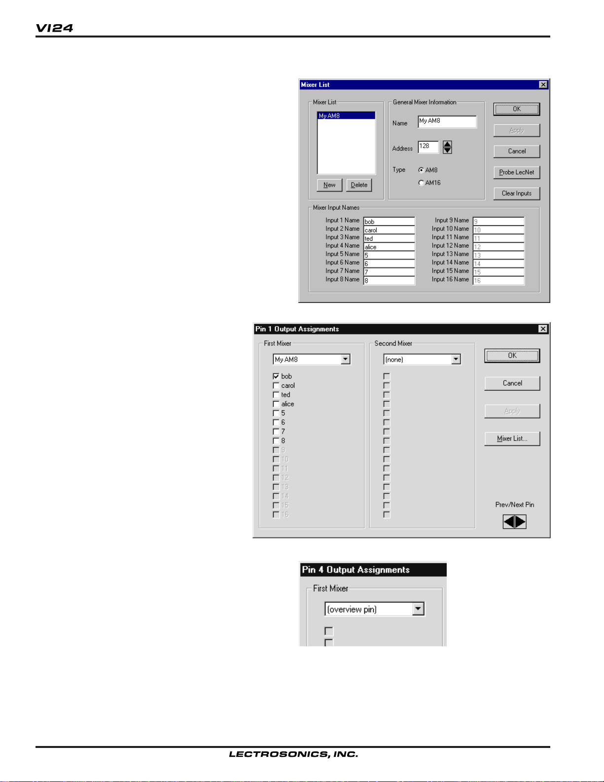
MIXER LIST WINDO W
The Mixer List provides information about your LecNet
setup. Here, you may list up to eight AM8 or AM16
mixers to be monitored by the VI24. Each mixer and
each mixer input may be named, for convenience and
ease of use. It is recommended that you name the
mixers so you may easily identify them, and that you
name the mixer inputs after the person or item associated with the microphone.
If your LecNet setup is connected, you may use the
“Probe LecNet” button to detect up to eight mixers. You
will probably still want to assign your own names to the
mixers and inputs, though the default names may also
be used.
The “Clear Inputs” button is a simple expedient to erase
all mixer input names.
PIN ASSIGNMENTS WINDOW
The Pin Assignments Window lets you assign
mixer inputs, alone or in groups, to the VI24’s
24 logic outputs. Only one logic output’s
information is shown at any one time, but the
scrolling arrows in the bottom right corner may
be used, as well as the numbered buttons or
Pin Assignments submenu in the main window, to move among the pins.
Each pin may be associated with any of the
inputs of up to two mixers, as shown. If more
elaborate configurations are needed (i.e. more
than two mixers on a single pin), multiple
output pins may be shorted together. The
output is then asserted if either pin’s conditions are met.
The Overview Pin
Any one pin may also be designated as the “overview
pin”. The intended purpose of the overview pin is to
reduce viewer fatigue by activating an overview camera
(showing the entire room) in situations where no other
camera selection would be appropriate. The overview
pin is not associated with any mixer inputs and is asserted either during periods of inactivity or during
periods of excessive activity (conflicts). The Pin Assignments window is used to choose an overview pin, but the
Options window determines under what circumstances
the overview pin is active.
8
Page 9

Video Switcher Interface
SETTING UP THE VI24 FOR THE FIRST TIME
While the VI24 software is not difficult to use, the large number of features and options might cause it to appear
intimidating at first. With that in mind, let us configure the VI24 for a simple, yet typical application, step by step.
PREPARATION
In order to follow this example, you will need the VI24
software installed and running on your PC. It is strongly
recommended, but not absolutely required, that you have
your VI24 powered on and connected to the PC. If you
have an AM8 or AM16 mixer available, connecting that
will make more options available and also make for some
enjoyable experimenting once the VI24 is configured.
1. [Follow this step only if you plan to work with the VI24
connected.] Be sure the VI24 is connected, po wered
on, and the Test/Run switch is set to “Run”. The led
should glow steadily. (If the led flashes for a few
seconds and then glows steadily, this is normal. The
unit has never been po wered on before and it is
clearing its memory.)
2. Start the VI24 software. If the VI24 is not connected,
you will need to confirm a message that says the VI24
was not found, b ut y ou can w ork offline. If the VI24 is
connected, its current settings will be imported. In
either case, you should arrive at the main windo w. If
your VI24 is connected, b ut the softw are does not see
it, please consult the TR OUBLESHOOTING section.
Note that the VI24 Status indicator will sho w not
connected if you are working offline.
3. Select “Mixer List...” from the Setup menu.
4. If you’re working with the VI24 connected, you can now
click the “Probe LecNet” button to detect your mixer(s)
and populate the mixer list dialog automatically. You
may wish to use more descriptive names than the
probe supplies (just change them). If you’re working
offline, simply enter the information as shown. Click
OK when done.
5. From the VI24 menu, select “Options...” to bring up the
Options window . Duplicate the settings shown. This
will cause the VI24 to respond immediately to changes
in mixer inputs, thus eliminating the confusion that a
delayed response can cause at first. We are also
specifying that the “overview pin” (and not the last
active mic) shall be active during silence. Finally,
we’re placing no restrictions on the number of outputs
that can be active at once. Click OK when done.
Rio Rancho, NM – USA
9
Page 10

6. On the main window, click numbered button
“1” to change the pin assignments for logic
output pin number 1. Make the settings as
shown.
7. Use the “Prev/Next Pin” spin control in the
bottom right-hand corner of the window to
advance to Pin 2’s assignments, select the
mixer in the drop-down list the same way, but
check only “carol”.
8. Use the “Prev/Next Pin” spin control to advance to Pin 3’s assignments, assign the
same mixer, but this time check both “ted” and
“alice”. (We’re pretending that those two
speakers have their own microphones but
share a camera, a common situation.)
9. Use the “Prev/Next Pin” spin control to advance to Pin 4’s assignments, and assign pin
4 as the “overview pin” by selecting “overview
pin” in the drop-down list.
Click OK when done.
10. The main screen, which shows an overview of the current settings, should
now look like this.
This display is telling us that the VI24 is connected (if you are working
offline, you’ll see the “not connected” status
instead), and that four output pins have
been assigned a function. The first pin is
assigned to Bob’s microphone alone, the
second to Carol’s, the third is shared between Ted and Alice, and the fourth is the
“overview pin”, becoming active when no
assigned input is active.
If anything looks incorrect, you can harmlessly repeat any previous step.
11. Save your work. From the File menu, click
“Save As...” and choose a name for your file.
You will now be able to recall these settings
at any time.
12. If you have been working offline, you’re now
finished until you can get your settings into
the VI24. Use the Quit button or the “Exit”
from the File menu to quit the VI24 software.
Once the VI24 is available, you can restore
your settings by running the VI24 software
and using “Open” from the File menu to read
the file you previously saved.
13. Click “Go Live”. You will be asked if you wish to update the VI24 with your new settings. Select “Yes”. A
progress indicator is displayed while the information is being transferred to the VI24. If you can see the VI24’s
led, you will notice that it flickers during programming. This is normal and is intended to indicate that the unit is
talking to the PC. The VI24 Status will now show that you are “Live”.
10
Page 11

Video Switcher Interface
14. If you have a mixer connected, you should now tap on the microphones, or manipulate the Direct/Auto switches,
to observe the behavior of the VI24. You should notice that input 1 lights up output 1, input 2 lights up output 2,
and either of inputs 3 or 4 lights up output 3. Output 4 is active whenever inputs 1 thru 4 are dead. It’s just as
you programmed it!
15. Congratulations! You have successfully set up your VI24. Setting it up for a more sophisticated scenario is really
not very different, so you can now consider yourself an experienced VI24 user.
TROUBLESHOOTING
The following are just general guidelines and initial suggestions. If a problem persists, please refer to the section,
SERVICE AND REPAIR.
PROBLEM POSSIBLE SOLUTION
No activity from led when power is applied. Ensure that the power supply is working. Ensure that power is
getting to the CH-40 (e.g. chec k f or switched or defectiv e outlets). If
another CH-40 power supply is av ailable, try it.
VI24 software can’t find the VI24. Be sure the VI24 is po w ered on, the test/run s witch is set to “run”,
and the PC Port jack is connected to an av ailable COM port on the
PC. Some devices such as internal modems take ov er the use of a
COM port while the connector on the back of the PC still appears
availab le . If a gender changer, adapter or cable extension was
used, ensure that all pins are connected normally and not in a “null
modem” configuration.
Non-VI24 LecNet software can’t see
attached LecNet devices. In order to do its job, the VI24 has to keep the PC Port disconnected
from the LecNet during normal operation. Special commands can
be sent to the VI24 to get it to stop monitoring mix ers and link the
LecNet to the PC, as well as to break the link and resume normal
operation. Both LecNet Master Pro and the VI24 software are
aware of this behavior. Howev er, if you use software associated
with other LecNet devices directly, without going through LecNet
Master Pro, problems can arise . To check for this, start the VI24
software (the VI24 should appear “connected”) and minimize the
window. This will cause the VI24 to link the PC port to the LecNet,
and then close the serial port so your other LecNet software can
operate.
VI24 or VI24 software cannot see all mix ers. Check the order in which the expansion ports are connected, as
well as the settings of the master/slave switches on all the mixers.
See the diagram in the INSTALLING THE HARDWARE section for
details on the proper configuration. Also use the LecNet softw are to
ensure that each connected LecNet device has a unique address.
ACCESSORIES
Part Number Description
CH40 Power supply
21551 LecNet expansion cable f or connection to mixers
LNETWIN LecNet software on disk
21529 Serial cable to connect the LI24 to a PC
Rio Rancho, NM – USA
11
Page 12

SERIAL CABLE WIRING DIAGRAM
The serial port on the LecNet device is a minimal RS-232 implementation. The figure shows the wiring diagram to
accommodate interconnection with either a 9 or a 25 pin serial port on a PC or other serial device.
S
R
T
Tip
Ring
Sleeve
LecNet to PC Connections
3.5MM
Stereo Plug D-Subminiature
Wiring Diagram, 9 Pin D-Sub
LecNet Device Transmit
LecNet Device Receive
Gnd
*10k
optional
LecNet Port
Wiring Diagram, 25 Pin D-Sub
9 or 25 Pin Female
CD
N/C
RX
TX
DTR
Gnd
DSR
RTS
CTS
N/C
RI
1
2
3
4
5
6
7
8
9
Host
Serial
Port
(PC)
S
R
3.5MM
T
Stereo Plug D-Subminiature
Tip
Ring
Sleeve
LecNet to AMX Connection
LecNet Device Transmit
LecNet Device Receive
Gnd
LecNet Port
9 Pin Female
N/C
RXD
TXD
N/C
Gnd
N/C
N/C
N/C
N/C
1
2
3
4
5
6
7
8
9
AMX
Port
Tip
Ring
Sleeve
LecNet Device Transmit
LecNet Device Receive
Gnd
LecNet Port
*10k
optional
RX
TX
Sig Gnd
Chassis Gnd
RTS
CTS
DSR
DTR
3
2
7
1
4
5
6
20
Host
Serial
Port
(PC)
AMX Programming Notes
If you are using an AMX system to control your
LecNet equipment, you’ll want to purchase the
Lectrosonics PT3 Protocol Translator. The PT3
connects between the AMX bus and any LecNet
equipment. With the PT3, the LecNet equipment
looks just like native AMX equipment. The PT3 is
the fastest and most productive way to control
LecNet devices with an AMX system.
12
Page 13

Video Switcher Interface
SERIAL PORT COMMANDS AVAILABLE
All LecNet devices use a modification of the typical one-to-one connection between two RS-232 compatible devices.
LecNet devices have both an RS-232 transmitter and receiver section. The transmitter section is “tri-stated”, or
placed in a high impedance mode, until the particular device is addressed. To facilitate the simple parallel connection
of multiple devices on a single RS-232 port, an addressing scheme is employed to route commands from the host to
the proper LecNet device. When a device receives its address from the host computer, it temporarily turns on its RS232 transmitter long enough to send whatever data is requested by the host. In this way, multiple devices may drive a
single transmit signal back to the host, because only the addressed device will turn on its transmitter.
Valid address values are 128-254 (80 hex-FE hex). The VI24 is a special case and always occupies address 255 (FF
hex). Because a LecNet device will interpret any single data byte whose value is greater than 127 as an address,
single byte data (as opposed to addresses) sent from the host must be in the range of 0-127. If a data value needs to
be sent from the host that exceeds 127, the host must format two bytes of output such that the first byte is the lower
7 bits of the 8 bit value, and the second byte is 1 if the MSB of the data byte is 1, or 0 if the MSB of the data byte is
0.
All interchange of commands and data with any LecNet device should be done in hex rather than ASCII. The only
exception to this is the return data on the Get Device Name command (see command description below). Each
LecNet command must be preceded by the address of the device to be controlled. If a device with the requested
address exists on the system, it will respond by sending a 0 (0 hex, not ASCII) back to the host. Thus, each interchange with a LecNet device follows this pattern:
1) Host sends device address in hex (1 byte);
2) Host receives byte of 0 hex from the LecNet device as acknowledgment;
3) Host sends command (1 byte, hex) to the LecNet device;
4) Host and LecNet device exchange data based on particular command sent.
Note that some LecNet commands cause LecNet devices to return an additional acknowledgment byte of data to
confirm the end of a transaction. This is most typical of commands that cause the LecNet device to be busy for more
than a few milliseconds processing the command. The additional acknowledgment byte lets the host know that the
LecNet device is no longer busy and can receive more commands. If a command does return an additional acknowledgment byte, this will be explicitly stated in the command description.
As an example of a specific interchange between a host and a VI24 the following general procedure would be used
to get a name string back from the VI24:
Set up the communications parameters of the device which will be the host. The correct parameters for all LecNet
devices are 9600 baud, no parity, 8 data bits, 1 stop bit. This must only be done once when the host is initialized.
1) Host sends device address 255 (1 byte).
2) Host receives byte of 0 hex from the VI24 as acknowledgment;
3) Host sends command 1 hex (1 byte) to the VI24 to get the name data;
4) The VI24 sends to the host 5 bytes. The first byte is 4 hex, which is the number of bytes in the VI24’s name
string. The VI24 will then send the ASCII characters “V”, “I”, “2” and “4” to the host.
Rio Rancho, NM – USA
13
Page 14

The following section is a listing of available VI24 commands. The word “Host” in the command descriptions means
the IBM PC or compatible, AMX controller, or Crestron controller to which the VI24 is connected.
General Device Commands
Get Device Name - Causes the VI24 to send its “name” string back. The first data byte is the length of the name
string, and the rest of the data bytes are the device name.
Host sends command - 1
Host receives data bytes: Byte 1 is the length of the name string (4 for the VI24), bytes 2 thru 5 are the
ASCII values for “VI24”.
Get Firmware Version - Causes the VI24 to send to the host the version number of the current firmware (times ten).
For example , Version 1.0 software would be returned as 10 (decimal).
Host sends command - 25
Host receives data byte: firmware version.
Get Output Status - Causes the VI24 to send the on/off status of each of its 24 output pins, packed into three bytes.
Host sends command - 20
Host receives data bytes: The byte representing output pins 1-8 is sent first, then 9-16, then 17-24. Within
each byte, the lowest-n umbered pins occupy the least significant bits. For example, in the case where output
pins 1 and 2 are on and all the rest are off, the three bytes sent would be 3, 0, 0.
Link/Unlink LecNet - Causes the VI24 to connect the PC port through to the LecNet and pause operation, or to
disconnect the PC port from the LecNet and resume operation. This allows the de vice connected to the PC
port to send commands to other devices connected to the LecNet via the VI24.
Host sends command - 40
Host sends byte - 1 for link, 0 for unlink
Host receives confirmation byte: alwa ys 0
Check Link/Unlink Status - Causes the VI24 to indicate whether the PC port is currently linked to the LecNet (and
normal VI24 operation paused) or the PC port is not linked to the LecNet (and the VI24 is operating
normally).
Host sends command - 41
Host receives data byte: 1 for link ed, 0 for not linked
14
SPECIFICATIONS
PC Port: RS-232C, 9600 baud, 8 data bits, no parity, 1 stop bit
Logic Outputs: DB-25 connector. Each output sinks to ground when the associated
conditions are met. Max. current per pin 1.5A pulse, 250mA continuous.
Power Requirements: 70 mA at 20VAC, 1.5 Watts max.
Weight: 0.5 lbs.
Dimensions: 3.25” wide, 1.25” high, 4.50” deep
Specifications subject to change without notice.
Page 15

Video Switcher Interface
SER VICE AND REPAIR
If your system malfunctions, you should attempt to correct or isolate the troub le bef ore concluding that the equipment
needs repair. Make sure you have follo w ed the setup procedure and oper ating instructions. Check out the interconnecting cords and then go through the TROUBLE SHOOTING section in the manual
We strongly recommend that you do not try to repair the equipment yourself and do not have the local repair shop
attempt anything other than the simplest repair . If the repair is more complicated than a broken wire or loose connection, send the unit to the factory for repair and service. Don’t attempt to adjust an y controls inside the units . Once set
at the factory, the various controls and trimmers do not drift with age or vibration and never require readjustment.
There are no adjustments inside that will make a malfunctioning unit start working.
LECTROSONICS’ service department is equipped and staffed to quic kly repair your equipment. In w arr anty repairs
are made at no charge in accordance with the terms of the warranty. Out of w arr anty repairs are charged at a modest
flat rate plus parts and shipping. Since it takes almost as much time and effort to determine what is wrong as it does
to make the repair , there is a charge for an exact quotation. We will be happy to quote approximate charges by phone
for out of warranty repairs .
RETURNING UNITS FOR REPAIR
You will save yourself time and trouble if y ou will follow the steps below:
A. DO NOT return equipment to the factory for repair without first contacting us by letter or b y phone . We need to
know the nature of the problem, the model number and the serial number of the equipment. We also need a phone
number where you can be reached 8 am to 4 pm (Mountain Standard Time).
B. After receiving your request, we will issue you a return authorization number (R.A.). This number will help speed
your repair through our receiving and repair departments. The return authorization number must be clearly shown on
the outside of the shipping container.
C. Pack the equipment carefully and ship to us , shipping costs prepaid. If necessary, we can provide you with the
proper packing materials. UPS is usually the best w ay to ship the units. Heavy units should be “doub le-boxed” for
safe transport.
D. We also strongly recommend that you insure the equipment, since we cannot be responsible for loss of or damage
to equipment that you ship. Of course, we insure the equipment when we ship it back to you.
Mailing address: Shipping address: Te lephones:
Lectrosonics, Inc. Lectrosonics, Inc. Regular: (505) 892-4501
PO Box 15900 581 Laser Rd. Toll Free (800) 821-1121
Rio Rancho, NM 87174 Rio Rancho, NM 87124 FAX: (505) 892-6243
USA USA
World Wide W eb: http://www.lectrosonics.com Email: sales@lectrosonics.com
Rio Rancho, NM – USA
15
Page 16

LIMITED ONE YEAR WARRANTY
LIMITED ONE YEAR WARRANTY
The equipment is warranted for one year from date of purchase against defects in
materials or workmanship provided it was purchased from an authorized dealer. This
warranty does not cover equipment which has been abused or damaged by careless
handling or shipping. This warranty does not apply to used or demonstrator equipment.
Should any defect develop, Lectrosonics, Inc. will, at our option, repair or replace any
defective parts without charge for either parts or labor. If Lectrosonics, Inc. cannot
correct the defect in your equipment, it will be replaced at no charge with a similar new
item. Lectrosonics, Inc. will pay for the cost of returning your equipment to you.
This warranty applies only to items returned to Lectrosonics, Inc., shipping costs
prepaid, within one year from the date of purchase.
This Limited Warranty is gove rn e d b y th e la w s o f th e S ta te o f New Mexico. It s ta te s the
entire liablility of Lectrosonics Inc. and the entire remedy of the purchaser for any
breach of warra n ty a s o u tline d a b o ve . N EITHER LEC T ROSONICS , INC. NOR
ANYONE INVOLVED IN THE PRODUCTION OR DELIVERY OF THE EQUIPMENT
SHALL BE LIABLE FOR ANY INDIRECT, SPECIAL, PUNITIVE, CONSEQUENTIAL,
OR INCIDENTAL DAMAGES ARISING OUT OF THE USE OR INABILITY TO USE
THIS EQUIPMENT EVEN IF LECTROSONICS, INC. HAS BEEN ADVISED OF THE
POSSIBILITY OF SUCH DAMAGES. IN NO EVENT SHALL THE LIABILITY OF
LECTROSONICS, INC. EXCEED THE PURCHASE PRICE OF ANY DEFECTIVE
EQUIPMENT.
This warranty gives you specific legal rights. You may have additional legal rights
which vary from state to state.
LECTROSONICS, INC.
581 LASER ROAD
RIO RANCHO, NM 87124 USA
January 17, 2001
 Loading...