

Page 1
Venue Receiver
Six Channel Modular Receiver
Featuring Digital Hybrid Wireless® Technology
TECHNICAL DATA
• Six-channel modular conguration
• Ratio, Antenna Phase or
Frequency diversity reception
• 256 synthesized UHF frequencies
per receiver module
• DSP-based pilot tone squelch control
• DSP emulation modes for compatibility with
analog wireless systems in addition to the
Digital Hybrid mode
• SmartNR™ noise reduction modes
• LecNet2 software interface included
• LCD interface for setup and monitoring
• USB and RS-232 computer interface
Digital Hybrid Wireless
that combines digital audio with an analog FM radio
link to provide both outstanding audio quality and
exemplary, noise-free RF performance.
Using a patented algorithm to encode 24-bit digital
audio information in the transmitter into an analog
format, the encoded signal is then transmitted over an
analog FM wireless link.
®
is a revolutionary design
The Venue Receiver is a modular solution that effectively
deals with a congested RF spectrum with a variety of
options that allows a system configuration to be idealized
for a particular installation or application.
The receiver is comprised of several components:
• The master rack mount host assembly
• Up to six receiver modules
• Built-in antenna multicoupler with loop-thru output
• LecNet2 software for setup and control
Flexibility is the core concept of the design. The receiver
modules can be operated separately, each with switched
diversity reception for a total of six audio channels, or
operated in pairs for more robust diversity reception with
one audio channel per module pair. Combinations can
also be used for special applications where some modules operate independently and others are paired.
The receiver modules are easy to change with no tools
required. The wideband multicoupler allows the use
of any frequency module in any position, except when
modules are paired, they must be in adjacent positions
as marked on the panel.
A major benefit of the design is the inclusion of a high
quality antenna multicoupler. The multicoupler is actually
a 1 in, 7 out splitter with six outputs for the receiver mod-
ules and an additional output as a “loop thru” for another
Venue receiver. This allows multiple Venue receivers to
operate from a single pair of antennas. Phantom power
for remote antenna amplifiers is available from the multicoupler antenna inputs using internal jumpers.
At the receiver, the signal is then decoded to restore
the original digital audio. This process eliminates
compandor artifacts and produces an audio
frequency response at to 20 kHz.
(US Patent 7,225,135)
Rio Rancho, NM, USA
www.lectrosonics.com
Page 2
Front Panel
The front panel provides an easy-to-use LCD interface
for setup, and provisions for quick monitoring to assist
in troubleshooting. In normal operation, the LCD shows
RF and audio levels, diversity status, pilot tone status
(where applicable) and transmitter battery status for all
six receivers at the same time.
Rear Panel
The rear panel provides six balanced audio outputs on
standard XLR connectors, 50 ohm BNC antenna inputs,
50 ohm BNC antenna outputs from the built in zero-gain
multicoupler, power jack with a locking connector, USB
port and RS-232 serial port for the computer interface.
Individual screens for each receiver are also available
at the touch of a button to provide additional information
and setup adjustments.
A headphone jack and level control is provided for indi-
vidual channel monitoring.
The receiver assembly is powered from an external
source at 10 to 18 volts DC through a locking connec-
tor, allowing the unit to operate from a wide variety of
sources in stage, studio and mobile applications.
Receiver Modules
Two modules are available to further customize the
configuration for specific applications. The VRS standard
module has xed front-end lters that cover its 25.5 MHz
tuning range. The higher selectivity VRT module has
tracking front-end lters that retune as the frequency is
changed to stay centered over the selected frequency.
The modules are a triple conversion, frequency synthesized design, controlled by the microprocessor in the
host assembly. A common DSP in the host assembly is
used for all six receiver modules to decode the received
signals and restore the digital audio. Using a single DSP
results in a significant reduction in cost per channel.
The host assembly will handle up to six receiver modules
via multi-pin connectors on the side of the main housing. The modules are held in place with snap-in retaining
clips. The clips hold the modules firmly but are easy to
remove without tools to make needed changes.
Page 3
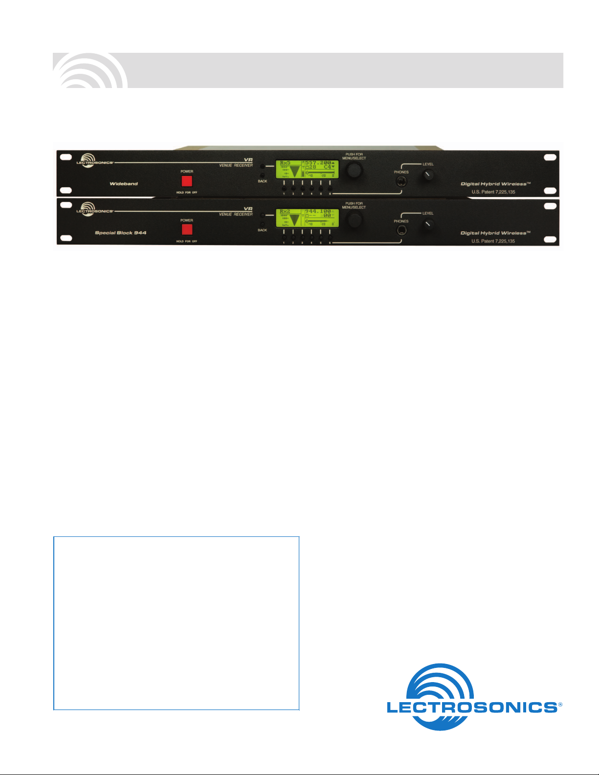
Built-in Antenna Multicoupler
An tenn a An tenn a
Every Venue receiver has a built-in multicoupler that
utilizes high current RF ampliers and a Wilkinson type
splitter for even signal distribution and high isolation between receiver modules. Optimally matched levels allow
multiple receivers to be stacked and share a single pair
of antennas - a signicant savings in space and cost in
multi-channel systems.
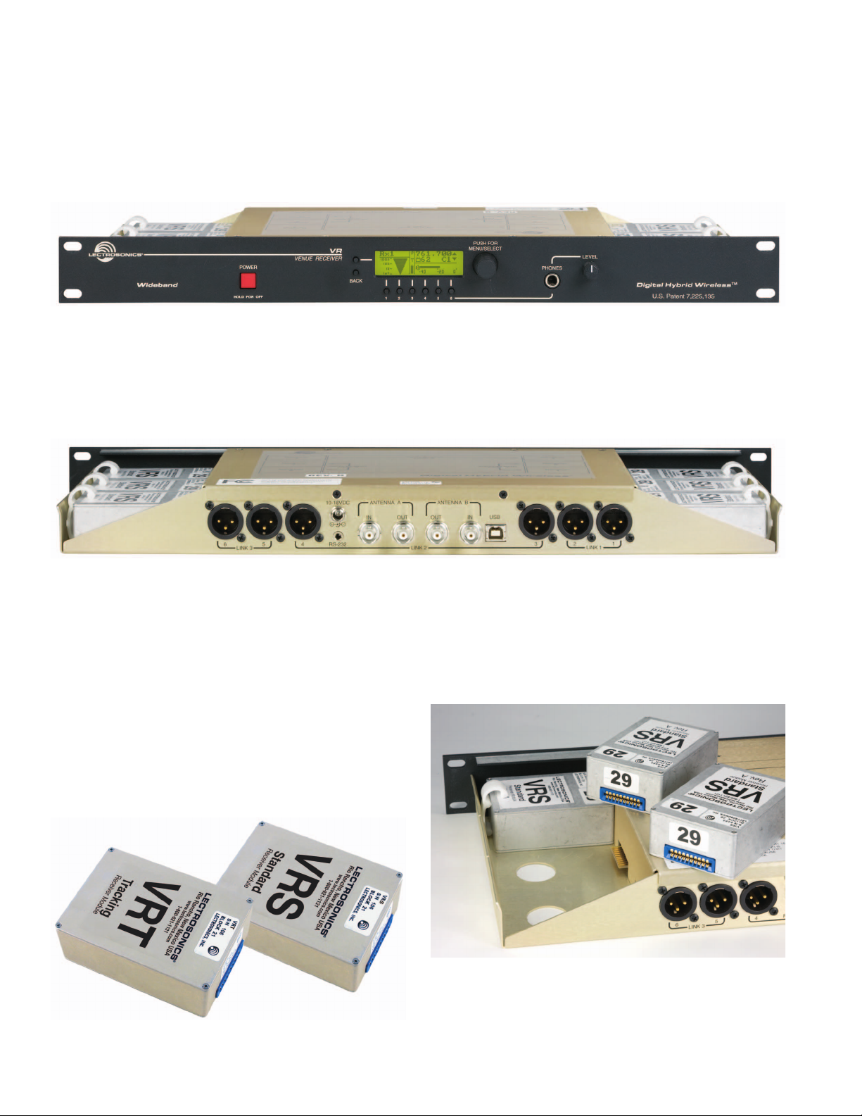
Phantom Power Jumpers
A remote amplifier can be powered directly from the
Venue receiver through the coaxial cable. The ALP650
combines a broadband LPDA antenna with an ampli-
fier, which is especially useful with the broad bandwidth
of the Venue multicoupler. Jumpers are provided on the
circuit board to enable and disable the phantom power.
The top cover is removed with six screws and the jumpers are set as shown to enable the DC power.
10.5-18VDC
2
2
2
1
1
1
3
3
3
5
6
4
LINK 3
2
1
3
6
2
1
3
6
LINK 3
RS-232
10.5-18VDC
2
2
1
1
3
3
5
4
RS-232
LINK 3
10.5-18VDC
2
2
1
1
3
3
5
4
RS-232
ANTENNA A
ANTENNA A
ANTENNA A
ANTENNA B
IN USBIN
OUT
OUT
LINK 2
ANTENNA B
IN USBIN
OUT
OUT
LINK 2
ANTENNA B
IN USBIN
OUT
OUT
LINK 2
2 1
1
3
321
2 1
1
3
321
2 1
1
3
321
2
2
1
3
3
LINK 1
2
2
1
3
3
LINK 1
2
2
1
3
3
LINK 1
The built-in multi-coupler includes “loop through” outputs for
stacking multiple Venue receivers.
Four versions are available for different applications:
• Wideband High (665 - 862 MHz)
(used outside the USA)
• Wideband Mid (537 - 768 MHz)
• Wideband Low (470 - 691 MHz)
• Special Block 944 (944 - 952 MHz
(for licensed broadcasting use)
UFM230 UFM230
Long coax cabl e Long coax cabl e
DC Power to UFM230 DC Power to UFM230
VRM
Jumpers set
towards the center
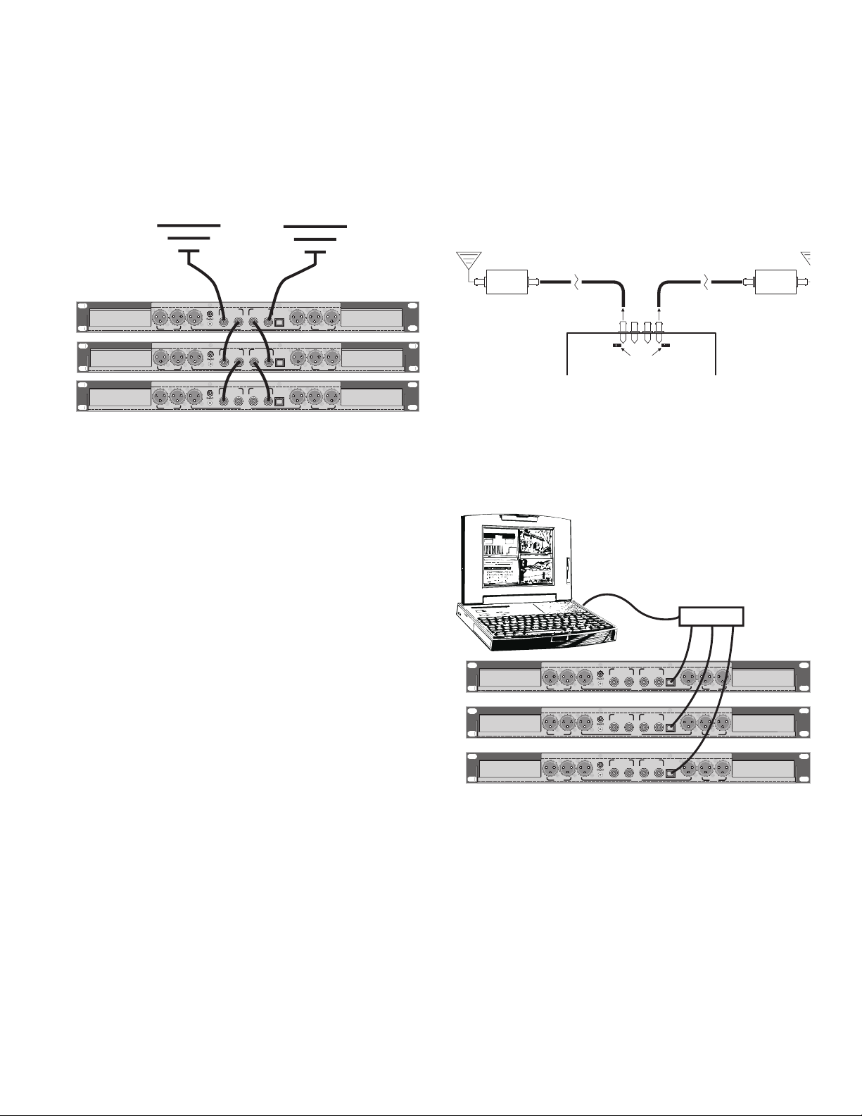
Computer Connections
The Venue receiver is typically connected to a computer
via the USB port. Multiple receivers can be connected
to a single computer using a USB hub. The receiver also
provides an RS-232 port.
USB Hub
10.5-18VDC
2
2
2
1
1
1
3
3
3
5
6
4
RS-232
LINK 3
ANTENNA A
ANTENNA B
IN USBIN
OUT
OUT
LINK 2
2 1
1
3
321
2
2
1
3
3
LINK 1
10.5-18VDC
2
2
2
1
1
1
3
3
3
5
6
4
RS-232
LINK 3
10.5-18VDC
2
2
2
1
1
1
3
3
3
5
6
4
RS-232
LINK 3
ANTENNA A
ANTENNA A
ANTENNA B
IN USBIN
OUT
OUT
LINK 2
ANTENNA B
IN USBIN
OUT
OUT
LINK 2
2 1
1
3
321
2 1
1
3
321
2
2
1
3
3
LINK 1
2
2
1
3
3
LINK 1
Page 4

SmartTune
An automated scanning process is also available that
tunes a receiver module across its tuning range and
selects a frequency with the least RF energy.
The process takes less than 30 seconds and the screen
prompts the operator to turn on a transmitter for the last
frequency selected before continuing. Once the transmitter is turned on, the process continues, prompting the
operator to continue and select the next receiver to tune.
™
Setup and Control with the LCD
Setup options and adjustments can be made via the
front panel LCD interface. Six channel select switches,
two selection and navigation switches and a push button
rotary encoder control are used with the LCD for setup.
The LCD provides a variety of displays, plus an overview
display showing transmitter battery status, RF and audio
levels, pilot tone status and diversity switching activity
for all six receivers. When receivers are paired for ratio
or frequency diversity, the two channels are grouped as
such in the overview display.
As the receiver is tuned to each frequency, the analysis evaluates RF energy within the channel as well as
energy above and below the channel to avoid selecting a
frequency adjacent to a high powered signal.
Compatibility Modes
The Venue receiver can be used to monitor IFB trans-
mitter signals by switching one or more of the receiver
modules to the IFB compatibility mode. Special DSP algorithms emulate the compandor in the IFB system and
respond to the pilot tone signal from the transmitter to
operate the receiver’s squelch. In this mode, the Venue
receiver behaves as though it is a native IFB receiver.
The IFB mode is useful for monitoring crew communica-
tions and for diagnostics. The spectrum scanning analyzer in the Venue can be used to find clear frequencies for
the IFB system, followed by listening to the IFB transmit-
ter to verify the setup.
The pilot tone frequencies in the IFB mode are different
than the Digital Hybrid mode to preserve squelch reli-
ability on both systems.
Other compatibility modes are also provided for use with
analog Lectrosonics transmitters and several models
from other manufacturers.
Pressing one of the receiver select buttons under the
LCD switches to a detail screen for that module.
The scanning spectrum analyzer can also be run from
the LCD, with manual or automatic location of clear oper-
ating frequencies. Scanning can be done with any of the
modules to locate clear operating frequencies.
A variety of menus are available for all operating parameters. The menu items and adjustments are selected with
the rotary encoder knob.
Page 5

Setup and Control with LecNet2 Software
LecNet2 is a software interface for the Venue receiver
that enables computerized setup, control and monitoring.
The software will connect through USB or RS-232 ports
on the computer and runs under Windows® 2000, XP or
Vista operating systems.*
The main window in the software displays all six receiver
modules installed in the assembly at the same time. The
display includes frequency information, and audio and
RF Levels are displayed real-time.
Right click tor
receiver setup
and other
functions
Right click the receiver pane to access individual module
setup screens and other functions. The Setup Screen for
one module allows full configuration of all settings.
RF Spectrum Analyzer
Right-clicking anywhere in a Venue Receiver opens a
pop up a menu with additional functions available for the
associated Venue Receiver, including an RF spectrum
scanner and walk test recorder.
VRpanel Spectrum Scanner
The spectrum scanner provides a visual display of RF
activity within the tuning range of the system to quickly
locate clear operating frequencies. Frequency and switch
settings are displayed for the selected receiver to simplify setup of the associated transmitter.
Walk Test Recorder
This convenient feature generates a visual “strip chart”
of RF level during a walk test. Audio can be recorded
simultaneously on the computer drive as the walk test
is conducted. Mentioning transmitter locations during
the walk test makes it easy to identify potential problem
areas when the recordings are played back.
Multiple Venue receivers can be monitored and controlled at the same time.
Popular touch screen control systems can also be configured for remote control and monitoring.
*Windows® XP and Vista are registered trademarks of Microsoft Corp.
VRpanel Walk Test Recorder
Page 6

DSP-Based Pilot Tone
Pilot tone is a popular method of eliminating noise when
a receiver is turned on without a transmitter signal. In this
situation, interference can open the audio output squelch
of the receiver and deliver loud noise into the sound
system. A pilot tone is a separate signal or tone outside
of the audio passband that controls the output squelch
of the receiver. The receiver needs to detect both a valid
RF signal and the pilot tone before the squelch will open.
There are several ways to implement a pilot tone. One
common method is to generate a supersonic audio signal using a crystal. This is helpful, however, the receiver
can pick up an invalid pilot tone through multi-signal IM
(intermodulation) which can open the squelch.
The Digital Hybrid system design uses an ultrasonic
pilot tone generated by the DSP to control the receiver
squelch, with a different pilot tone frequency for each
operating frequency. This eliminates squelch problems
in multi-channel systems where a pilot tone signal can
appear in the wrong receiver via IM.
Brief delays are also employed at turn-on and turn-off to
eliminate thumps, pops or other transients that can occur
when the power is switched on or off. The DSP generat-
ed pilot tone also eliminates fragile crystals which allows
the receiver to survive shocks and mishandling much
better than older crystal-based pilot tone systems.
Diversity Modes
The modular configuration enables several types of
diversity reception for various applications. The modules
can be used individually for switched diversity reception
with each module delivering an audio output, or coupled
into pairs for more robust diversity reception where each
module pair delivers one audio channel.
Front panel
Antenna Phase Switching Diversity
Effective diversity reception can be implemented by
combining the output of two antennas to feed a single
receiver and controlling the phase of one antenna. This
approach is commonly used for battery powered receivers where available power is limited. RF signal level is
monitored continuously, and if the level falls below a
certain threshold, the phase of one antenna is switched
180 degrees. If the signal is then stronger, the phase
remains switched until the level falls below the threshold
again. If the signal is weaker after the switch, the phase
is switched back to the previous state and monitoring
continues.
SmartDiversity
This is a microprocessor controlled algorithm used in
the Digital Hybrid system to enhance a phase switch-
ing diversity process. The algorithm monitors RF level,
rate of change of RF level and audio content to determine the optimal time to switch. The phase switching is
more aggressive when the average signal level is weak,
and when the signal level falls rapidly compared to the
average level. The algorithm also applies “opportunistic
switching” to test for the best phase state during the
silence of brief pauses in speech.
Each receiver module delivers its own audio channel,
so the system can provide up to six channels per Venue
main assembly.
OptiBlend™ Ratio Diversity
This is an audio combining process that mixes the audio
outputs from two adjacent modules in a ratio controlled
by comparing the RF signal strengths in the modules.
Being a more robust type of diversity, it is normally used
for critical applications such as a live broadcast where a
dropout could have disastrous results.
Two modules are paired and tuned to the same fre-
quency to pick up a single transmitter. The mode is set
automatically as either module is switched to this mode.
As the RF level in the two receivers is compared, more
audio is mixed from the one with the stronger signal in
an electronically damped panning process. The panning
begins to take place at much higher RF levels than a
phase switching technique to anticipate dropouts long
before they threaten to produce noise in the audio signal.
Module pairs can be selected separately. For example,
two modules could be paired for ratio diversity reception
of a lead vocalist channel, while the other four modules
could be used in the switched diversity mode, each delivering one audio channel.
Frequency Diversity
This is an automated redundancy process that pairs two
adjacent receiver modules, however, the modules are
tuned to different frequencies, each picking up its own
matching transmitter. This mode provides robust diversity
reception and added protection against battery failure.
Common applications include redundant lavaliere micro-
phones for on-air talent in live broadcasts.
In this mode the microphones are positioned very close
to each other to avoid comb filtering. The outputs of the
receivers are mixed together in the same manner as the
OptiBlend™ ratio diversity process, with the mix ratio
controlled by comparing the RF levels in the modules.
Each pair of modules in this mode delivers one audio
channel in the same manner as ratio diversity.
™
Page 7

SmartNR
A unique benet of Digital Hybrid WirelessTM is a DSP-
based algorithm that address high frequency noise in the
audio. With a noise oor at -120 dBV and a frequency
response to 20 kHz, high frequency noise in the source
audio is more apparent than in conventional wireless
systems.
The Smart Noise Reduction algorithm works by at-
tenuating only those portions of the audio signal that fit
a statistical profile for randomness or “electronic hiss.”
Because it isn’t simply a sophisticated variable low pass
filter as in earlier analog designs, much greater transparency is obtained. Desired high frequency signals having
some coherence such as speech sibilance and tones are
not affected.
The algorithm has three modes, selectable from the front
panel LCD and the software GUI:
• OFF - no noise reduction is performed.
• NORMAL - the factory default setting; enough
• FULL - enough noise reduction is applied to
™
noise reduction is applied to remove most of the
hiss from the mic preamp and some of the hiss
from lavaliere microphones.
remove most of the hiss from nearly any signal
source of reasonable quality, assuming levels are
set correctly at the transmitter.
Block Diagram
The Venue receiver uses a common microprocessor and
DSP for all six receiver modules. This modular design
reduces the cost per channel significantly, and saves
rack space by combining a 7-way antenna multicoupler,
power distribution and rack mount into a single 1RU assembly for all six channels.
Inside the main assembly the encoded radio signals
picked up by the receiver modules are sent to the DSP
for decoding and restoration of the 24-bit digital audio
signals generated in the transmitters.
The microprocessor communicates with the operator
through the front panel controls, and the USB and serial
ports when connected to a computer. It also sends and
receives control signals and data from the receiver mod-
ules and the DSP.
The DSP handles the “number crunching” to restore the
digital audio from the encoded signals and communicates pilot tone status to the microprocessor. Once the
digital audio is restored, it is finally converted to analog
and delivered to the outputs, with control signals from
the microprocessor setting the output levels.
Page 8

Specifications
Operating Frequencies (MHz) for Receiver Modules:
Block 470 470.100 - 495.600
Block 19 486.400 - 511.900
Block 20 512.000 - 537.500
Block 21 537.600 - 563.100
Block 22 563.200 - 588.700
Block 23 588.800 - 607.900 and 614.100 - 614.300
Block 24 614.400 - 639.900
Block 25 640.000 - 665.500
Block 26 665.600 - 691.100
Block 27 691.200 - 716.700 (outside USA)
Block 28 716.800 - 742.300 (outside USA)
Block 29 742.400 - 767.900 (outside USA)
Block 944 (VRS only) 944.100 - 951.900
Digital latency: • 1.5 mS (receiver only - hybrid mode)
• 3.0 mS (receiver and transmitter in hybrid mode)
• 3.0 mS (receiver only - analog compatibility mode)
The 3.0 mS latency in analog compatiblity mode time aligns the audio from analog and
hybrid transmitters when they are used together in a Venue system.
Frequency selection: 256 frequencies in 100 kHz steps per
25.5 MHz frequency block
Channel Spacing: 100 kHz
Dual Block Range: Built in antenna mulitcoupler covers a two block
range.
Pilot tone: 25 to 32 kHz; 5kHz deviation; unique
pilot tone frequency for each selected
carrier frequency (Hybrid mode)
Deviation: ± 75 kHz (max) (Hybrid mode)
Receiver Type: Triple conversion superheterodyne
Frequency Stability: ±0.001 %
Multicoupler Bandwidth:
Wideband High: 665 - 862 MHz
Wideband Mid: 537 - 768 MHz
Wideband Low: 470 - 691 MHz
Special Block 944: 8 MHz; 944 - 952 MHz
Front End Bandwidth:
VRS Module: 30 MHz @ -3 dB
VRT Module: 11 MHz @ -3 dB
Sensitivity (20 dB Sinad): 0.9 uV
AM Rejection: >60 dB, 2 uV to 1 Volt
Image and Spurious
Rejection: 85 dB
Third Order Intercept: VRS:+0 dBm, VRT: +6 dBm
Diversity Methods: Switched, ratio and frequency
FM Detector: Digital pulse counting detector @ 300 kHz
Audio Performance (overall system):
Frequency Response: 32 Hz to 20 kHz (+/-1dB), overall system
(400 Series mode)
THD: 0.2% (typical) (400 Series mode)
SNR at receiver output (dB) In Hybrid operating mode:
SmartNR No Limiting W/ Limiting
OFF
NORMAL
FULL
(Note: the dual envelope “soft” limiter provides exceptionally good handling of transients using variable attack
and release time constants. The gradual onset of limiting in the design begins below full modulation, which
reduces the measured gure for SNR without limiting by 4.5 dB).
103.5
107.0
108.5
108.5
111.5
113.0
Input Dynamic Range: 125 dB (with full transmitter limiting)
Audio Output Level: -15 dBu to +8 dBu, in 1 dB increments
LCD: 122x32 graphical display
Power Requirements: 10 to 18 VDC; 17.2 W max. (1.72 A @ 10 VDC to
1.05 A @ 18 VDC)
Weight: VRM with 6 VRS modules: 4.28 lbs. (1946 g)
VRM with 6 VRT modules: 4.45 lbs. (2018 g)
Dimensions: 19”W x 1.75”H x 7.75”D (panel to rear jacks)
(48.26 cm x 4.45 cm x 19.67 cm)
Specifications and Features subject to change without notice.
Note: Some specifications apply only when the
receiver is operating in the Digital Hybrid (400
Series) mode.
581 Laser Road NE • Rio Rancho, NM 87124 USA • www.lectrosonics.com
(505) 892-4501 • (800) 821-1121 • fax (505) 892-6243 • sales@lectrosonics.com
28 October 2010
 Loading...