

Page 1

700 Series
Encrypted Digital UHF Wireless System
INSTRUCTION MANUAL
Includes:
UDR700
UM700
UT700
Fill in for your records:
Serial Number:
Purchase Date:
Rio Rancho, NM, USA
www.lectrosonics.com
Page 2

UDR700 / UM700 / UT700
Table of Contents
Introduction ............................................................................................................................................................................................5
Overall System Design .........................................................................................................................................................................5
UDR700 Block Diagram .................................................................................................................................................................... 5
UDR700 Encrypted Digital Receiver .................................................................................................................................................... 5
Rota-Versity™ Reception ..................................................................................................................................................................5
RF Section ........................................................................................................................................................................................5
Digital Demodulator .......................................................................................................................................................................... 6
Digital Signal Processing ..................................................................................................................................................................6
Audio Output .....................................................................................................................................................................................6
UM700 Block Diagram..........................................................................................................................................................................6
Encrypted Digital Transmitters ..............................................................................................................................................................6
DSP-Cntrolled Dual Envelope Analog Limiter...................................................................................................................................6
Digital Signal Processing and Modulation ........................................................................................................................................7
Transmitter RF Output Section..........................................................................................................................................................7
Long Battery Life ............................................................................................................................................................................... 7
UT700 Block Diagram .......................................................................................................................................................................... 7
Frequency Agility .............................................................................................................................................................................. 7
Antenna ............................................................................................................................................................................................7
UT700 Microphone Element .............................................................................................................................................................7
Comparing Diversity Reception and Rota-Versity™ ........................................................................................................................... 8
SmartDiversity™ ............................................................................................................................................................................... 8
Rota-Versity™ ...................................................................................................................................................................................8
The 700 Series Encryption System ...................................................................................................................................................... 9
Level 1 ..................................................................................................................................................................................................9
Level 2 ..................................................................................................................................................................................................9
Level 3 ..................................................................................................................................................................................................9
UDR700 Controls and Functions ........................................................................................................................................................11
UDR700 Front Panel ..........................................................................................................................................................................11
RF Level Indicator ...........................................................................................................................................................................11
Transmitter Audio Level...................................................................................................................................................................11
Information and Status Display ....................................................................................................................................................... 11
Menu Button....................................................................................................................................................................................11
Select Up/Down Buttons .................................................................................................................................................................11
Rota-Versity™ Switch .....................................................................................................................................................................11
Antenna Phase Combining Indicator .............................................................................................................................................. 11
Power Switch ..................................................................................................................................................................................11
Security Jack .................................................................................................................................................................................. 11
Audio Monitor Level ........................................................................................................................................................................11
Audio Monitor Jack ......................................................................................................................................................................... 11
UDR700 Rear Panel ...........................................................................................................................................................................12
AC Power Supply ............................................................................................................................................................................12
EXT Power Connector ....................................................................................................................................................................12
Analog Audio Output Control ..........................................................................................................................................................12
GND/LIFT Switch ............................................................................................................................................................................ 12
Phase 0/180 ....................................................................................................................................................................................12
Digital Audio Output - AES-3id........................................................................................................................................................12
Antenna Jacks ................................................................................................................................................................................12
UDR700 Iinformation and Status Display Menus and Functions........................................................................................................12
Power Up Sequence ....................................................................................................................................................................... 12
Enabling and Disabling the Buttons ................................................................................................................................................ 12
Menu Interface....................................................................................................................................................................................13
Main Tuning Menu .............................................................................................................................................................................. 13
TV Tuning Menu .................................................................................................................................................................................. 13
Group Tuning Menu ............................................................................................................................................................................ 13
AES Output Menu...............................................................................................................................................................................13
Security Menu ....................................................................................................................................................................................13
Key Generation Menu .........................................................................................................................................................................13
LECTROSONICS, INC. 2
Page 3

Encrypted Digital Wireless System
UM700 Controls and Functions ..........................................................................................................................................................14
Input Jack ...........................................................................................................................................................................................14
Power On/Off Switch .......................................................................................................................................................................... 14
Power LED .......................................................................................................................................................................................... 14
Frequency Select Switches ................................................................................................................................................................14
Audio Level Control ............................................................................................................................................................................14
Modulation LEDs ................................................................................................................................................................................14
Antenna ..............................................................................................................................................................................................14
Adjustable Low Frequency Roll-Off Control ........................................................................................................................................ 15
The Belt Clip .......................................................................................................................................................................................15
UM700 Battery Installation ................................................................................................................................................................. 15
UT700 Controls and Functions ...........................................................................................................................................................16
Power On/Off Switch .......................................................................................................................................................................... 16
Power LED .......................................................................................................................................................................................... 16
Hiding the Power LED ........................................................................................................................................................................16
Encryption Key Link ............................................................................................................................................................................ 16
Frequency Select Switches ................................................................................................................................................................16
Modulation LEDs ................................................................................................................................................................................17
Audio Level Control ............................................................................................................................................................................17
Locked Mode ...................................................................................................................................................................................... 17
UT700 Battery Installation ..................................................................................................................................................................17
System Installation and Operating Instructions ............................................................................................................................... 19
System Setup .....................................................................................................................................................................................19
Changing the Security Level...............................................................................................................................................................22
Setting the Encryption Key .................................................................................................................................................................22
Protecting the Encryption Key ............................................................................................................................................................23
UT700 Vari-Mic™ Controls .................................................................................................................................................................23
Bass / Mid / Treble (LO / MID / HI) .................................................................................................................................................. 23
Preamp Level Control .........................................................................................................................................................................24
Bass Filter ..........................................................................................................................................................................................24
5-Pin Input Jack Wiring (UM700) ........................................................................................................................................................24
RF Bypassing (UM700) ......................................................................................................................................................................25
Line Level Signals (UM700) ............................................................................................................................................................... 25
Encryption Key Cables .......................................................................................................................................................................25
Troubleshooting ...................................................................................................................................................................................27
Power Problems .................................................................................................................................................................................27
UDR700 ..........................................................................................................................................................................................27
UM700 ............................................................................................................................................................................................ 27
UT700 .............................................................................................................................................................................................27
RF Problems.......................................................................................................................................................................................27
Audio Problems ..................................................................................................................................................................................28
Specifications .......................................................................................................................................................................................30
Overall System................................................................................................................................................................................30
UDR700 Digital Receiver ................................................................................................................................................................ 30
UM700 Digital Transmitter ...............................................................................................................................................................30
UT700 Digital Transmitter ................................................................................................................................................................ 30
Replacement Parts and Accessories .................................................................................................................................................32
Service and Repair ............................................................................................................................................................................... 33
Returning Units for Repair ..................................................................................................................................................................33
Microphone Cord Termination ............................................................................................................................................................34
Rio Rancho, NM 3
Page 4

UDR700 / UM700 / UT700
LECTROSONICS, INC. 4
Page 5
Introduction
X
The 700 Series encrypted digital wireless microphone
system uses a digital audio chain and an encrypted
digital RF communications link for excellent sound
quality and data security. The applications for this
system include high-end motion picture, studio and
stage, and boardrooms, courtrooms and conference
rooms where security is a concern. While these
applications are very different from one another, this
single system is able to provide significant benefits in all
of these areas of operation.
Overall System Design
The 700 Series system uses state-of-the-art techniques
to offer superb audio quality and formidable security.
Audio is sampled at 44.1 kHz using a 24-bit A/D converter in the transmitter. (For perspective, a CD uses
the same sample rate, but only 16 bits per sample.)
High-entropy encoding, cryptographically secure
encryption, efficient modulation/demodulation,
decryption and decoding all take place in the digital
domain, using highly optimized proprietary techniques.
If digital audio output is desired, there is no need to
convert back to analog at all; otherwise, the first and
only conversion back to analog occurs at the receiver’s
output.
In the transmitter, the audio first passes through a DSPcontrolled, dual-envelope analog limiter to prevent
distortion from occurring on high level peaks. The audio
is then digitized and fed to a DSP. The DSP uses a
proprietary audio encoding scheme to lower the bit rate
and provide the high entropy required for secure
encryption. The bit stream is then encrypted, apportioned into packets, and sent over the air using a
proprietary digital modulation technique.
In the receiver, the digital baseband signal is demodulated to recover the original bit clock and data stream.
Encrypted Digital Wireless System
The DSP separates out the packet headers and decrypts the audio data. The audio data is then decoded
to recover the original audio signal present in the
transmitter.
UDR700 Encrypted Digital Receiver
Rota-Versity™ Reception
The UDR700 receiver uses a proprietary technique to
implement a unique and very effective type of diversity
reception called Rota-Versity
Rota-versity is a microprocessor controlled antenna
phase matching technique. The UDR700 uses a four
way phase shifter to combine the power of the two
antennas in any of four phase angles, 90 degrees apart.
Hundreds of times per second, all of the four phase
angles are tried. The angle offering the best reception
is always used for the audio data. The result is that the
diversity system “tracks” the phase shifts between the
two antennas, keeping phase cancellation loss under 1
dB at all times. Multi-path dropouts are minimized and
operating range is maximized by using both antennas,
in phase, at all times.
RF Section
The RF section of the UDR700 is a traditional dualconversion superheterodyne receiver. Once the
antenna power is combined, the RF signal is passed
through dual tracking filters. These 7 MHz bandpass
filters are centered on the operating frequency as it is
tuned through the 25.6 MHz frequency block for excellent selectivity and interference rejection. The first
tracking filter is followed by a GaAs FET attenuator that
applies from 2 to 32 dB of attenuation to provide very
high overload protection. The amount of attenuation is
controlled by the RSSI (Received Signal Strength
Indicator) feedback from the second IF.
TM
.
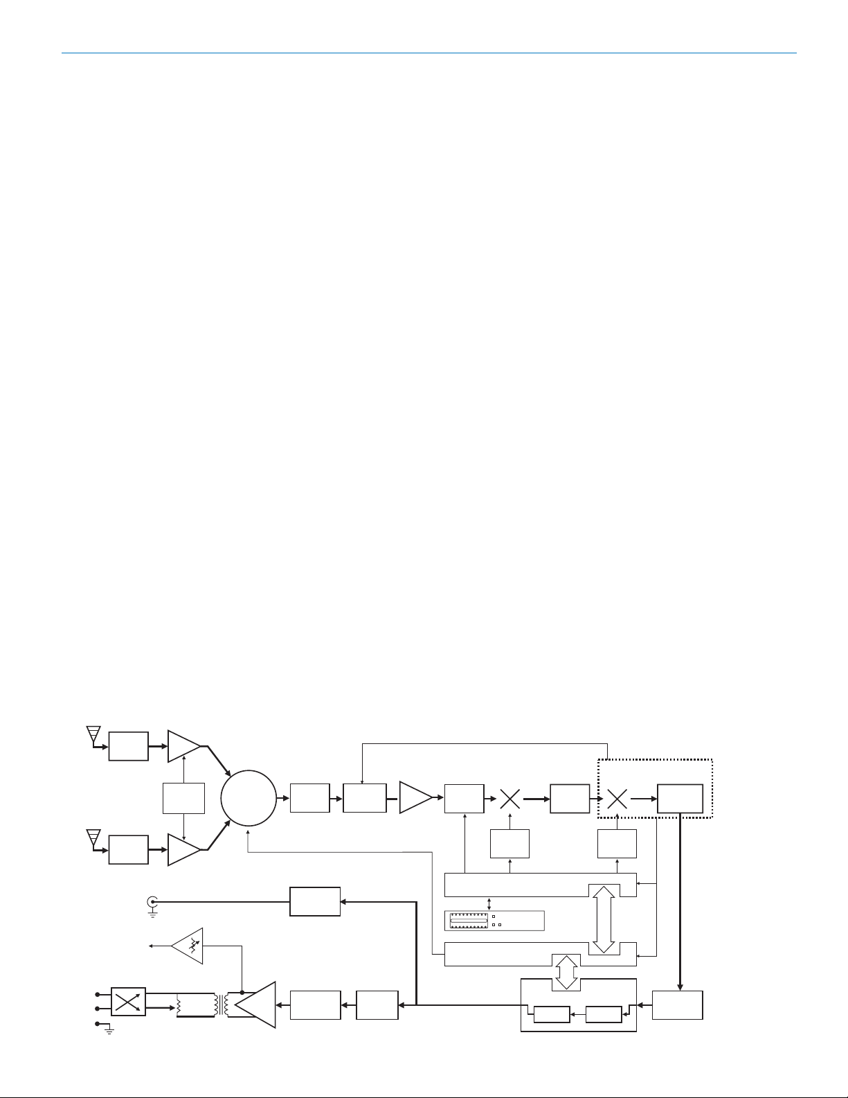
UDR700 Block Diagram
Input
Input
Bandpass
Bandpass
Filter
Filter
Input
Bandpass
Filter
AES-3id
Jack
Headphone
Out
LR
Phase
Out
Reverse
2
3
1
Rio Rancho, NM 5
RF
Amp
Antenna
Kill Switch
A/B/Rot.
RF
Amp
Attenuator
Switch
600
4-Way
Phase
Combiner
0/90/180/270
Audio
Amp
Tracking
Filter
AES3
Transmitter
Anti-aliasing
Filter
FET
Attenuator
D/A
Converter
RF
Amp
RSSI
Tracking
Filter
Oscillator
Microprocessor
Microprocessor
1st
Mixer
1st
Local
Display
& Buttons
244
MHz
Decode
Dual
SAW
Filters
2nd
Mixer
2nd
Local
Oscillator
Digital Signal
Processor
Decrypt
Integrated Circuit
10.7
MHz
Quadrature
Detector
RSSI
Digital
Demodulator
Page 6

UDR700 / UM700 / UT700
The 244 MHz from the first IF is reduced to the second
IF of 10.7 MHz, and is then fed to the Quadrature
Detector. The first mixer is a GaAs MMIC device with a
rated IP3 (third order intercept) of +24 dBm to minimize
undesired IM products. Because the signal is digital,
thermal drift in the detector has little effect on the
signal’s content, unlike an analog receiver.
Digital Demodulator
The digital demodulator consists of a PLL clock recovery circuit and a bit slicer. The recovered bit clock and
data stream are fed to the DSP. In addition, the recovered bit clock is used to derive the timings for the
receiver’s digital audio circuits, so the receiver audio is
synchronous with the transmitter audio, sample for
sample.
Digital Signal Processing
The DSP uses the packet headers as a timing reference to recover the digital audio data. The data is then
decrypted and decoded to recover the original digitized
audio samples. Additionally, the packet headers also
contain transmitter battery status information, which is
extracted by the DSP.
Audio Output
The digital audio samples are sent to the AES-3id
transmitter for digital audio output, and to the D/A
converter for conversion to analog. The converter
output is filtered and amplified, and then fed to a
transformer, attenuator and XLR jack. The analog
output is also sent to a separate headphone amplifier
on the UCR700 front panel for monitoring purposes.
The signal at the headphone output is taken just ahead
of the output transformer, so it provides the same audio
quality as the XLR output and can also be used as a
second output or recorder feed.
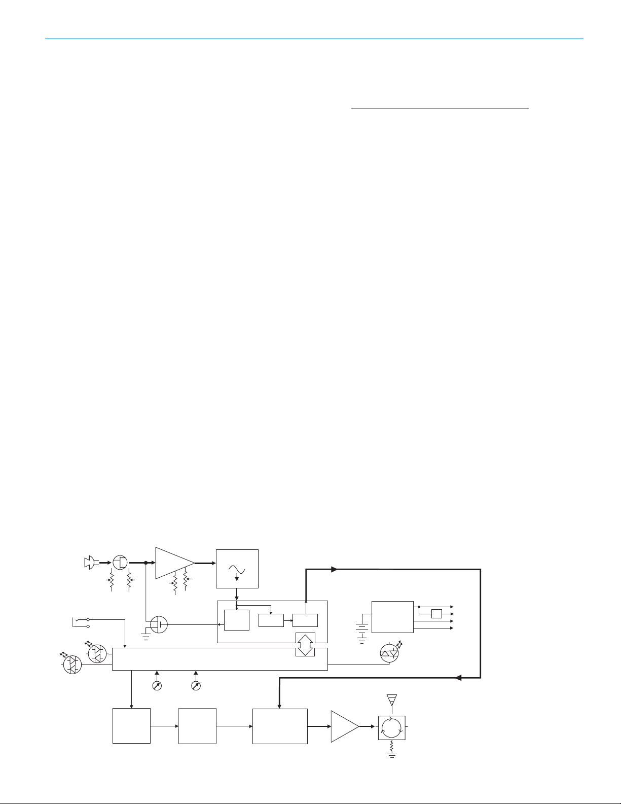
UM700 Block Diagram
Mic
Jack
1
2
3
4
5
+3.3V Bias
Supply
Encryption
Key Link
Bicolor
Modulation
LEDs
Hi/Lo
Pass
Filter
Input
Amp
LF
Rolloff
Shunt
Limiter
Freq
Switches
Audio
Audio
Level
Microprocessor
A-D
Converter
11001001
Dual
Envelope
Limiter
Digital Signal Processor
Encode
Encrypt
The main audio output amplifier is set for maximum
gain. This output passes through a passive attenuator
and phase switch on its way to the rear panel Audio
Output XLR jack. The passive attenuator reduces the
audio level in calibrated 5 dB steps, ensuring the signalto-noise ratio of the receiver remains the same at all
output levels selected by the rear panel control.
Encrypted Digital Transmitters
Two encrypted digital transmitters are offered, a belt
pack unit and a hand held unit. Although their physical
packages differ, internally, they are essentially the
same. The major difference is the microphone input
jack in the UM700 and the VariMic
hand held transmitter.
The microphone input jack used in the UM700 is
configured so that virtually every lavaliere, hand-held or
shotgun mic can be used, regardless of whether they
use positive or negative bias. (See UM700 Controls
and Functions and 5-Pin Input Jack Wiring.)
The UT700 uses a built in microphone element. (See
UT700 Microphone Element.)
DSP-Cntrolled Dual Envelope Analog Limiter
In order to make the best use of the high quality A/D
converter, microphone audio is limited in the analog
domain first, before being sampled. The DSP controls
this process, but because the limiting is done in the
analog domain, levels near the converter’s maximum
may be used without fear of clipping. (The limiter has a
range of more than 30 dB for excellent overload protection.)
The limiter has a fast attack, but different release
characteristics, depending on the nature of the signal
that drove the input into limiting. Brief transients result
in a fast decay, to avoid “pumping” effects, while sustained loud signals result in a slower decay, to keep
distortion to a minimum. The result is a transparentsounding limiter with excellent low distortion characteristics.
Switching
Power
9V
Battery
Supply
Bicolor
Power
LED
+3.3v
+1.8v
+9v
-3v
™
used in the UT700
Phase
Locked
Loop
Voltage
Controlled
Oscillator
Digital
Modulator
RF
Amp
50
Isolator
LECTROSONICS, INC. 6
Page 7
Encrypted Digital Wireless System
Digital Signal Processing and Modulation
The preamplified and limited audio signal is converted
to digital using a 24-bit A/D converter and fed to the
DSP. Within the DSP, the audio is encoded to reduce
the bit rate and increase entropy in the data stream
prior to encryption. The data stream is then encrypted
and apportioned into packets, delimited by packet
headers. The complete bit stream is modulated onto
the carrier using a modified pi/4 DQPSK (differential
quadrature phase shift keying) method. This modulation method makes efficient use of the RF spectrum
and is easy to demodulate reliably.
Transmitter RF Output Section
Intermodulation (IM) is a problem that occurs in the final
amplifier stages of conventional transmitters when the
transmitters are within a few feet of each other. This
can create serious problems in multichannel wireless
systems when an IM signal falls in the same range as
the carriers, IF frequencies, local oscillator or image
frequencies of the systems being operated. The
UM700 and UT700 eliminate this problem by passing
the modulated radio signal through a circular isolator
before it enters the antenna. The circular isolator
functions like a “one-way check valve,” allowing the RF
signal to pass through to the antenna, but not allowing
spurious RF to pass back into the transmitter amplifier
stage. This provides excellent stability and eliminates
IM in the output stage of the transmitter.
Long Battery Life
The use of highly efficient circuits and switching power
supplies throughout the design allow over 4 hours of
operation using a single 9 volt alkaline battery. (A 9 V
lithium battery will provide over 7.5 hours of operation.)
The battery compartment is a unique mechanical
design which automatically adjusts to fit any brand of 9
volt battery, and the battery contacts are spring loaded
to prevent “rattle” as the unit is handled.
UT700 Block Diagram
Mic
Element
Preamp
Level
Encryption
Key Link
Bicolor
Modulation
LEDs
Preamp
Tone
Input
Amp
LF
Rolloff
Shunt
Limiter
Freq
Switches
Audio
Audio
Level
Microprocessor
A-D
Converter
11001001
Dual
Envelope
Limiter
Digital Signal Processor
Encode Encrypt
Frequency Agility
700 Series wireless systems are currently available in
four different “blocks” of 256 frequencies each, from
562.200 to 665.500 MHz.
Note: Frequencies between 608.000 MHz to
614.000 MHz are reserved and not available for
commercial use.
Each of these blocks is preset at the factory and
provides 256 selectable frequencies in 100 kHz steps
over a 25.6 MHz bandwidth. This wide variety of
selectable frequencies alleviates carrier interference
problems in mobile or traveling applications. Two 16position rotary switches are used to select the frequency.
The transmitter section uses a synthesized, frequency
selectable main oscillator. The frequency is extremely
stable over a wide temperature range and over time.
Antenna
At UHF, where wavelengths and antennas are shorter
than at VHF, a resonant length wire is preferred over
using the microphone cable as the antenna. The
antenna on the UM700 is a flexible 1/4 wavelength
insulated galvanized steel cable, detachable via an
SMA connector. The impedance of this connector is 50
Ohms.
The UT700 has a dipole antenna incorporated into the
circuit board.
UT700 Microphone Element
The UT700 includes the Lectrosonics VariMicTM mic
element. The VariMic
electret) microphone that is adapted for the unique
circumstances of wireless microphones. It offers
excellent dynamic range while minimizing handling
noise and low frequency noise (rumble or wind).
In the VariMic
TM
increases the usable dynamic range 12 dB and greatly
reduces distortion, just as if the FET were being
Switching
9V
Battery
Power
Supply
TM
is a cardioid condenser (back
, an unusual pumped source FET circuit
+3.3v
+1.8v
+9v
-3v
Bicolor
Power
LED
Phase
Locked
Loop
Rio Rancho, NM 7
Voltage
Controlled
Oscillator
Digital
Modulator
RF
Amp
50
Isolator
Page 8

UDR700 / UM700 / UT700
ROTA-VERSITY™ DIGITAL
PHASE CORRELATION
0
270
90
MICROPROCESSOR
RECEIVER
180
PHASE CORRECTED
COMBINING
supplied with 48 Volts. A unique 16-position sensitivity
control at the element itself can also adjust the sensitivity over a 15 dB range. This is in addition to the normal
gain control in the wireless microphone. The result is
the widest dynamic range of any condenser mic in a
wireless microphone.
TM
The VariMic
has a three-point damped rubber suspension to reduce high frequency handling noise and a
generous sized windscreen to keep wind noise and
breath pops away from the microphone.
Comparing Diversity Reception and Rota-Versity
The UDR700’s new approach to diversity reception is a
vast improvement over traditional designs. Traditional
analog diversity reception designs employed techniques
ranging from simple antenna and audio signal switching
using one or two receivers, to dual-receiver ratio
combining systems. In the digital realm, even more
advanced techniques are possible to analyze and
correct antenna phase.
A popular phrase, “true diversity,” arose in defense of
dual-receiver audio switching diversity designs versus
very low cost receivers that simply had two antennas
mounted on a single unit. Diversity reception can be
implemented by mixing or selecting the audio from two
separate receivers, or by various antenna combining
techniques ahead of the receiver. In reality, all receiver
designs can aptly be called “true diversity” if they make
use of two or more antennas that are receiving diverse
(uncorrelated) signals.
Two diversity designs found in use today include Audio
Switching Diversity and Ratio Diversity. Both offer some
improvement in
audio reception,
but with a
significant
increase in
equipment costs
because of the
need for two
receivers.
SmartDiversity
from
Lectrosonics is
different.
8
™
SmartDiversity
AUDIO SWITCHING
DIVERSITY
RECEIVER A
SWITCH
AUDIO
OUTPUT
™
RECEIVER A
RECEIVER AUDIO OUTPUT
SELECTED BY RF LEVEL
RATIO DIVERSITY
AUDIO COMBINING
RECEIVER A
AUDIO
PANNING
CIRCUIT
RECEIVER A
RECEIVER AUDIO OUTPUTS
MIXED IN OptiBlend™ RATIO
CONTROLLED BY RF LEVEL
AUDIO
OUTPUT
SmartDiversity™ is a microprocessor controlled technique that automatically analyzes audio content and RF
levels to determine optimum timing for the switching
activity. Active analog antenna phase switching techniques use both antennas at the same time, with 180
degree phase switching to help keep the received
signals in phase and minimize dropouts. When the
overall RF signal strength quickly drops, the phase of
one antenna is switched 180 degrees. If the switch
increases the RF
level, it will remain
latched in that
position until the
RF level quickly
drops again. Both
antennas are used
at the same time,
so overall operating
range is also
improved.
Rota-Versity
Rota-Versity™ is only possible in the digital realm. Rota-
TM
Versity
output of two antennas in any of four phase angles,
each 90 degrees apart, regardless of RF levels. Hundreds of times per second, all of the phase angles are
explored, with the angle offering the best reception
used for the audio data. The result is the diversity
system “tracks” the phase shift between the two antennas to ensure that they always add to one another (they
are always less than 90 degrees out of phase). Multipath dropouts are minimized and operating range is
maximized by using both antennas simultaneously.
Because it times
phase switches
to happen only
during digital
packet headers
where no audio
is being conveyed, Rota-
™
versity
transparent and
cost effective .
is also
™
ANTENNA PHASE
SWITCHING
MICROPROCESSOR
RECEIVER
180 DEGREE PHASE
SWITCHING
™
uses a four-way phase shifter to combine the
LECTROSONICS, INC.
Page 9
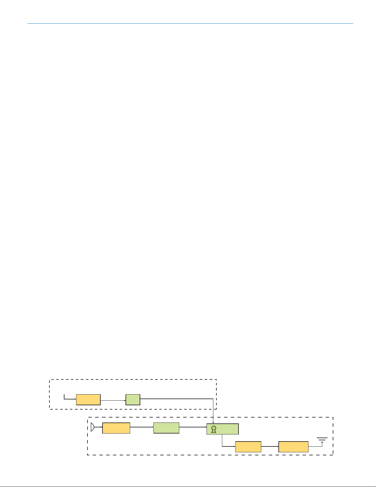
The 700 Series Encryption System
Encrypted Digital Wireless System
To guard against eavesdropping, the encryption in the 700
Series digital wireless system makes use of several
processes and a unique key setup procedure to provide a
high level of entropy and thus maximum security. A 128bit key is used to create a formidable barrier against brute
force attacks attempting to break the encryption code.
The result is 340 trillion, trillion, trillion possible key
combinations.
The audio signal entering the transmitter first passes
through a DSP controlled, dual-envelope limiter that cleanly
limit signal peaks up to 30 dB above full modulation. The
signal is then converted to 24-bit digital audio, with sampling
at 44.1 kHz. The resulting bit stream is then digitally
compressed to meet the bandwidth requirements for the
radio output, encrypted and then transmitted over the air.
The encryption key setup procedure involves a cable
connection between the transmitter and receiver. Once
connected, the receiver maybe placed into the key
generation mode and the operator is prompted to make
several button pushes on the front panel of the receiver.
These button pushes capture the instanteneous value of a
fast, free running, 16-bit timer. The captured values are
combined to create the eight, 16-bit segments of the 128bit encryption key.
With the exception of Security Level 3, any number of
transmitters can be connected during a single setup
procedure to share a common encryption key. Regardless
of which Security Level is selected, only one receiver can
share the key with the transmitter(s). This prevents the
use of a second receiver to eavesdrop on the transmitted
signal.
The 700 System offers three levels of security, trading off
ease of use for immunity to attack.
Level 1
Security Level 1 offers the most intuitive operation. Once
the key has been set, the equipment may be operated
exactly the same as a traditional analog system. The
transmitter and receiver may be powered on in any
sequence, and the transmitter may move in and out of
range without consequence (except normal squelching).
Security in this mode is excellent, but the scrambling
sequence repeats approximately every 20,000 bits,
theoretically exposing the user to differential attacks. Due
to its ease of use and quite effective security, Level 1 is the
default security level.
Level 2
Security Level 2 offers much greater encryption strength,
at the cost of slightly less intuitive operation. In Level 2,
the scrambling sequence never repeats (i.e. the PRNG is
free-running), so the receiver must be on and ready to
receive when the transmitter is first switched on. Some
signal loss is tolerated but if the transmitter should wander
out of range for more than ten seconds, it will be necessary to switch it off and on again to restart the sequence,
resynchronizing with the receiver. Security in this mode is
a great deal stronger than Level 1, since the scrambling
sequence never repeats. Only if the sequence is deliberately reused (i.e. by cycling transmitter power after
prolonged signal loss, or by reusing the same key session
after session) is a differential attack possible even in
theory.
Level 3
Security Level 3 offers the strongest encryption of all,
again at the cost of some convenience. Level 3 is much
like Level 2, except that the equipment itself enforces a
policy that
ever be used more than once
of cryptography: key reuse leads to vulnerability. Thus,
Level 3 security is about as close to the holy grail of the
one-time pad as any wireless vendor is likely to offer at a
reasonable price. Operation is a little different in Level 3:
1. The transmitter will not send any audio until a new key
2. Only one transmitter may receive each key.
3. If the transmitter is out of range of the receiver for more
All three levels offer strong encryption, so each user may
make a policy decision based on an assessment of risk.
Those requiring ease of use may relax, knowing that
eavesdropping is extremely difficult even in Level 1. Many
users may find Level 2 to be just as convenient, allowing
them to use greater encryption strength. Those users
willing to follow stricter security procedures can use Level
3, the strongest encryption available today from a wireless
microphone.
no portion of any scrambling sequence shall
. This is a fundamental tenet
is transferred from the receiver.
than ten seconds, it will be necessary to generate a
new key in order to continue using the system.
RANDOM
BUTTON
PRESSES
Rio Rancho, NM 9
ENTROPY
HARVESTER
AUDIO
INPUT
ENCRYPTION KEY CREATION PROCESSOR FROM RECEIVER
128-BIT KEY
(SEED)
24-BIT
A/D CONVERTER
PRNG
BIT STREAM
(SCRAMBLING SEQUENCE)
BIT STREAM
HIGH ENTROPY
(DIGITAL COMPRESSION)
ENCODER
BIT STREAM
ENCRYPTER
MODULATOR
DIGITAL TRANSMITTER HARDWARE
ANTENNA
OUTPUT SECTION
Page 10

UDR700 / UM700 / UT700
LECTROSONICS, INC. 10
Page 11
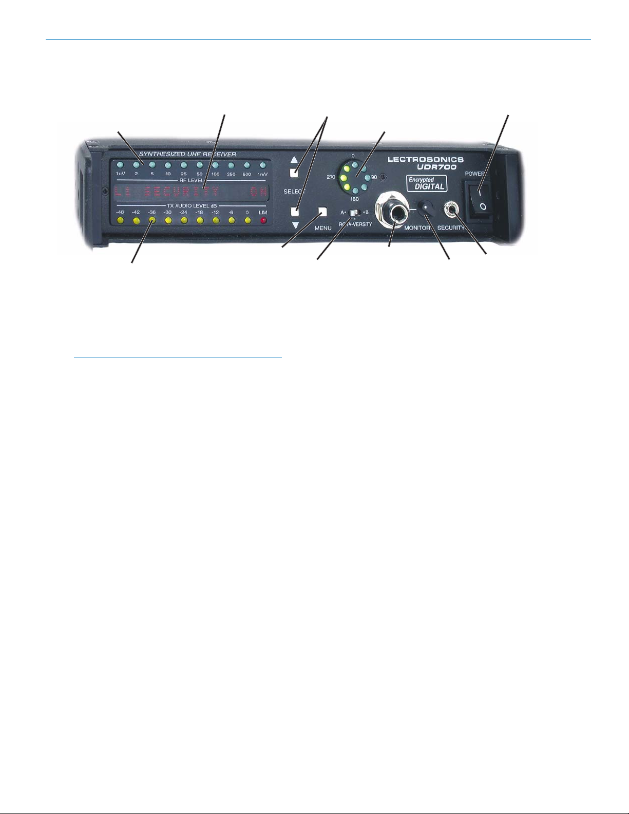
UDR700 Controls and Functions
UDR700 Front Panel
Information and Status Display SELECT Up/Down Buttons POWER On/Off Switch
RF Level Indicator
Antenna Phase Combining Indicator
Encrypted Digital Wireless System
MENU Button
Transmitter Audio Level ROTA-VERSITY Switch Audio Monitor Level Control
RF Level Indicator
A 10-segment LED strip indicates the level of the
incoming RF signal. The strip is calibrated to provide
accurate indications from 1 uV to 1 mV. The LEDs are
highly visible from a distance.
Note: A digital wireless receiver behaves differently
than an analog receiver during weak RF signal
conditions. The audio signal to noise ratio of an
analog receiver will gradually deteriorate as the RF
signal level drops, and the receiver will continue to
produce audio (accompanied by some noise) even
at very low RF levels. The signal to noise ratio of a
digital receiver remains largely unchanged as the
RF signal level drops, until suddenly, over a range
of just a few dB, the signal abruptly degrades and
then is muted altogether.
The RF Level Indicator can accurately display signals
as low as 1 uV to permit checking for interfering signals
just below the squelch threshold of the receiver. With
the transmitter turned off, the LEDs will indicate the
presence of interference.
Transmitter Audio Level
The 10-segment Transmitter Audio Level indicator strip
displays the modulation (audio level) of the incoming
signal. The strip is calibrated in 6 dB steps over an
expanded scale (54 dB) providing an extremely accurate visual “picture” of the signal dynamics.
Information and Status Display
A 16-segment Information and Status Display provides
information about the security level, selected frequency,
or tuning group, transmitter Frequency Select Switch
setting, TV channel, transmitter battery level and
system locked/unlocked status.
Audio Monitor Jack SECURITY Jack
Select Up/Down Buttons
The SELECT Up/Down buttons are used to select
various options within each display selection and for
setting the operating frequency of the receiver.
Rota-Versity™ Switch
The Rota-Versity™ switch is a three-position switch
used to either enable diversity operation, or to temporarily disable diversity operation (by selecting antenna A
or antenna B) for diagnostic purposes.
Antenna Phase Combining Indicator
Indicates the phase relationship between antenna A
and right for antenna B. Also provides a visual warning
if the Rota-Versity switch is not in the normal (centered)
position, or if one of the antennas is malfunctioning.
Power Switch
The Power switch applies AC or External DC power to
the unit. This switch, in conjunction with the MENU
button, can also be used to lock, or unlock the front
panel buttons (see Disabling Front Panel Buttons), and
in conjunction with the SELECT Down button, can used
to set the Security Level. (See Installation and Operating Instructions, Setting the Security Level.)
Security Jack
The Security Jack is a 3.5 mm mono connector used to
set the security level of the associated transmitter(s).
(See Installation and Operation Instructions, Setting the
Security Level.)
Audio Monitor Level
The Audio Monitor Level controls the amplitude of the
audio output from the Audio Monitor Jack.
Menu Button
The MENU button steps the Information and Status
Display through six different displays used for setup and
operation. (See Information and Status Display Menus
and Functions and Installation and Operating Instructions.)
Rio Rancho, NM 11
Audio Monitor Jack
The 1/4-inch, stereo, Audio Monitor Jack will drive a
wide variety of different types of headphones and can
also be used as a second high quality audio output to
drive recorders or other external audio devices.
Page 12
UDR700 / UM700 / UT700
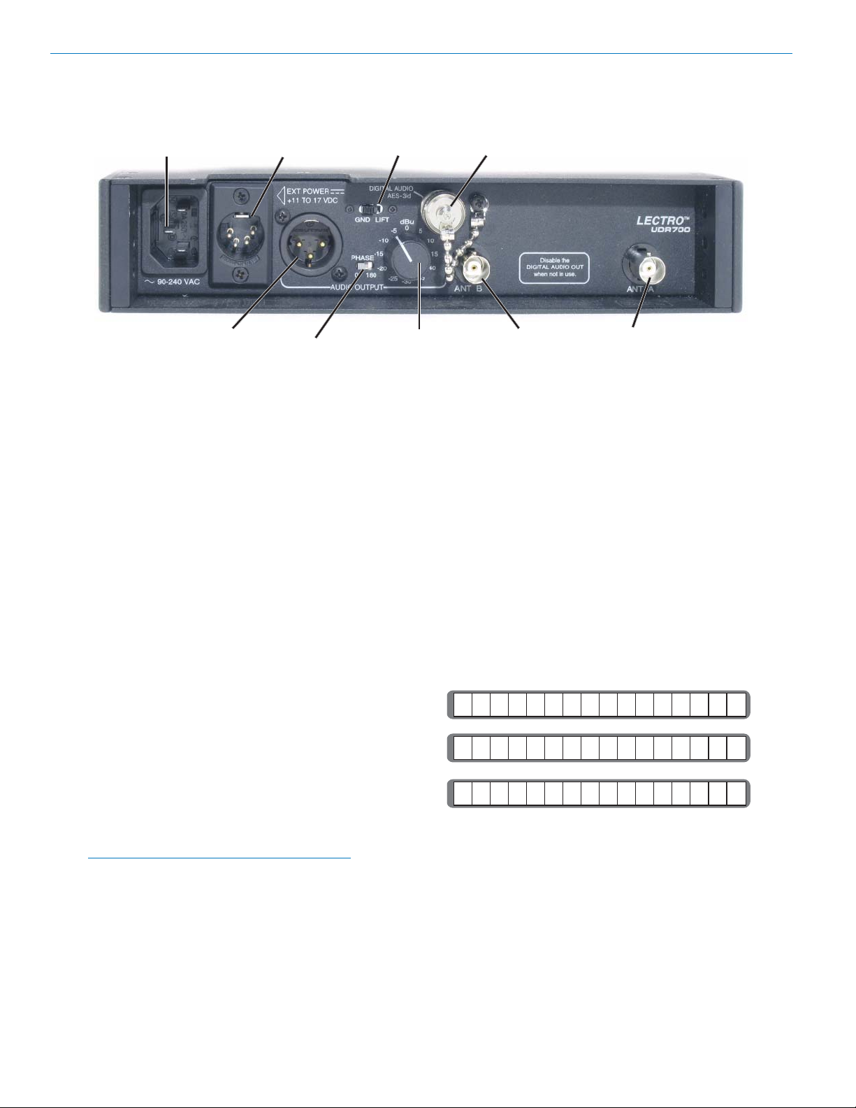
UDR700 Rear Panel
AC Power EXT Power
Input Connector Connector GND LIFT Digital Audio AES-3id
AUDIO OUTPUT Jack Analog Audio ANT B ANT A
PHASE Switch Output Control
AC Power Supply
The UDR700 has a universal switching power supply
which operates on AC voltages ranging from 95 to 240
Volts, 50 or 60 Hz. Since the power supply is self
protected against line transients, short circuits, and over
current conditions, there is no external fuse.
EXT Power Connector
This 4-pin XLR jack is also provided for connecting to
an external power source (+11 to +17 VDC) if desired.
The EXT POWER Connector accepts a standard 4-pin
female XLR connector wire so that Pin 4 is positive and
Pin 1 is ground.
Analog Audio Output Control
A calibrated control on the rear panel adjusts the output
level in 5 dB increments, calibrated in dBu. This control
adjusts the absolute output level at the rear panel XLR
connector when the transmitter is fully modulated
(maximum audio level). The Analog Audio Output
Control is located after the output transformer allowing
the signal to noise ratio to remain constant regardless
of the control’s setting.
Antenna Jacks
These are standard 50 Ohm BNC terminals for the RF
input to the receiver. Both antennas are required for
diversity mode (normal) operation.
UDR700 Iinformation and Status Display
Menus and Functions
Power Up Sequence
When the UDR700 is powered up, the Information and
Status Display will display three messages in sequence
followed by one of the three tuning menus (Main Tuning
Menu, TV Tuning Menu or Group Tuning Menu).
Buttons Enabled/Disabled
Security Level
Firmware Version/Decoder Firmware Version
BUTTONS ENABLED
SECURITY LEVEL 1
GND/LIFT Switch
The GND/LIFT switch either applies or removes chassis
ground from Pin 1 of the AUDIO OUTPUT jack. Lifting
the chassis ground is useful when AC hum is generated
by a ground loop.
Note: Ground loops can occur when the analog
audio output is connected to remote equipment
powered from a different AC main supply.
Phase 0/180
The PHASE 0/180 switch reverses the polarity of the
analog audio output signal.
Digital Audio Output - AES-3id
A BNC connector providing a digital audio output signal
conforming to the AES-3id standard.
UDR700 V3.0/3.0
The tuning menu displayed is the last tuning menu
displayed prior to the last time the UDR700 was turned off.
Enabling and Disabling the Buttons
The front panel control buttons (MENU, SELECT Up/
Down) can be disabled (locked) to prevent accidental
operational changes during use.
When the UDR700 is turned on, the first message
displayed on the Information and Status Display will be
either BUTTONS ENABLED or BUTTONS DISABLED.
If buttons are disabled, pressing any button causes the
message BUTTONS DISABLED to be displayed briefly
and no action will be taken.
LECTROSONICS, INC. 12
Page 13

Encrypted Digital Wireless System
To toggle between BUTTONS ENABLED and BUTTONS DISABLED, press and hold the SELECT Up
button while setting the POWER switch to On.
Menu Interface
The menu interface consists of six linked menus:
Main Tuning
TV Tuning
Group Tuning
AES Output
Security
Key Generation
The MENU Button is used to cycle through the menus.
The menus are:
Main Tuning Menu
The Main Tuning menu is normally the first screen that
appears on the Information and Status Display after the
power up sequence is complete. This screen shows the
frequency (in MHz) that the UDR700 is tuned to, the
transmitter battery voltage (if actively receiving this
information from the transmitter) and the Frequency
Select Switch settings for the transmitter.
Group Tuning Menu
The Group Tuning menu displays the current group (the
three groups are designated A, B, and C) and the
selected frequency within that group. The Transmitter
Frequency Select Switch settings are shown at right, as
on the other tuning menus.
R
G
PA C H AN
In the Group Tuning menu, the SELECT Up and Down
buttons navigate among the seven frequencies in the
current group. To choose a different group, press either
SELECT Up or Down while holding down the MENU
button.
Note: If one of the tuning menus is active when
the receiver is powered down, the receiver will
return to that same menu following the three boot
messages the next time it is turned on.
1
20
AES Output Menu
The AES Output menu allows toggling the DIGITAL
AUDIO OUTPUT (AES-3id jack at the receiver’s back
panel) on or off. Use the SELECT Up and Down
buttons to change the setting.
6
68 . 1 0
If the transmitter battery is low, the voltage display will
blink. If the transmitter battery is very low, a “Battery
Low” warning message will flash periodically, regardless
of what menu is currently being displayed.
The UDR700 comes preloaded with three groups of
seven selected intermod-free frequencies. In the Main
Tuning menu, the SELECT Up and Down buttons can
be used to navigate among the seven frequencies in
the current group. (See Group Tuning Menu.)
You can also tune the receiver across the 25.5 MHz
block in 100 kHz increments by pressing the SELECT
Up or Down button while pressing and holding the
MENU button. Holding either SELECT button down
activates an autorepeat function for faster tuning.
If pressing any button results in “BUTTONS DISABLED”
being displayed, the front panel buttons have been
disabled. (See ENABLING AND DISABLING THE
BUTTONS.)
8. 7 V 1 9
0
TV Tuning Menu
The TV Tuning menu is just like the Main Tuning menu,
except that the applicable UHF TV channel number is
shown in the center of the display in place of the
transmitter battery voltage. This makes it easier to
avoid occupied UHF TV channels in the geographical
area of operation.
Caution: To minimize the chance that the digital
audio output signal will radiate unwanted RF
energy, this function should be turned off
unless the digital audio output is in use.
Security Menu
The Security menu displays the current security level.
(See The 700 Series Encryption System.)
1
L
This menu also allows decryption in the receiver to be
temporarily turned off. Use the SELECT Up and Down
buttons to toggle between decryption on and off. If the
UDR700 is turned off with decryption disabled,
decryption will automatically be enabled when the unit
is powered up again.
S C R I
Note: The only reason to turn decryption off is to
hear what the received audio sounds like without
the right decryption key. 700 Series transmitters
are incapable of transmitting an unencrypted
signal.
U
E
T
O
Y
N
Key Generation Menu
The Key Generation menu is the entry to the security
key generation process.
A
M
K
E
W
NE
YE
K
?
9147TV001.866
Rio Rancho, NM 13
Press SELECT Up to begin the new key generation
process. (See SETTING THE ENCRYPTION KEY.)
Page 14
UDR700 / UM700 / UT700
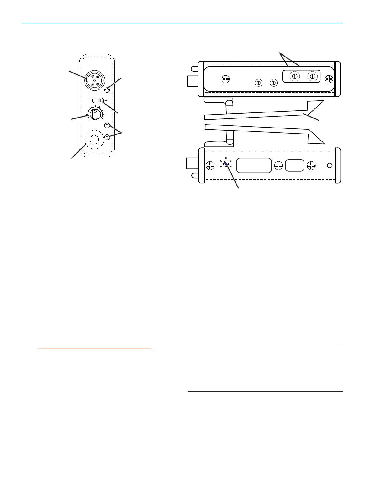
UM700 Controls and Functions
LECTROSONICS
Input Jack
Audio Level Control
SMA Antenna Jack
UM700
ON
OFF
AUDIO
LEVEL
–10
–20
ANTENNA
Font Panel
Power LED
Power ON/OFF Switch
Modulation LEDs
Input Jack
The input jack on the UM700 is a Switchcraft TA5M
connector that accommodates virtually every lavaliere,
hand-held or shotgun microphone available, regardless
of whether they use positive or negative bias. Use a
Switchcraft TA5F connector on the microphone cable or
input adapter cord. The input circuits will also cleanly
handle line level signals up to 300 mV before limiting
(higher with special wiring). (See 5-Pin Input Jack
Wiring, Line Level Signals (UM700).)
Frequency Select Switches
FREQUENCY
1.6MHz
100kHz
0
1
F
2
E
3
D
C
4
5
B
6
A
9
7
8
0
F
1
E
2
3
D
C
4
5
B
6
A
9
7
8
Left Panel
Belt Clip
75 Hz
FCCID:DBZUM700
Lectrosonics, Inc.
150
Made in U.S.A.
35
LF ROLL OFF
Low Frequency Roll-Off Control
SN:
XXXX
Right Panel
Frequency Select Switches
These two 16-position rotary switches (located under a
sliding door on the transmitter’s left side) adjust the
center frequency of the carrier. The 1.6 MHz switch is
the coarse adjustment and the 100 kHz switch is the
fine adjustment.
Power On/Off Switch
The Power On/Off Switch turns the battery power on
and off. Digital muting prevents “thumps” or transients
from occurring in the event that the switch is turned off
or on abruptly.
Power LED
The Power LED glows green when the battery is good
and the ON/OFF switch is set to ON. The LED glows
yellow/orange as the battery voltage drops and finally
glows red when there are about 30 minutes of operation
left (with an alkaline battery). The lamp will blink red
when there are only a few minutes of battery life left.
Caution: A NiMH battery will give little or no
warning when it is depleted. If you wish to use
NiMH batteries in the UM700, we recommend
trying fully charged batteries in the unit, noting
the length of time that the batteries will run the
unit and in the future use somewhat less than
that time to determine when the battery needs
to be replaced.
A weak battery will sometimes cause the Power LED to
glow green immediately after the unit is powered up, but
will soon discharge to the point where the LED will go
red, flicker red or shut off completely (much like a
flashlight with “dead” batteries). If the lamp fails to light,
the battery should be replaced.
Audio Level Control
The front panel Audio Level Control is used to adjust
the incoming audio input level for proper modulation.
Modulation LEDs
The Modulation LEDs provide a visual indication of the
input audio signal level from the microphone and
feedback as the transmitter is turned about the selected
security level.
These two bicolor LEDs can glow either red or green to
indicate modulation levels.
Signal Level -20 LED -10 LED
Less than -20 dB Off Off
-20 dB to -10 dB Green Off
-10 dB to +0 dB Green Green
+0 dB to +10 dB Red Green
Greater than +10 db Red Red
When the transmitter is first switched on, the modulation LEDs blink a code that indicates the current
security level:
Level 1 Security one blink
Level 2 Security two blinks
Level 3 Security three blinks
Antenna
LECTROSONICS, INC. 14
Page 15

Encrypted Digital Wireless System
The insulated flexible galvanized steel cable antenna
supplied with the transmitter is cut to 1/4 wavelength of
the center of the frequency block (the frequency range)
of the transmitter. It is removable via an SMA connector. The SMA connector is a 50 Ohm RF port which can
also be connected directly to test equipment. Replacement antennas are available in pre-cut lengths for
specific frequency blocks, or as a kit with instructions to
cut the antenna for any frequency block. Replacement
antenna is part AMM(xx) where “xx” indicates the
frequency block, i.e.. AMM27 for block 27. (See Accessories Master Catalog, or visit www.lectrosonics.com.)
Adjustable Low Frequency Roll-Off Control
An 18 dB per octave Low Frequency Roll-off Control is
provided in the audio section, with the -3 dB point
adjustable from 35 Hz to 150 Hz. The actual roll-off
frequency will vary according to the low frequency
response of the mic capsule being used.
75 Hz
FCCID:DBZUM700
Lectrosonics, Inc.
Made in U SA.
35
LF ROLL OFF
. .
150
Low Frequency Roll-off Adjustment
The low frequency roll-off control is used to reduce the
undesirable effects of very low frequency audio, such as
those produced by air conditioning systems, automobile
traffic and other sources. Excessive low frequency
content in the audio input can cause overload of the
program audio in recording applications. In sound
reinforcement systems, excessive low frequency
content can cause excessive power amplifier drain or
even damage to loudspeaker systems. A common
example is wind blowing across a microphone, causing
very high levels of low frequency audio (wind noise). By
rotating the roll-off control clockwise, the hinge point of
the roll-off is increased to reduce the level of low
frequencies. In low noise situations, such as a motion
picture production set indoors where environmental
noise is minimal, the control can be rotated counterclockwise to permit low frequency audio to be captured.
XXXX
SN:
UM700 Battery Installation
The transmitter is powered by a standard alkaline or
lithium 9 volt battery. Use alkaline or lithium batteries
for longest life. Standard zinc-carbon batteries marked
“heavy-duty” or “long-lasting” are not adequate. Nicad or NiMH rechargeable batteries provide 1.5 hours
of operation, or less, and will run down quite abruptly.
Unless it is cold, alkaline batteries provide over 4.0
hours of operation. Lithium batteries can be used to
provide up to 7.5 hours. Care should be taken not to
leave a fully discharged lithium battery in the transmitter, as swelling of the battery can make it difficult to
remove from the compartment. The battery status
circuitry is designed for the voltage drop over the life of
alkaline batteries.
To open the battery compartment, press outward on
the cover door in the direction of the arrow as shown in
the drawing. Only firm, sliding pressure is needed to
open and close the battery door. Swing the door open
and take note of the polarity marked inside showing the
location of the positive (+) and negative (-) terminals.
You can see the large and small contact holes inside
the battery compartment with the door open.
Insert the battery correctly and close the cover by
pressing the door closed and across, reversing the
opening procedure illustrated above. If the battery is
inserted incorrectly, the door will not close. Do not
force the door closed.
Press outward on the
battery door in this
direction
Swing the
door open
The Belt Clip
The belt clip may be removed for special applications by
removing the Belt Clip Attachement Screw.
WARNING: USE ONLY THE SCREW THAT IS
SUPPLIED.
The circuitry is tightly packed into this unit. A longer
screw will permanently damage the transmitter! Use
only Lectrosonics PN:28528 which is a Phillips head, 440 x 3/16", FL100 screw.
Belt Clip Attachment Screw location
75 Hz
FCCID:DBZUM700
Lectrosonics Inc.
Made in U S.A.
35
150
LF ROLL OFF
Rio Rancho, NM 15
SN:
,
XXXX
.
Page 16

UDR700 / UM700 / UT700
0
1
2
3
4
5
6
7
8
9
A
B
C
D
E
F
0
1
2
3
4
5
6
7
8
9
A
B
C
D
E
F
UT700 Controls and Functions
Encryption Key Link Power LED
Power On/Off Switch
The Power On/Off slide switch is located on the outside
bottom of the unit and controls power to the transmitter.
Power LED
The Power LED glows green when the battery is good
and the On/Off switch is set to On. The LED glows red
as the battery voltage drops and blilnks when there is
about 30 minutes of operation left with the recommended alkaline battery.
Note: A weak battery will sometimes cause the
POWER LED to glow green immediately after
being put in the unit, but will soon discharge to the
point where the LED will either glow red or the
transmitter shuts down. If the lamp fails to light,
the battery should be replaced.
Caution: A NiMH battery will give little or no
warning when it is depleted. If you wish to use
NiMH batteries in the unit, we recommend
trying fully charged batteries, noting the length
of time that the batteries will run the unit and
in the future use somewhat less than that time
to determine when the battery needs to be
replaced.
When the unit is first turned on, the Power LED also
blinks a code to indicate the current Security Level.
Level 1 - One blink
Level 2 - Two blinks
Level 3 - Three blinks
Battery
Compartment
Power On/Off
Switch
Audio Level
Control
Modulation LEDs
-10 -20
Fine Coarse
Frequency Switches
Hiding the Power LED
This unit has no provision for disabling the LEDs. The
Audio Level LEDs are covered during normal use but
the Power LED is exposed. If the light is objectionable,
we recommend covering the Power LED with a piece of
opaque tape.
Encryption Key Link
The Encryption Key Link is used to connect the transmitter to the UDR700 Series receiver to set an encryption key.
Frequency Select Switches
Two 16-position rotary Frequency Select Switches
(located in the battery compartment) are used to adjust
transmitter’s operating frequency. The Coarse switch
adjustment adjusts the frequency in 1.6 MHz increments and the Fine switch adjusts in 100 kHz increments.
Frequency Switches
Coarse Fine
LECTROSONICS, INC. 16
Page 17

Encrypted Digital Wireless System
Modulation LEDs
The Modulation LEDs (located under the Battery
Compartment Door) provide a visual indication of the
input audio signal level from the microphone. These
two bicolor LEDs can glow either red or green to
indicate modulation levels.
Signal Level -20 LED -10 LED
Less than -20 dB Off Off
-20 dB to -10 dB Green Off
-10 dB to +0 dB Green Green
+0 dB to +10 dB Red Green
Greater than +10 db Red Red
Audio Level Control
The Audio Level control is used to set the audio input
level (or gain) for the proper modulation. Located under
the battery door, this control is rotated while speaking
or singing into the microphone to set the modulation
level.
Audio Level LEDs
Audio Level control
UT700 Battery Installation
between
Battery Compartment
the
Battery
Compartment Cover
Caution: The transmitter is designed for a
standard alkaline or lithium 9 volt battery. It is
important that you use an alkaline or lithium
battery for longest life. Standard zinc-carbon
batteries marked “heavy-duty” or “long-lasting”
are not adequate. Ni-cad rechargeable
batteries will only provide 1.5 hours of
operation, or less, and will run down quite
abruptly.
Alkaline batteries provide over 3.5 hours of operation
under normal conditions. Lithium batteries can provide
up to 6.5 hours. Care should be taken not to leave a
fully discharged lithium battery in the transmitter, as
swelling of the battery can make it difficult to remove
from the compartment. The battery status circuitry is
designed for the voltage drop over the life of alkaline
batteries.
The battery
compartment is
located in the
lower section of the
transmitter,
two printed circuit boards.
Note the two differently
sized holes in the battery
contact pad inside the
Battery Compartment.
Insert the battery so that the large hole in the battery
contact pad will line up with the large contact on the
battery. A spring-loaded plunger in the bottom of the
compartment (opposite the contact pad) secures the
battery in place.
Locked Mode
The UT700 can be placed in a locked mode where
neither the Power On/Off Switch nor the Frequency
Select Switches have any further effect on operation.
This protects the unit from accidental power off or
misadjustment after it has been prepared for use.
To enter locked mode, start with the transmitter turned
on and toggle the Power On/Off Switch off and on
rapidly three times. (Each toggle must be shorter than
two seconds and there must never be more than 10
seconds between toggles.)
After the third toggle, the power LED will go out briefly,
then blink the current security level in red indicating
locked mode.
Locked mode can be cleared by removing the battery.
Note: Removing the transmitter battery may cause
noise in the associated receiver. It is suggested to
turn the receiver audio volume off prior to
removing the transmitter battery.
Rio Rancho, NM 17
The battery status is indicated by the Power LED
located on the UT700 bottom panel. The LED glows
green under normal circumstances when there is
sufficient power left in the battery. The LED changes to
red as the battery voltage drops and starts blilnking
when only about 30 minutes of operation left with the
recommended alkaline battery. Battery status is also
displayed on the Information and Status Display on the
front panel of the UDR700 receiver.
Note: It is possible to insert the battery backwards
and still be able to close the battery door. No
physical damage will occur but the transmitter will
not operate in this condition.
Page 18

UDR700 / UM700 / UT700
LECTROSONICS, INC. 18
Page 19
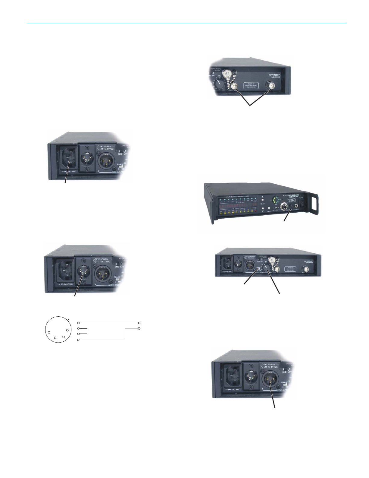
Encrypted Digital Wireless System
System Installation and Operating Instructions
System Setup
1) Locate a suitable operating location where the
receiver will not be subjected to extreme temperature variations and possible bumps and drops. Try
to route all wiring so it will not cross walkways or
aisles.
2) Connect the power. For AC operation, connect the
female end of the power cord to the AC input jack
on the rear panel and plug the other end into a
suitable electrical outlet.
AC Power Input Jack
90 to 240 VAC, 50-60 Hz
Antenna Input BNC Connectors
4) Preset the UDR700 controls as follows:
Audio Monitor Level Control (front panel)
to minimum (CCW)
PHASE Switch (rear panel) to “0”
Analog Audio Output Control (rear panel)
fully CCW (-40 dBu)
If external DC power is desired, a power cord
needs to be fabricated. Use a standard 4-pin
female XLR connector for the receiver end and wire
it according to the diagram below (Pin 4 is positive
and Pin 1 is ground).
External Power Connector 11-17
4
3
4-Pin XLR DC
Powe r Pl ug
3) Connect the antennas. You can use either two
VDC
PIN
1
1
2
2
3
4
Ground
+ 11 to +17 VDC
External DC
Power Supply
remote antennas or two whip antennas with 90degree connectors to operate the UDR700; however, the operating range may be less with the whip
antennas than with the remote antennas. When
using remote antennas, for best performance place
them at least three feet from each other and as high
as possible with a direct line of sight path to the
transmitter.
Audio Monitor Level
(Counterclockwise)
PHASE Switch (0)
Analog Audio Output Control
5) Connect the Audio Output XLR jack to your mixer
input. (Pins 2 and 3 of the XLR jack are HI and LO
and can be reversed with the Phase switch, Pin 1 is
common.)
Audio Output XLR jack
Rio Rancho, NM 19
Page 20

UDR700 / UM700 / UT700
6) Set the front panel POWER switch to On and
observe the POWER UP SEQUENCE. (See
Information and Status Display Menus and Functions.
Warning: Do not turn on the associated
transmitter(s)
.
POWER Switch
7) When the Main Tuning Menu appears observe the
RF Level Indicator LEDs. (If the Main Tuning Menu
is not displayed, press and release the MENU
button to step through the menu selections until it is
displayed.) If any of the RF Level Indicator LEDs
glow or blink, use the SELECT Up or Down button
to locate a clear channel (no RF activity) from one
of the current factory preset frequency group. If a
clear channel is not available using one of the
factory preset frequencies, press and hold the
MENU button, then press the SELECT Up or Down
button to tune across the entire 25.5 MHz frequency block (in 100 kHz steps) to locate one.
(See Information and Status Display Menus and
Functions, Main Tuning Menu and Group Tuning
Menu)
SELECT Up
9) Determine the security level required. (See The
700 Series Encryption System.)
10) Turn the UDR700 Off, then press and hold the
SELECT Down button while turning the UDR700
back on. The display will show the current security
level. The default is Level 1.
11) Use the SELECT Up or Down buttons to choose a
new security level, then press the MENU button to
finalize the security level selection process. The
Information and Status Display displays a message
indicating the level of security (Level 1, 2 or 3).
Note: Changing security levels requires that a new
key be sent to the transmitter before the system
will operate. (See Changing Security Level and
Setting or Resetting Encryption Key.)
Warning: In Security Level 3, both the transmitter
and receiver must be turned on and set to the
same operating frequency prior to setting the
Encryption Key.
12) Press the MENU button to enter the Key Generation Menu. “MAKE NEW KEY?” will be displayed in
the Information and Status Display with an “Up”
arrow to the message’s right. (See Information and
Status Display, Menus and Functions, Key Generation Menu.)
13) Press the SELECT Up button and follow the
directions on the Information and Status Display.
Eventually the prompt “NEW KEY TO TX ^” is
displayed.
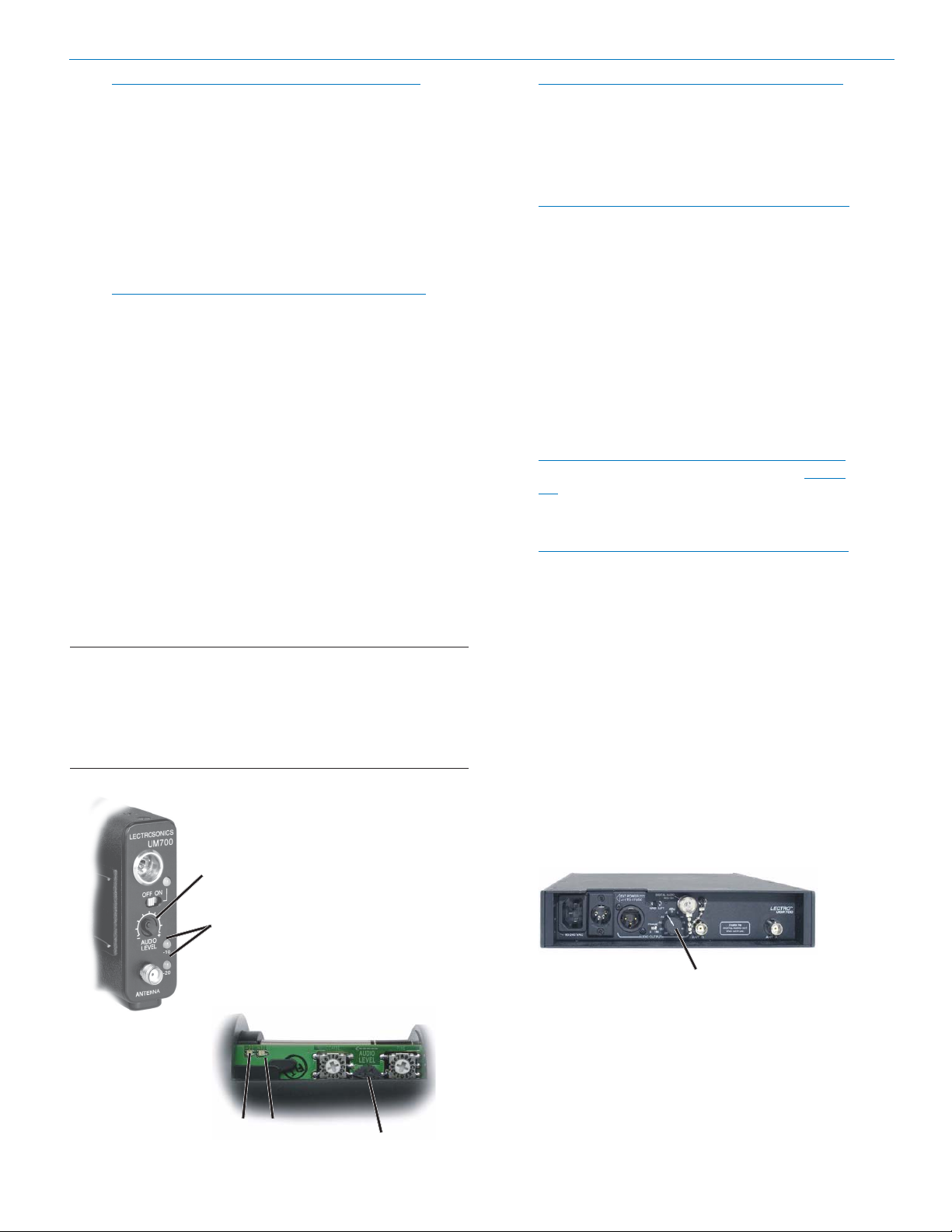
15) Connect the appropriate KEY CABLE Encryption
Cable between the transmitter and the UDR700
and turn on the transmitter.
MENU
SELECT Down
Information and Status Display
8) If necessary, install a fresh battery in the transmit-
ter. (See UM700 Battery Installation and UT700
Battery Installation.) Set the Frequency Select
Switches on the associated transmitter to match
those identified in the receiver’s Main or Group
Tuning Menus (the two rightmost characters on the
Information and Status Display).
Frequency Select Switches
UT700
(Inside Battery Compartment)
Coarse Fine
Coarse Fine
Frequency Select Switches
UM700
UDR700 Security Jack
Encryption
Key Link
UT700 Key Cable
UDR700
Security Jack
UM700 Key Cable
UT700
Power LED
UM700
Modulation LEDs
UM700 Input Jack
LECTROSONICS, INC. 20
Page 21
Encrypted Digital Wireless System
Note: Each transmitter uses a different Encryption
Cable. (See Encryption Key Cables.)
16) Press the SELECT Up button on the UDR700 to
send the encryption key to the transmitter. Depending on the transmitter, the Power LED on the UT700
or the two Modulation LEDs on the UM700 blink to
confirm receipt of the new key.
Level 1: 1 blink
Level 2: 2 blinks
Level 3: 3 blinks
Note: In Security Levels 1 and 2, you may program
as many transmitters as you like to match the
receiver. Repeat steps 15 and 16 for each
transmitter. This will transmit the same encryption
key to each transmitter; however, once you leave
this prompt, this particular encryption key can
never again be sent out of the Security jack to a
transmitter. A new encryption key will have to be
created. In Security Level 3, each encryption key
may be sent to only one transmitter.
17) Depending on the unit, hold the microphone for the
belt pack transmitter or hold the hand held transmitter in the same position that it will be used in actual
operation.
18) While speaking or singing at the same voice level
that will actually be used, observe the Audio Level
LEDs. Adjust the Audio Level control until the -20
LED occasional blinks red and the -10 LED glows
steady green.
Signal Level -20 LED -10 LED
Less than -20 dB Off Off
-20 dB to -10 dB Green Off
-10 dB to +0 dB Green Green
+0 dB to +10 dB Red Green
Greater than +10 db Red Red
UM700 Belt Pack
Note: Different voices will usually require different
settings of the AUDIO LEVEL control, so check
this adjustment as each new person uses the
system. If several different people will be using the
transmitter and there is not time to make the
adjustment for each individual, adjust it for the
loudest voice.
Note: In the UT700, if you find that the Audio Level
control is set to minimum and the -20 LED still
glows green, then adjust the preamp level control
located under the microphone wind screen. (See
VARIMIC™ CONTROLS.) If you adjust the
preamp level control, you will need to repeat steps
19 and 20.
19) If you are using the UT700 hand held microphone,
replace the Battery Compartment Cover.
20) Once the transmitter gain has been adjusted, the
audio levels for the rest of the system can be set.
Set the UDR700 Analog Audio Output Control to
midrange.
Notes: The transmitter Audio Level Control should
not be used to control the volume of your sound
system or recorder levels. This gain adjustment
matches the transmitter gain with the user’s voice
level and microphone positioning.
Note: The UDR700 receiver needs at least 5 uV of
RF signal to begin operating - this is the
approximate squelch threshold. Between 5 uV
and 10 uV, reception will be marginal and brief
gaps in the audio may occur if the receiver
squelches. Check to see that at least the lowest
four RF LEVEL LEDs stay lit when the transmitter
is turned on.
21) Operate the wireless system and fine tune the
receiver analog audio output level as required by
your equipment. The input levels on different
equipment vary. Try different settings of the Analog
Audio Output Control to listen to the results. If the
output of the receiver is too high, you may hear
distortion or a loss of the natural dynamics of the
audio signal. If the output is too low, you may hear
steady noise (hiss) along with the audio.
Audio Level Control
Modulation LEDs
Analog Audio Output Control
UT700 Hand Held
-20 -10
Audio Level LEDs
Rio Rancho, NM 21
Audio Level control
Page 22

UDR700 / UM700 / UT700
Note: The -40 setting is approximately equal to 10
mV, the 0 position will give 0.775 VRMS, and the
+15 setting will allow up to 4.4 VRMS when the
transmitter is fully modulated. The correct setting
will depend on the requirements of your sound or
recording system.
22) If necessary, perform a walk test to map the effective operating range for the transmitter(s) prior to
the beginning of the function.
Note: In Security Level 2, if you wander out of
range for more than 10 seconds, the transmitter
must be turned off, then on again to resynchronize
with the receiver. In Security Level 3, if you
wander out of range for more than 10 seconds, a
new encryption key will have to be generated for
the system to operate.
Changing the Security Level
1) Determine the new security level. (See The 700
Series Encryption System.)
2) Press and hold the SELECT Down button while
powering up the receiver. The display will show the
current security level. (Default is Level 1.)
3) Use the SELECT Up or Down buttons to choose a
new security level, then press the MENU button to
finalize the security level selection process. The
Information and Status Display will then display a
message indicating the level of security (Level 1, 2
or 3). Pressing the MENU button again enters the
key generation process.
encryption key (or press MENU to cancel creating a
new key and return to the MAIN TUNING MENU
display). Follow the directions on the Information
and Status Display until the prompt “NEW KEY TO
TX ^” is displayed.
3) Connect the appropriate Key Cable between the
transmitter and the UDR700, then turn on the
transmitter.
Note: Each transmitter uses a different Key Cable.
(See Encryption Key Cables.)
4) Press the SELECT Up button on the UDR700 to
send the encryption key to the transmitter. Depending on the transmitter, the Power LED on the UT700
or the two Modulation LEDs on the UM700 blink to
confirm receipt of the new key.
Level 1: 1 blink
Level 2: 2 blinks
Level 3: 3 blinks
Note: In Security Levels 1 and 2, you may program
as many transmitters as you like to match the
receiver. Repeat steps 3 and 4 for each
transmitter. This will transmit the same encryption
key to each transmitter; however, once you leave
this prompt, this particular encryption key can
never again be sent out of the Security jack to a
transmitter. A new encryption key will have to be
created. In Security Level 3, each encryption key
may be sent to only one transmitter.
Note: Changing security levels requires that a new
key be sent to the transmitter(s) before the system
will operate.
SELECT Up
MENU
SELECT Down
Information and Status Display
Setting the Encryption Key
Note: In Security Levels 1 and 2, any number of
transmitters can receive the same encryption key.
In Security Level 3, only one transmitter may
receive the encryption key. (See The 700 Series
Encryption System.)
1) To set a new encryption key, press the MENU
button to scroll through the menus until the SECURITY MENU is displayed in the Information and
Status Display. Press MENU once more to enter
the Key Generation Menu. “MAKE NEW KEY?” will
be displayed in the Information and Status Display
with an “Up” arrow to the message’s right.
2) Press the SELECT Up button to create a new
UDR700 Security Jack
Encryption
Key Link
UT700 Key Cable
UDR700
Security Jack
UM700 Key Cable
UT700
Power LED
UM700
Modulation LEDs
UM700 Input Jack
LECTROSONICS, INC. 22
Page 23
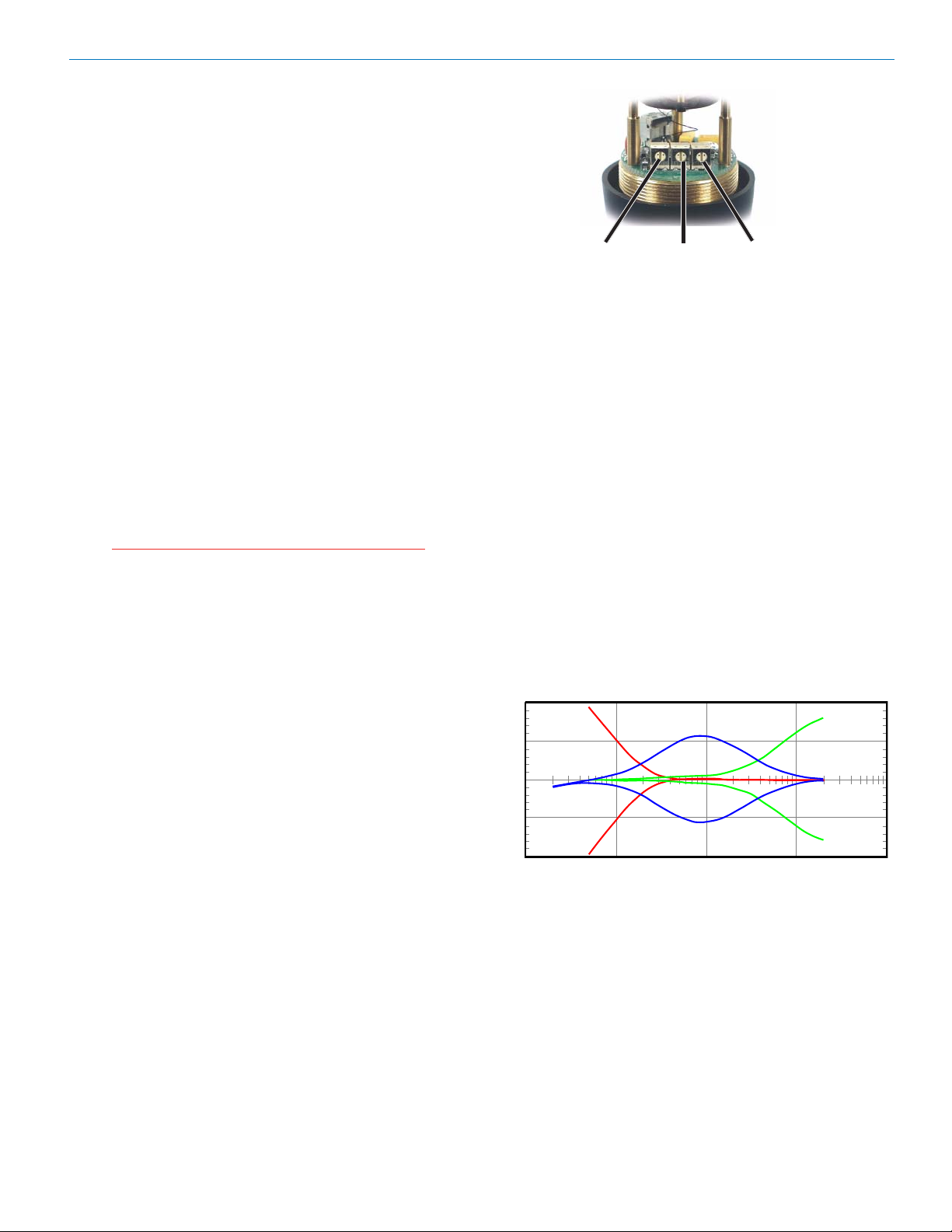
Protecting the Encryption Key
0
The encryption key is never displayed, and once a key
transfer session is complete, the existing key can never
again be transferred out the receiver’s security port.
However, the key is stored inside the transmitter and
the receiver, so you should treat the equipment as you
would a key, storing it in a safe place for as long as the
key is important.
Keep in mind that old keys could be used to decrypt old
transmissions, if someone had the means and desire to
make such recordings. Also, overwriting an old key with
a new one does not necessarily place the old key
beyond the reach of someone with unlimited resources
if they can obtain your equipment. Amazing feats of
data recovery from overwritten EEPROM chips have
been demonstrated.
For maximum security, it is recommended that you set a
new key often, ideally before and after each use of the
system, and that you always store the equipment in a
physically secure location.
Note that in Security Level 3, the equipment itself
enforces the most important part of this policy, namely
that no key shall ever be used more than once.
UT700 Vari-Mic™ Controls
Caution: Due to the high RF levels surrounding
the transmitter, the sound of the Varimic
capsule may be temporarily affected if the
metal windscreen is not in place. Always make
the final decision about sound balance and
quality with the windscreen in place.
The VariMic™ head includes adjustments for the
microphone element’s Bass, Midrange and Treble
response. There is also an attenuation adjustment to
provide up to 15 dB of additional headroom if needed.
These controls can be accessed by removing the
windscreen. To remove the windscreen, grasp the body
of the transmitter in one hand and the windscreen in the
other hand. Unscrew the windscreen counterclockwise
and then carefully slide the windscreen past the mic
element.
Encrypted Digital Wireless System
Bass (LO) Mid (MID) Treble (HI)
• Set flat (as shown in illustration), the mic capsule
has a very wide dynamic range and sounds a lot
like a large competitor’s top line condenser mic.
• Bass cut gives a dry but highly intelligible sound.
Crisp.
• Bass boost “fattens” the sound but is very listenable. Does not get midbass boomy.
• Midrange cut sounds very smooth, very sweet.
Almost like a “crooner” quality.
• Midrange boost is likely to be useful in a system
that is midrange shy.
• Treble cut has a “mellow” sound. The capsule has a
solid high end so a little cut does not ruin the
response.
• Treble boost might be fine on some sound systems.
The sound doesn’t get harsh (showing that the
response was smooth) but sibilants are a little too
much. Should be used in moderation.
UT200 Bass/Midrange/Treble Boost/Cut
+10
+5
dB
-5
Bass / Mid / Treble (LO / MID / HI)
The bass and treble controls will boost/cut by up to
-10
10Hz
100Hz
1KHz
10KHz
approximately 8 dB while the Mid control will boost/cut
up to about 6 dB. These controls operate as standard
tone controls. Counterclockwise will reduce the response in that band and clockwise will provide a true
boost.
Rio Rancho, NM 23
Page 24
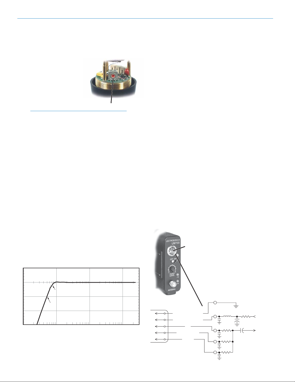
UDR700 / UM700 / UT700
Preamp Level Control
The VariMic™ head includes an attenuator to provide
an additional 15 dB of headroom when needed. The
attenuator should only be used when the normal Audio
Level Control is already turned down as far as it will go
and the signal through the mic
is still too hot. The attenuator
control is a 16-position switch
marked 0 through F. “F” is
minimum attenuation or the
highest signal level. “0” is
maximum attenuation or the
lowest signal level. For the
maximum amount of headroom, set the switch to “0.”
Note: The attenuator should not be used as a level
control. The Audio Level control inside the battery
compartment is the main level control. Adjust the
attenuator only when the Audio Level control is
turned completely down and more headroom is
still needed. Be sure to set the attenuator back to
its original setting (minimum attenuation or “F”) for
normal operation.
Preamp Level Control
Bass Filter
In addition to the tone controls, the UT700 also has a
built in bass filter. This filter is fixed and cannot be
adjusted or defeated. Low frequency noise is more of a
problem with wireless microphones than with conventional microphones. With a regular mic, low frequency
wind noise, breath thumps or handling rumble can be
filtered out at the control board before the noise causes
problems with the following electronic circuits or
speaker systems. But with a wireless microphone, the
electronics that will be overdriven are right in the
wireless microphone. Filtering at the control board is
much too late. To solve this problem, the VariMic has a
low frequency filter that is so sharp that it can remove
low frequency noise without affecting any wanted
vocals. It consists of a 36 dB per octave filter circuit to
sharply remove low frequency noise below 75 Hz
without affecting vocal fundamentals.
20
0dB
-20
-40
-60
10Hz
VariMic Low Frequency Roll-off Filter
-3dB @ 71Hz
-20dB @ 50Hz
100Hz
1KHz
10KHz
5-Pin Input Jack Wiring (UM700)
The wiring diagrams shown in Wiring Hookups For
Different Sources represent the basic wiring configurations necessary for the most common types of microphones and other audio inputs. Some microphones
may require extra jumpers or a slight variation in the
diagrams shown.
It’s virtually impossible to keep completely up to date on
changes that other manufacturers make to their products. It is possible that you may encounter a microphone that differs from those illustrated. If this occurs
please visit our web site (http://www.lectrosonics.com)
or call our toll-free number listed in the back of this
manual for assistance. Our Service Department can
answer your questions regarding microphone compatibility.
When used on a wireless transmitter, the microphone
element is in the proximity of the RF coming from the
transmitter. The nature of electret microphones makes
them sensitive to RF, which can cause problems with
the microphone/transmitter compatibility. If the electret
microphone is not designed properly for use with
wireless transmitters, it may be necessary to install a
chip capacitor in the mic capsule or connector to block
the RF from entering the electret capsule. (See RF
Bypassing.)
PIN 1- Shield (ground) for positive biased electret
lavaliere microphones. For the increasingly rare
negative biased electret lavaliere microphones, it is
the bias voltage source. It is also the shield
(ground) for dynamic microphones and line level
inputs.
PIN 2 - Shield (ground) for negative biased electret
lavaliere microphones. Bias voltage source for
positive biased electret lavaliere microphones.
1
2
3
4
5
Input Circuit
Input
Jack
NEG GND (OR BIAS)
POS BIAS (OR GND)
MIC
SOURCE LOAD
LINE IN
PIN 3 - Low impedance microphone level input for dynamic
microphones. Also accepts
hand-held electret microphones
that have their own battery or
power supply.
PIN 4 - 4 k Ohm source load for
non-Lectrosonics electret
microphones. Use in conjunction with other pins to provide
attenuation of high level input
signals.
+
+
10uF
1k
5V Mic Bias
To Mic Amp
FB
330pF
100
330pF
4k
330pF
40k
330pF
LECTROSONICS, INC. 24
Page 25

Encrypted Digital Wireless System
R
PIN 5 - 40 k high impedance, line level input for
tape decks, mixer outputs, musical instruments, etc.
AUDIO
PIN
1
2
1
4
5
3
2
3
4
TA5F
5
PLUG
PIN
1
2
1
4
5
3
2
3
4
TA5F
5
PLUG
PIN
1
2
1
4
5
3
2
3
4
TA5F
5
PLUG
PIN
1
2
1
4
5
3
2
3
4
TA5F
5
PLUG
PIN
1
2
1
4
5
3
2
3
4
TA5F
5
PLUG
PIN
1
2
1
4
5
3
2
3
4
TA5F
5
PLUG
SHIELD
SLEEVE
TIP
BIAS
AUDIO
SHIELD
AUDIO
SHIELD
BIAS
AUDIO
SHIELD
AUDIO
SHIELD
SHIELD
3 WIRE ELECTRET MIC
POSITIVE BIAS
2 WIRE ELECTRET MIC
POSITIVE BIAS
3 WIRE ELECTRET MIC
NEGATIVE BIAS
2 WIRE ELECTRET MIC
NEGATIVE BIAS
LINE LEVEL
RCA or 1/4 " PLUG
PIN
1
2
1
2
3
3
Dynamic LO Z mic or electret with
DYNAMIC
MIC LEVEL
manufacturer’s power supply.
Wiring Hookups for Different Sources (UM700)
RF Bypassing (UM700)
Some mics require RF protection to keep the transmitter signal from affecting the capsule, even though the
transmitter input circuitry is already RF bypassed (see
5-Pin Input Jack Wiring schematic diagram ).
If the mic is wired as directed, and you are having
difficulty with squealing, high noise, or poor frequency
response, RF is likely to be the cause.
The best RF protection is accomplished by installing
330 pF bypass capacitors at the mic capsule. If this is
not possible, or if you are still having problems, capacitors can be installed on the mic wires inside the TA5F
connector housing.
The 330 pF capacitors are available from Lectrosonics.
2 WIRE MIC 3 WIRE MIC
Preferred locations for bypass capacitors
SHIELD
Please specify the part number for the desired lead style.
Leaded capacitors: P/N 15117
Leadless capacitors: P/N SCC330P
Note: The M150-7005P microphone is bypassed
correctly for use with the UM700 Encrypted Digital
Transmitter and is the recommended lavaliere
microphone for the 700 Series wireless
microphone system.
Line Level Signals (UM700)
The normal hookup for line level signals provides 40 dB
of attenuation allowing signal levels up to 30 V to be
applied without limiting. The normal hookup configuration can be modified for situations that require higher
levels of headroom, or lower levels of attenuation.
AUDIO
PIN
PIN
PIN
1
2
3
4
5
1
2
3
4
5
1
2
3
4
5
4
3
TA5 F
PLUG
4
3
TA5 F
PLUG
4
3
TA5 F
PLUG
1
5
2
1
5
2
1
5
2
Normal Hookup
More Headroom
Lower Line Level
Hookup
SHIELD (GND)
AUDIO
SHIELD (GND)
100k
SHIELD (GND)
AUDI O
Normal hookup connects the Signal Hot (Audio) to pin
5, Signal Gnd (Shield) to pin 1, and both pins 3 and 4
jumped to pin 1.
If even more headroom is required, insert a 100 k
resistor in series with pin 5 (Audio). Put this resistor
inside the TA5F connector to minimize noise pickup.
For situations where lower than normal line levels (less
than 1 V) are expected, use the Lower Line Level Hook
Up: Signal Hot (Audio) to pin 5, Signal Gnd (Shield) to
pin 1, and pin 4 jumpered to pin 1. This configuration
provides 20 dB attenuation allowing signal levels up to 3
V to be applied without limiting.
Encryption Key Cables
Each digitally encrypted transmitter uses a different
encryption key cable. The configuration of these cables
is listed below.
SLEEVE
Mini Plug
UT700KEY CABLE
TIP
SLEEVE
TIP
3.5 mm Plug
CAPSULE
SHIELD
AUDIO
AUDIO
TA5F
CONNECTOR
CAPSULE
BIAS
Alternate locations for bypass capacitors
TA5F
CONNECTO
Mini Plug
UM700KEY CABLE
SLEEVE
TIP
SHIELD
DATA
PIN
1
2
3
4
5
5
3
TA5F
PLUG
14
2
Rio Rancho, NM 25
Page 26

UDR700 / UM700 / UT700
LECTROSONICS, INC. 26
Page 27

Encrypted Digital Wireless System
Troubleshooting
This manual applies only to UDR700 version 3.0/3.0 and higher.
Power Problems
UDR700
Display not lit or dimly lit Power cord between main power supply and UDR700 disconnected or
defective.
External power supply disconnected, defective or inadequate.
The External DC power input is protected by an auto-reset polyfuse. If
external DC power is used, disconnect External DC power source
and wait about 10 seconds for the fuse to reset, then reconnect
power source.
Main power supply defective.
UM700
Power LED does not glow when
transmitter Power ON/OFF Switch
set to ON Battery is dead, or too low to be used.
Battery is inserted backwards.
No Modulation LEDs Battery dead or in backwards. Check Power LED.
Audio Level Control turned all the way down.
Mic capsule is damaged or malfunctioning.
Mic cable damaged or mis-wired.
UT700
Power LED does not glow when
transmitter Power On/Off Switch
set to On Battery is inserted backwards.
Battery is dead, or too low to be used.
No Modulation LEDs Battery dead or in backwards. Check Power LED.
Audio Level Control turned all the way down.
Mic capsule is damaged or malfunctioning. Contact the factory for
repair.
RF Problems
Antenna Phase Combining Indicator on
UDR700 has three LEDs glowing but
never moves The ROTA-VERSITY switch is set to the A or B position (using only
one antenna) instead of the normal, center position (using both
antennas).
An antenna may be disconnected, have a bad connector or defective
antenna cable.
No LEDs glow on Receiver RF Level
Indicator Receiver not turned on.
Transmitter not turned on, or battery is dead.
A receiver antenna may be disconnected, have a bad connector or
defective cable.
Transmitter and receiver not on same frequency.
Transmitter antenna not connected. (UM700 only)
Operating range is too great.
RF LEVEL is weak, but Antenna
Phase Combining Indicator LEDs glow
and move An antenna may have bad connector and damaged cable.
The antennas may need to be moved or reoriented.
Improper length of UHF whip antenna, or wrong antenna.
Transmitter is 100 kHz (one switch position) off from the receiver
frequency.
Rio Rancho, NM 27
Page 28

UDR700 / UM700 / UT700
Audio Problems
No audio output, audio leds blinking
in sequence, LED display occasionally
flashes "POWER TX OFF+ON" or
"NEW KEY REQUIRED". System is operating in security level 2 ("POWER TX OFF+ON") or 3
("NEW KEY REQUIRED") and is not synchronized. Either the
receiver did not pick up the start of the transmission or the
transmitter was out of reception range for more than ten seconds.
To correct this condition in security level 2, simply turn the
transmitter off and on again. In level 3, it will be necessary to
generate a new key. (For detailed instructions on generating a new
key, see SETTING THE ENCRYPTION KEY.)
Receiver indicates RF but no audio, and
problem is not encryption key Ensure that the transmitter and receiver are set to the same
frequency.
Transmitter Audio Level Controls misadjusted.
No sound (or low sound level),
receiver indicates proper
audio modulation Receiver output level set too low.
Receiver output disconnected, audio output cable is defective or
connector is wired incorrectly.
Sound system or recorder input is turned down.
Receiver outputs an extremely loud,
hissy or swishy sound Encryption keys in transmitter and receiver do not match.
Poor signal to noise ratio Transmitter gain set too low.
Noise may not be in wireless system. Mute the audio signal at the
transmitter and see if noise remains. If the noise remains, then turn
the power off at the transmitter and see if it remains. If the noise is
still present, then the problem is not in the transmitter.
If noise is still present when the transmitter is turned off, try lowering
the audio output level on the receiver rear panel and see if the noise
lowers correspondingly. If the noise remains, the problem is not in
the receiver.
Receiver output does not match the input of the device it is feeding.
Try increasing the output level of the receiver and lowering the input
gain on the device the receiver is feeding.
Hiss and noise, audible dropouts Transmitter gain (audio level) far too low.
Receiver antenna missing or obstructed.
Operating range too great.
Receiver and Transmitter Frequency Select Switches not set to the
same channel.
RF interference. Reset both transmitter and receiver to a clear
channel.
Note: Resetting operating frequency will require resending encryption
key in Security Level 3.
Distorted sound, motorboating Transmitter gain (audio level) is too high. Check Modulation LEDs on
transmitter and receiver as transmitter is being used.
Receiver output may be mismatched with the sound system or
recorder input.
Excessive wind noise or breath “pops.” Reposition microphone, or use
a larger windscreen (UT700), or both.
RF feedback getting into VariMic mic capsule. Ensure that the
windscreen is present and screwed down snugly.
Transmitter is not set to same frequency as receiver.
RF interference. Reset both transmitter and receiver to a clear
channel.
LECTROSONICS, INC. 28
Page 29

Encrypted Digital Wireless System
Excessive feedback Transmitter gain (audio level) too high. Check gain adjustment
and/or reduce receiver output level.
Microphone too close to speaker system.
Move microphone closer to the user’s mouth, and lower the
sound system volume.
Microphone has a “whine” noise in
the background which varies as the mic
cable is moved. (UM700 specific) The 700 Series modulation has an AM component which is more
easily detected than FM by sensitive audio circuits. A microphone
that works fine on an FM system might not work on a 700 series
system. To protect the microphone from RF it is necessary to
bypass it effectively at both ends of the cable. Ensure that bypass
capacitors are installed inside the connector housing. If the mic is
not sufficiently bypassed at the capsule, it may be necessary to use
a different type of microphone. The UM700 transmitter is shipped
with an M150 microphone which should work.
Note: The microphone plug wiring is different for the UM700 transmitter
than for other Lectrosonics models. The M150 microphone supplied
with the UM700 transmitter will not work with Lectrosonics 185/187
Series VHF belt-pack transmitters.
Rio Rancho, NM 29
Page 30

UDR700 / UM700 / UT700
Specifications
Overall System
Latency: 2.5 ms
Operating principle: Proprietary digital modulation with encryption
Modulation type: Modified pi/4 DQPSK
Sample rate: 44.1 ksps
Audio coder: Proprietary sub-band ADPCM
Encryption key length: 128 bit (300 trillion trillion trillion keys)
Bit rate: 220,500 bps including packet overhead
Operating frequencies: Block 22 563.200 - 588.700
(depending upon local regulations) Block 23 588.800 - 607.900 and
614.100 - 614.300
Block 24 614.400 - 639.900
Block 25 640.000 - 665.500
Frequency selection: 256 frequencies in 100 kHz steps
Frequency Adjustment Range: 25.5 MHz
System Specifications
Audio frequency response: 40 Hz to 20 kHz, +/- 1dB
(with UM700 transmitter)
Audio dynamic range: >100 dB before limiting
Audio Distortion: 0.05% THD + noise at 1 kHz
UDR700 Digital Receiver
Receiver Type: Double conversion, superheterodyne,
244 MHz and 10.7 MHz
Frequency Stability: +/- 0.002%
Front end selectivity: >22 dB at +/- 4 MHz
Sensitivity: 5 uV for 100 dB S/N ratio
Squelch quieting: > 125 dB
Image/Spurious rejection: > 100 dB
Third order intercept: +12 dBm
Diversity technique: Rota-versity antenna combining
Antenna inputs: Dual BNC 50 Ohm
Modulation Type: Modified pi/4 DQPSK
Sample Rate: 44.1 ksps
Bit Rate: 220,500 bps
Audio Coder: Proprietary sub-band ADPCM
Encryption Key Length: 128-bit (over 300 trillion, trillion, trillion keys)
Audio outputs: Analog: -40 dBu to +15 dBu
Digital: AES-3id
Monitor out: Front panel 1/4" jack; 0 to 110 mV RMS.
Power Options: 90 to 240 VAC, 50/60 Hz, 10 Watts
11 to 17 VDC, 10 Watts
Weight: 3 lbs., 9 ozs.
Dimensions: 8.2" wide x 1.73" high x 10.6" deep
UM700 Digital Transmitter
RF Power output: 50 mW (nominal)
Frequency stability: ± 0.001%
Equivalent input noise: –119 dBV, A-Weighted
Spurious radiation: 70 dB below carrier
Input Level: Nominal 2 mV to 300 mV before limiting
Greater than 1V maximum with limiting
Input impedance: Taps provided for 100, 4k, 40k Ohm
Input compressor: Dual-envelope limiter; 30 dB range
Gain control range: 43 dB; semi-log rotary control
Modulation indicators: Dual multi-color LEDs indicate modulation
level in 4 steps at -20, -10, 0, +10 dB with
green and red indications
Low frequency roll-off adjustment: –18 dB/octave; 35 Hz to 150 Hz
Controls: 2 position “ON-OFF” slide switch.
Audio Input Jack: Switchcraft 5-pin locking (TA5M)
Note: The M150-7005P microphone is bypassed correctly for use
with the UM700 Encrypted Digital Transmitter and is the
recommended lavaliere microphone for the 700 Series wireless
microphone system.
Antenna: Detachable, flexible 1/4 wave insulated
Battery: Precision compartment auto-adjusts to accept
Battery Life: 4 hours (alkaline); 7.5 hours (lithium)
Weight: 6.3 ozs. including battery
Dimensions: 3.1 x 2.4 x .75 inches
Emission Designator: 180KQ2E
The FCC requires that the following statement be included in this manual:
This device and its antenna(s) must operate with a separation distance of at least
2.5 cm from all persons and must not be co-located or operating in conjunction
with any other antenna or transmitter.
Front panel knob adjusts audio gain.
Recessed control on side panel adjusts low
frequency rolloff. Rotary switches on side
panel adjust transmitter frequency.
bronze cable. 50 Ohm port allows connection
to test equipment.
any known alkaline 9 Volt battery.
UT700 Digital Transmitter
RF Power output: 50 mW (nominal)
Frequency stability: ± 0.001%
Spurious radiation: 70 dB below carrier
Input compressor: Dual-envelope limiter; 30 dB range
Gain control range: 43 dB; semi-log rotary control
Modulation indicators: Dual multi-color LEDs indicate modulation
Controls: 2 position “ON-OFF” slide switch. Knob in
Battery: Precision compartment auto-adjusts to accept
Battery Life: 3.5 hours (alkaline); 6.5 hours (lithium)
Weight: 12.4 ozs. with VariMic™ cardioid capsule and
Dimensions: 9” long, x 2.05” diameter at largest point with
Emission Designator: 180KQ2E
The FCC requires that the following statement be included in this manual:
This device and its antenna(s) must not be co-located or operating in conjunction
with any other antenna or transmitter.
Specifications subject to change without notice.
level in 4 steps at -20, -10, 0, +10 dB with
green and red indications
battery compartment adjusts audio gain.
Rotary switches in battery compartment
adjust transmitter frequency.
any known alkaline 9 Volt battery.
lithium battery
VariMic™ cardioid capsule
LECTROSONICS, INC. 30
Page 31

Encrypted Digital Wireless System
Rio Rancho, NM 31
Page 32

UDR700 / UM700 / UT700
Replacement Parts and Accessories
Part No. Description
A500RA Right angle, flexible whip UHF
antenna
A600 Log Periodic Dipole Array antenna
A700A Log Periodic Dipole Array antenna
AMMxx Precut UHF antennas cut to specific
blocks with SMA jacks.
AMM Kit UHF antenna for UHF belt-pack
transmitters with SMA jacks. Cut to
frequency with supplied template.
21499 Replacement AC power cord (US
NEMA Type Plug)
M150-7005P Replacement lavaliere microphone
for UM700 transmitter
RMP200-1 Rack mount kit for single UDR700
receiver
RMP200-2 Rack mount kit for two UDR700
receivers
UM700 Key Cable Encryption Key setup cable for
UM700 Transmitter
UT700 Key Cable Encryption Key setup cable for
UT700 Tranmitter
ARG2 - ARG100 Coaxial cables for remote antennas
with BNC connectors on both ends
MC40 Audio cable adapter-Female XLR to
TA5F 5-pin
A4F 4-pint XLR plug for making External
DC Power Cable for UDR700
BCWIRE Replacement belt clip for UM700
35804 Transmitter pouch for all hand-held
transmitters
LECTROSONICS, INC. 32
Page 33

Encrypted Digital Wireless System
Service and Repair
If your system malfunctions, you should attempt to correct or isolate the trouble before concluding that the equipment
needs repair. Make sure you have followed the setup procedure and operating instructions. Check the interconnecting cables and then go through the Troubleshooting section in this manual.
We strongly recommend that you do not try to repair the equipment yourself and do not have the local repair shop
attempt anything other than the simplest repair. If the repair is more complicated than a broken wire or loose connection, send the unit to the factory for repair and service. Don’t attempt to adjust any controls inside the units. Once set
at the factory, the various controls and trimmers do not drift with age or vibration and never require readjustment.
There are no adjustments inside that will make a malfunctioning unit start working.
LECTROSONICS’ Service Department is equipped and staffed to quickly repair your equipment. In warranty repairs
are made at no charge in accordance with the terms of the warranty. Out-of-warranty repairs are charged at a modest
flat rate plus parts and shipping. Since it takes almost as much time and effort to determine what is wrong as it does
to make the repair, there is a charge for an exact quotation. We will be happy to quote approximate charges by phone
for out-of-warranty repairs.
Returning Units for Repair
For timely service, please follow the steps below:
A. DO NOT return equipment to the factory for repair without first contacting us by letter or by phone. We need to
know the nature of the problem, the model number and the serial number of the equipment. We also need a
phone number where you can be reached 8 A.M. to 4 P.M. (U.S. Mountain Standard Time).
B. After receiving your request, we will issue you a return authorization number (R.A.). This number will help speed
your repair through our receiving and repair departments. The return authorization number must be clearly shown
on the outside of the shipping container.
C. Pack the equipment carefully and ship to us, shipping costs prepaid. If necessary, we can provide you with the
proper packing materials. UPS is usually the best way to ship the units. Heavy units should be “double-boxed” for
safe transport.
D. We also strongly recommend that you insure the equipment, since we cannot be responsible for loss of or dam-
age to equipment that you ship. Of course, we insure the equipment when we ship it back to you.
Mailing address: Shipping address: Telephone:
Lectrosonics, Inc. Lectrosonics, Inc. (505) 892-4501
PO Box 15900 581 Laser Rd. (800) 821-1121 Toll-free
Rio Rancho, NM 87174 Rio Rancho, NM 87124 (505) 892-6243 Fax
USA USA
Web: E-mail:
www.lectrosonics.com sales@lectrosonics.com
Rio Rancho, NM 33
Page 34

UDR700 / UM700 / UT700
Microphone Cord Termination
TA5F Connector Assembly
1
2 3
VIEW FROM SOLDER
SIDE OF PINS
4
5
This is the correct way.
0.15"
0.3"
Heatshrink
Tubing
Mic Cord Stripping Instructions
Be sure the shield wire touches the metal crimp
tab. This helps prevent any AM component of the
transmitter signal from entering the mic and
causing a "whine."
Note that this is opposite from our VHF
transmitter wiring where the shield should not
touch any metal part of the housing.
Don't do it this way!
Shield Wire
Crimp
Tabs
Rubber
Insulation
Rubber
Insulation
Crimp
Tabs
LECTROSONICS, INC. 34
Page 35

Encrypted Digital Wireless System
Rio Rancho, NM 35
Page 36

LIMITED ONE YEAR WARRANTY
The equipment is warranted for one year from date of purchase against defects in
materials or workmanship provided it was purchased from an authorized dealer. This
warranty does not cover equipment which has been abused or damaged by careless
handling or shipping. This warranty does not apply to used or demonstrator equipment.
Should any defect develop, Lectrosonics, Inc. will, at our option, repair or replace any
defective parts without charge for either parts or labor. If Lectrosonics, Inc. cannot
correct the defect in your equipment, it will be replaced at no charge with a similar new
item. Lectrosonics, Inc. will pay for the cost of returning your equipment to you.
This warranty applies only to items returned to Lectrosonics, Inc. or an authorized
dealer, shipping costs prepaid, within one year from the date of purchase.
This Limited Warranty is governed by the laws of the State of New Mexico. It states the
entire liablility of Lectrosonics Inc. and the entire remedy of the purchaser for any
breach of warranty as outlined above. NEITHER LECTROSONICS, INC. NOR
ANYONE INVOLVED IN THE PRODUCTION OR DELIVERY OF THE EQUIPMENT
SHALL BE LIABLE FOR ANY INDIRECT, SPECIAL, PUNITIVE, CONSEQUENTIAL,
OR INCIDENTAL DAMAGES ARISING OUT OF THE USE OR INABILITY TO USE
THIS EQUIPMENT EVEN IF LECTROSONICS, INC. HAS BEEN ADVISED OF THE
POSSIBILITY OF SUCH DAMAGES. IN NO EVENT SHALL THE LIABILITY OF
LECTROSONICS, INC. EXCEED THE PURCHASE PRICE OF ANY DEFECTIVE
EQUIPMENT.
This warranty gives you specific legal rights. You may have additional legal rights which
vary from state to state.
581 Laser Road NE • Rio Rancho, NM 87124 USA • www.lectrosonics.com
(505) 892-4501 • (800) 821-1121 • fax (505) 892-6243 • sales@lectrosonics.com
March 28, 2006
 Loading...