

Page 1

UR195
COMPACT UHF RECEIVER
OPERATING INSTRUCTIONS
and troubleshooting guide
LECTROSONICS, INC.
Rio Rancho, NM
Rio Rancho, NM – USA
1
Page 2

Table of Contents
INTRODUCTION TO THE 195 SYSTEM .............................................................. 3
UT195 TRANSMITTER .......................................................................................................... 3
UM195 TRANSMITTER ......................................................................................................... 3
DUAL-BAND COMPANDOR ................................................................................................. 3
75kHz DEVIATION.................................................................................................................3
NO PRE-EMPHASIS/DE-EMPHASIS ................................................................................... 3
EXCEPTIONAL THERMAL STABILITY ................................................................................ 3
GENERAL TECHNICAL DESCRIPTION - UR195 RECEIVER........................... 4
SIX-POLE HELICAL RESONATOR FRONT-END ............................................................... 4
GaAs FET FRONT-END FILTER COUPLING ..................................................................... 4
DOUBLE BALANCED DIODE MIXERS ................................................................................ 4
10 POLE LINEAR PHASE FILTER ....................................................................................... 4
DIGITAL PULSE COUNTING DETECTOR .......................................................................... 4
2:1 EXPANDER (Dual–Band Compandor) ........................................................................... 5
PILOT TONE MUTE (SQUELCH) ......................................................................................... 5
FRONT PANEL CONTROLS AND FUNCTIONS ................................................. 5
PWR LED ............................................................................................................................... 5
PILOT LED ............................................................................................................................. 5
TRANSMITTER AUDIO LEVEL METER .............................................................................. 5
RF LEVEL INDICATORS ....................................................................................................... 5
OUTPUT LEVEL ADJUST AND RANGE SWITCH .............................................................. 5
POWER SUPPLY .................................................................................................................. 5
MONITOR ............................................................................................................................... 5
POWER SWITCH .................................................................................................................. 5
AUDIO OUTPUT ..................................................................................................... 5
REAR PANEL CONTROLS AND FUNCTIONS ................................................... 6
EXTERNAL POWER JACK ................................................................................................... 6
AUDIO OUTPUT XLR JACK ................................................................................................. 6
RANGE SWITCH ................................................................................................................... 6
ANTENNA CONNECTOR ..................................................................................................... 6
ANTENNA USE AND PLACEMENT ..................................................................... 7
OPERATING INSTRUCTIONS .............................................................................. 8
UR195 REPLACEMENT PARTS and ACCESSORIES ....................................... 8
TROUBLESHOOTING ............................................................................................ 9
POWER SUPPLY AND FUSE ............................................................................................... 9
PILOT TONE SQUELCH ....................................................................................................... 9
ANTENNAS AND RF SIGNAL STRENGTH ......................................................................... 9
AUDIO SIGNAL QUALITY ..................................................................................................... 9
SERVICE AND REPAIR ....................................................................................... 10
RETURNING UNITS FOR REPAIR ..................................................................... 10
SPECIFICATIONS AND FEATURES .................................................................. 11
LIMITED ONE YEAR WARRANTY ..................................................... Back cover
2
Page 3

INTRODUCTION TO THE 195 SYSTEM
The 195 Series system was designed for the most critical studio and
sound reinforcement applications. The system design represents a
significant step forward in wireless microphone technology. Every
stage in the entire audio/radio chain from transmitter input to
receiver output was evaluated and analyzed to produce the operating
parameters and performance requirements for this entirely new
design. The audio system provides the lowest distortion and best
signal to noise ratio of any wireless mic system ever built. The RF
link is extremely stable, providing the highest reliability and
freedom from drop outs and interference.
The UR195 employs the most advanced circuit and mechanical
design ever applied to a wireless microphone receiver. The audio
processing is the finest quality system ever developed for wireless
microphone systems. The UR195 re-defines the state of the art in
high end wireless microphone receivers.
The entire radio/audio system was designed from a “cold start,”
utilizing all that has been learned thus far. Many new types of IC’s
and semi-conductors are available now that were only ideas a few
years ago. The UR195 design takes advantage of these new devices.
UT195 TRANSMITTER
The UT195 hand-held transmitter design was the result of considerable research. The RF and audio performance of the transmitter was
considered first, followed by an analysis of the typical user’s needs
and the practicality of various design possibilities. The basic
circuitry had to accommodate any frequency in the VHF or UHF
spectrums. The mechanical design had to provide a comfortable
“feel,” yet be rugged, foolproof and easy to operate. The operating
features and functions faced several contradictions in the needs of
different types of users. This led to the development of a very
versatile design wherein the transmitter can be configured for either
“fool proof” operation or to provide user control of the audio level,
metering and indicators. The final UT195 design combines the
benefits of superior performance, ruggedness, user convenience, and
flexibility.
UM195 TRANSMITTER
The UM195 is a small belt-pack style transmitter which can be
clipped on the belt, slipped into a pocket, or even taped to the user's
body under clothing. It offers the same high performance and wide
deviation as the UT195 and is compatible with all of Lectrosonics'
195 series receivers. The UM195 comes with a standard lavalier
microphone but practically any mic can be adapted to work with this
transmitter. The transmitter audio level can easily be monitored and
set from the from panel.
DUAL-BAND COMPANDOR
Compandors have long been a source of audible distortion in
wireless microphone systems. The basic problem is that when the
full bandwidth of the audio signal is processed by a single
compandor, the attack and decay times will always be a compromise. If the time constants are fast, high frequency transient
distortion will be low, but low frequencies will be distorted. If the
time constants are slowed down, low frequency distortion will be
low, but high frequency transients will then be distorted. The 195
system introduces a new approach to solving this basic problem with
compandors, called “dual-band companding.”
There are actually two separate compandors in the 195 system, one
for high frequencies and one for low frequencies. A crossover
network ahead of the compandor separates the frequency bands at
1kHz with a 6dB per octave slope, followed by separate high and
low frequency compandors. The attack and release times in the high
frequency compandor are fast enough to keep high frequency
distortion at an extremely low level. The low frequency compandor
uses slower time constants, reducing low frequency distortion to
well below that of a conventional compandor.
75kHz DEVIATION
Wideband, 75kHz, of deviation improves the capture ratio, signal to
noise ratio, and AM rejection of a wireless system dramatically.
NO PRE-EMPHASIS/DE-EMPHASIS
The signal to noise ratio of the 195 system is high enough to
preclude the need for conventional pre-emphasis (HF boost) in the
transmitter and de-emphasis (HF roll off) in the receiver. Preemphasis and de-emphasis in an FM radio system usually provides
about a 10dB improvement in the signal to noise ratio of the system,
but the high frequency boost in the transmitter must be removed in a
purely complementary manner or else the frequency response of the
original audio signal will be altered.
Pre-emphasis can also cause distortion in the IF filtering stage in the
receiver, since the high frequencies have been boosted, which
increases the level of the harmonics in the FM signal. As this signal
is passed through the IF filters in the receiver, distortion can be
produced, most noticeable at full modulation. De-emphasis cannot
be applied until the signal is converted into audio, so there is no way
around this problem short of eliminating pre-emphasis altogether.
Neither of these problems occur in the 195 system. The dual-band
compandor in the 195 Series system essentially provides a dynamic
pre-emphasis/de-emphasis function with extremely low distortion.
EXCEPTIONAL THERMAL STABILITY
If temperature shifts cause the oscillators to drift, or values to
change in the detector, serious distortion will result. The components in the 195 Series systems meet very stringent tolerances for
thermal drift. System distortion in the 195 series remains at very
low levels over a very wide temperature range. This is especially
important in applications where the receiver and/or transmitter must
be operated near heat generating devices, outdoors in direct sunlight,
or with the receiver mounted in an equipment rack.
Rio Rancho, NM – USA
3
Page 4
GENERAL TECHNICAL DESCRIPTION - UR195 RECEIVER
The UR195 is a high performance, dual-conversion, UHF receiver.
The RF performance is extremely stable over a very wide temperature range, making the UR195 perfectly suited to the rough environmental conditions found in the field. The proprietary audio
processing includes a dual-band compandor for very low distortion
and a superior signal to noise ratio. The squelch system is operated
by a separate pilot tone and mutes the audio output directly at the
output connector. The audio output is calibrated for exact level
matching, with a ten LED bar graph meter.
SIX-POLE HELICAL RESONATOR FRONT-END
The UR195 utilizes a six-pole helical resonator for front-end
filtering. The helical resonators are custom manufactured in-house
to provide the high performance needed, yet still fit into the small
UR195 package. This outstanding front-end keeps the UR195 from
being affected by high power, adjacent RF signals and also provides
extremely high image rejection.
GaAs FET FRONT-END FILTER COUPLING
The UR195 utilizes an ultra low noise GaAs FET amplifier in the
front-end section to compensate for the required losses between
filter stages. The GaAs FET devices are extremely quiet, especially
at the higher frequencies in the UHF band.
DOUBLE BALANCED DIODE MIXERS
A double balanced diode mixer is used in the UR195 to produce the
10.7 MHz IF signal. The mixer produces output at only the sum and
difference signals, with minimal spurious signals. This mixer offers
a very high overload threshold and a high degree of isolation
between ports. This translates to the ability of the receiver to accept
higher input signals without overloading and causing distortion and
less cross talk between receivers in multiple system installations.
10 POLE LINEAR PHASE FILTER
The 1st IF amplifier is a 4 stage amp with 2 poles of filtering after
each stage. The filters are high quality, low distortion, constant
group delay ceramic filters. This special type of filter is needed to
accommodate the wide deviation of the 195 system. The 2nd IF
incorporates 2 more poles of filtering.
DIGITAL PULSE COUNTING DETECTOR
The UR195 receiver uses an advanced digital pulse counting
detector to demodulate the FM signal, rather than a conventional
quadrature detector. The most common problem with quadrature
detectors is thermal drift, particularly those that operate at higher
frequencies like 10.7 MHz. The UR195 design presents an elegantly
simple, yet highly effective solution to this age old problem.
The UR195 detector basically works like this: A stream of DC
pulses is generated at 455kHz. The pulse width is constant, but the
timing between pulses varies with the frequency shift of the FM
signal. The pulse stream is controlled by the FM signal coming
from the IF section which has been heavily limited. The average
voltage of the pulses within any given time interval varies in direct
proportion to the frequency modulation of the radio signal, producing the audio signal.
This type of detector eliminates the traditional problems with
quadrature detectors and provides very low audio distortion and no
thermal drift. The counting detector also adds additional AM
rejection, in addition to the limiting in the IF section. The amplitude
of the pulses is constant, so level differences in the IF signal do not
affect the pulse.
2:1 EXPANDER (Dual–Band Compandor)
This circuit is the other half of the dual-band compandor in a 195
system. “Dual-band Companding” is a closed loop system, that is,
whatever is done in the transmitter must be mirrored in the receiver.
The transmitter compresses the audio signal in two separate audio
bands using two separate time constants in order to avoid the
inevitable trade-offs in a single-band compandor. The companion
circuit in the receiver then re-expands this compressed signal
restoring the original dynamic range and frequency characteristics of
the signal.
LINEAR PHASE
470 - 608
MHz
HELICAL
RESONATOR
GaAS
FET
HELICAL
RESONATOR
CONTROLLED
OSCILLATOR
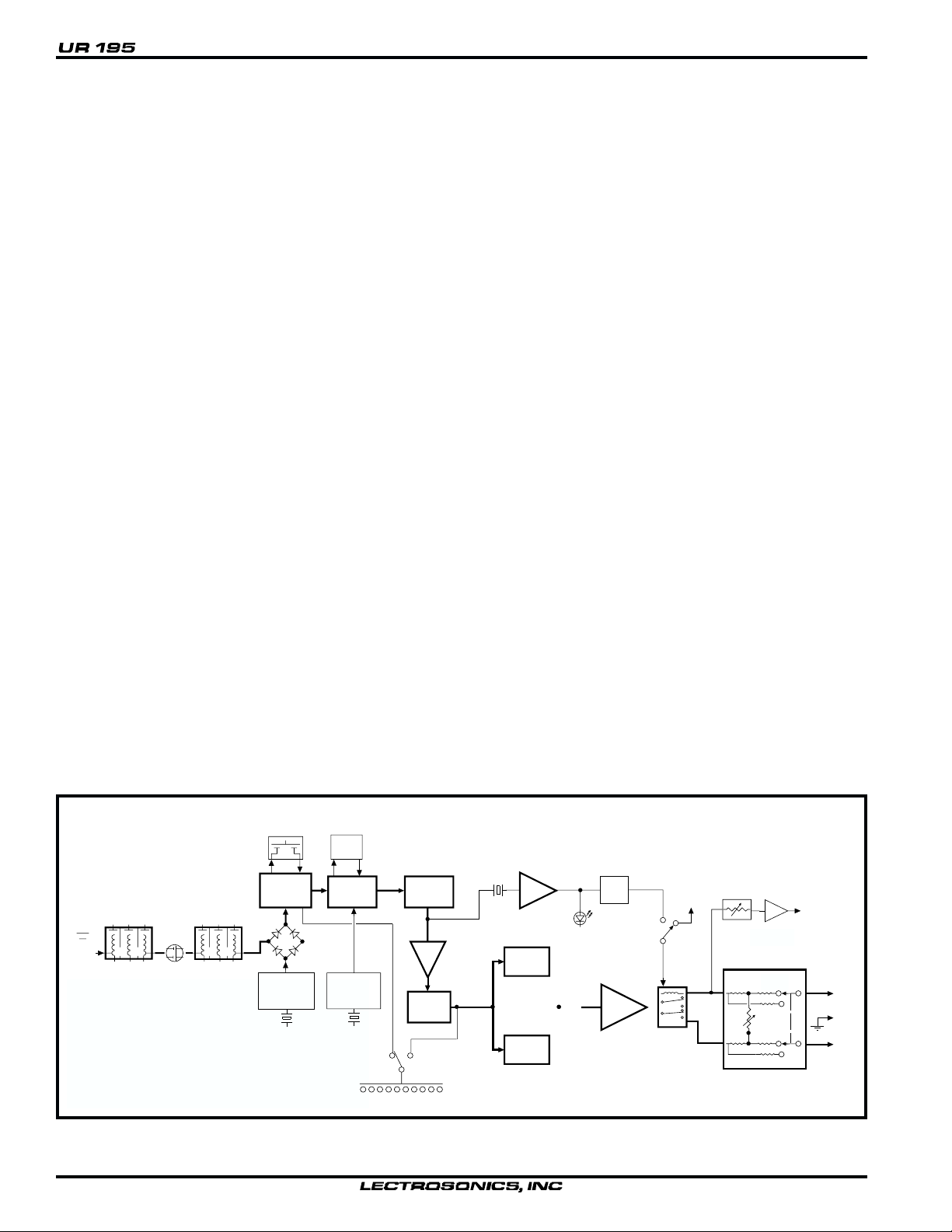
Figure 1 - UR195 Block Diagram
4
8 POLE
FILTER
10.7MHz IF
AMP
XTAL
1ST
HI-LEVEL
DIODE MIXER
455KHZ
BP
FILTER
2ND MIXER
&
IF AMP
XTAL
CONTROLLED
2ND
OSCILLATOR
MOD AUDIO
LED BARGRAPH METER
COUNTING
DETECTOR
AMP
32 kHZ
BLOCKING
FILTER
METER
MODE
32kHZ
AMP
2:1
EXPANDER
TREBLE
2:1
EXPANDER
BASS
PILOT
LED
PILOT
TONE
MUTE
AUDIO
AMP
ENABLE
PILOT
TONE
V+
DISABLE
MONITOR
LEVEL
AMP
OUTPUT LEVEL ADJUST
AND
RANGE SWITCH
HI
FIXED
HI
FIXED
MONITOR
OUT
XLR
OUT
3
1
2
Page 5

– – – –––
–
The audio signal leaves the Detector circuit and is fed through an
MONITOR
MOD
1mV
10uV
42
RF
1uV
36 30
PWR
100uV
121824
6
0dB
OFF
PILOT
AUDIO
OUTPUT
ON
amplifier to the 23 kHz Low Pass Filter where all the high frequency
noise (including the 32 kHz pilot tone) is filtered out. After the 23
kHz low pass filter, the signal is split into two parts via a 1 kHz low
pass filter and a 1 kHz high pass filter. The separated signals are
then processed in separate channels of the NE572 2:1 Expander.
Each channel of the 2:1 Expander is optimized for its respective
frequency band. The two outputs of the 2:1 Expander are then
summed in an op-amp summer and sent to the output amplifier as
one signal.
PILOT TONE MUTE (SQUELCH)
The 195 system utilizes a separate ultrasonic tone modulation of the
basic carrier to operate the receiver squelch. In the transmitter, a
32kHz tone is injected into the audio signal path just after the
compandor. The supersonic pilot tone is filtered out of the audio
signal immediately after the detector in the receiver so that it does
not influence the compandor or various gain stages.
The basic benefit of the pilot tone squelch system is that the receiver
will remain squelched (muted) until it receives the pilot tone from
the matching transmitter, even if a strong RF signal is present on the
FRONT PANEL CONTROLS AND FUNCTIONS
PWR LED
When lit, this LED indicates that power is applied to the UR195 and
adequate voltage is present to operate the unit.
PILOT LED
The audio output muting (squelch) function of the UR195 is
controlled by a 32kHz tone modulation of the RF carrier. The audio
output is muted until this tone is present. This LED will remain on
as long as the receiver audio is enabled by the pilot tone.
TRANSMITTER AUDIO LEVEL METER
When the meter function switch is in the Mod position, the modulation (audio level) of the incoming signal is indicated by a fast
responding LED strip. The strip is calibrated in 6dB steps over an
expanded scale (54dB) which provides an extremely accurate visual
“picture” of the signal dynamics, even at a distance away from the
receiver. Audio signal peaks easily exceed the response time of VU
meters, however, the LED strip is fast enough to track even brief
transients.
carrier frequency of the system. Once a pilot tone is received, the
receiver will remain open during all signal conditions.
The mute circuit drives a relay which physically disconnects the
output amplifier from the output. This provides complete muting of
the audio and the noise. The Pilot LED on the front panel will glow
when the pilot tone has enabled the receiver audio output.
OUTPUT LEVEL ADJUST AND RANGE SWITCH
The front panel Output control will adjust the audio output within
the range set by the VAR/FIX range switch (located on the back
panel.) In the VAR position the adjustment range is from –30dBm
to 0dBm, and the FIX position sets the audio output to a fixed
+8dBm with no front panel control.
POWER SUPPLY
The UR195 may be operated from the supplied CH12 adapter, or
from an external 12 to 18 VDC source. The power supply has a
built in Poly-Fuse to protect the unit. This fuse is self healing by
simply turning off the receiver for about 15 seconds.
audio output to feed recorders or external audio devices. The
Monitor jack is a mini stereo type with the same signal applied to
the tip and ring contacts. Stereo or mono headphones may be used
without any loss of volume or damaging the UR195.
POWER SWITCH
This slide switch, and its corrosponding LED indicator, switches the
receiver from Off to On. At turn on and off there is a delay built
into the receiver to allow various stages to stabilize before the audio
output is activated. This will prevent an audio “thump” when
powering up the receiver.
AUDIO OUTPUT
The front panel Output control will adjust the audio output within
the range set by the VAR/FIX range switch (located on the back
panel.) In the VAR position the adjustment range is from –30dBm
to 0dBm, and the FIX position sets the audio output to a fixed
+8dBm with no front panel control.
RF LEVEL INDICATORS
With the function switch in the RF position, the LED strip indicates
the level of the incoming RF signals. The LED strips are calibrated
to provide accurate indications from 1uV to 1mV. The LEDs are
highly visible from a distance, making antenna set up more accurate.
The LED strip is especially useful in trouble-shooting difficult
antenna installations.
MONITOR
This is a high quality audio output to drive a wide variety of
different types of headphones. It is also useable as a secondary
Rio Rancho, NM – USA
Figure 2 - UCR195 Front Panel
5
Page 6

REAR PANEL CONTROLS AND FUNCTIONS
AUDIO
VAR
FIX
AN T 12V DC IN
LECTROSONICS
1 2
3
EXTERNAL POWER JACK
The UR195 can be powered from external 12 to 18 Volts DC
applied directly to this jack, or conventional 110 VAC sources via
the supplied CH12 adapter. The UR195 is protected from reverse
polarity conditions with a diode bridge which allows external DC to
be applied without regard to polarity. If an external positive ground
power source is used, the case of the unit must be left floating and
not tied to the same common as the positive ground supply. If the
UCR195 common is tied to the common of the positive ground
supply, there are protection circuits built into the unit that will shut
the unit down before any harm is done.
AUDIO OUTPUT XLR JACK
This jack is a standard 3 pin XLR connector since this is the most
commonly used type of connector. Audio High (+) is on pin 3,
Audio Low (–) is on pin 2, and audio Common (Gnd) is pin 1.
RANGE SWITCH
The range is set by the VAR/FIX range switch (located on the back
panel.) In the VAR position the adjustment range is from –30dBm
to 0dBm, and the FIX position sets the audio output to a fixed
+8dBm with no front panel control.
ANTENNA CONNECTOR
This is a standard 50 Ohm BNC type jack for the RF input to the
receiver.
Figure 3 - UR195 Rear Panel
6
Page 7

ANTENNA USE AND PLACEMENT
Position the antenna so that it is more than 3 or 4 feet from large
metal surfaces. If this is not possible, try to position the antenna so
that it is as far away from the metal surface as is practical. You can
also let the metal surface work for you by aligning the antenna
perpendicular to the surface. This will provide a ground plane for
the antenna. It is also good to position the receiver and/or antenna
so that there is a direct “line of sight” between the transmitter and
the receiver antenna. In situations where the operating range is less
than about 50 feet, the antenna positioning is much less critical.
A wireless transmitter sends a radio signal out in all directions. This
signal will often bounce off nearby walls, ceilings, etc. and a strong
reflection can arrive at the receiver antenna along with the direct
signal. If the direct and reflected signals are out of phase with each
other a cancellation may occur. The result would be a “drop-out.”
A drop-out sounds like either audible noise (hiss), or in severe cases,
may result in a complete loss of the carrier and the sound when the
transmitter is positioned in certain locations in the room. Moving
the transmitter even a few inches will change the sound of the hum
or hiss, or eliminate it. A drop-out situation may be either better or
REFLECTIVE SURFACE
worse as a crowd fills and/or leaves the room, or when the transmitter or receiver is operated in a different location.
The UR195 receiver offers a sophisticated front end design which
overcomes drop-out problems in almost any imaginable situation.
At UHF frequencies, drop outs (noise ups) are often so brief that
they sound like a "click" rather than a burst of noise. Generally,
drop outs are virtually non-existent within several hundred feet of
operating range. In the event, however, that you do encounter a
dropout problem, first try moving the antenna at least 2 or 3 feet
from where it was. This may alleviate the drop-out problem. If
drop-outs are still a problem, try moving the antenna to an entirely
different location in the room or move the antenna in closer to the
transmitter location.
Lectrosonics transmitters radiate power very efficiently, and the
receivers are very sensitive. This reduces drop-outs to an insignificant level. If, however, you do encounter drop-outs frequently, call
the factory or consult your dealer. There is probably a simple
solution.
TRANSMITTER
PHASE
CANCELLATION
D
I
N
D
I
R
E
C
T
S
I
G
N
A
L
L
A
N
G
I
S
T
C
E
R
I
DIRECT SIGNAL
RECEIVER
INDIRECT SIGNAL
MULTI-PATH DROPOUT
Figure 4 - Drop-outs
Rio Rancho, NM – USA
7
Page 8

511
511
OPERATING INSTRUCTIONS
MONITOR
LEVEL
AMP
3
2
1
HI
FIXED
HI
FIXED
50
1k
50
MUTE
RELAY
1. Connect the power cord.
2. Attach the antenna.
3. Connect the audio cable to the audio output XLR.
4. Set the front panel Audio Output Level control to minimum and set the Power switch to On. Check to see that the front
panel Power LED lights up.
5. Adjust the transmitter gain. THIS IS PERHAPS THE MOST IMPORTANT STEP IN THE SET UP PROCEDURE. See
your transmitter manual (Operating Instructions section) for details on how to adjust the transmitter gain. In general, adjust
the transmitter gain so that the voice peaks will cause the 0dB LED on the front of the receiver to light on the loudest peak
audio levels. This will result in the best possible signal to noise ratio for the system without causing overload distortion.
6. Adjust the Audio Output control according to the type of input on your equipment. The Range switch (located on the back
panel) sets the adjustment range of the front panel Audio Output control and has two positions.
VAR: Allows an adjustment from –30dBm to 0dBm
FIX: Sets the audio output to a fixed +8dBm with no
front panel control.
The input levels of different cameras, VCRs, and PA equipment vary, which may require that you set the Audio Output
control to an intermediate position. Try different settings and listen to the results. If the output of the receiver is too high,
you may hear distortion or a loss of the natural dynamics of the audio signal. If the output is too low, you may hear steady
noise (hiss) along with the audio. The UR195 audio output is designed to drive any audio input device from microphone
level to +8dBm line level.
Note:
When using the +8 dBm FIX position of the output range switch, do not ground pin 2 or pin 3 of the XLR output! The
output impedance is only 50 Ohms (unbalanced) when in the FIX position and this is not enough to isolate the audio amplifier
from a short to ground. Distortion will result.
UR195 Simplified Audio
Output Circuit
UR195 REPLACEMENT PARTS and ACCESSORIES
Part No. Description
A-500S UHF Rubber Duck Antenna, straight connector
A-500RA UHF Rubber Duck Antenna, right angle connector
32251 Velcro mounting strips
35753 Zippered, padded vinyl system pouch
CH12 AC Power Adapter, 110V input, 12VDC output
8
Page 9

TROUBLESHOOTING
POWER SUPPLY AND FUSE
LEDs not lit or dimly lit
AC power cord disconnected.
External power supply disconnected or inadequate.
Main power supply fuse tripped. Turn the receiver off, remove the cause of the overload and turn the
receiver back on.
PILOT TONE SQUELCH
The PILOT indicator lamp on the front panel lights up to indicate that the audio has been turned on at the
transmitter, and that the audio output on the receiver is enabled. When the lamp is on, the audio is enabled.
When the lamp is off, the audio is muted.
PILOT lamp on, but no sound
Audio output cable bad or disconnected. Try monitoring at the headphone output on the front panel.
The headphone output signal is taken just ahead of the output transformer.
Audio Output level set too low.
PILOT lamp does not come on when transmitter audio switch is turned on
It takes several seconds for the relay to actuate the PILOT lamp. Turn the transmitter power and audio
switches on and wait 5 to 10 seconds for the lamp to come on.
ANTENNAS AND RF SIGNAL STRENGTH
RF Level is weak.
Antenna is disconnected or there is a bad connection
Antenna may need to be moved or re-oriented
Improper length of antenna, or wrong antenna. UHF whip antennas are generally about 5 to 6 inches
long. UHF helical antennas may be shorter, but are often less efficient.
AUDIO SIGNAL QUALITY
Poor signal to noise ratio
Transmitter gain set too low
Noise may not be in wireless system. Mute the audio signal at the transmitter and see if noise remains. If the
noise remains, then turn the power off at the transmitter and see if it remains. If the noise is still present, then
the problem is not in the transmitter.
If noise is still present when the transmitter is turned off, try lowering the audio output level on the UR195
rear panel and see if the noise lowers correspondingly. If the noise remains, the problem is not in the
receiver.
Receiver output is too low for the input of the device it is feeding. Try increasing the output level of the
UR195 and lowering the input gain on the device the UR195 is feeding.
Distortion
Transmitter input gain too high. Check and/or re-adjust input gain on transmitter according to the LEDs on
the transmitter and then verify the setting with the transmitter audio level LED strip on the UR195 front
panel.
Audio output level too high for the device the UR195 is feeding. Lower the output level of the UR195.
Rio Rancho, NM – USA
9
Page 10

SERVICE AND REPAIR
If your system malfunctions, you should attempt to correct or isolate the trouble before concluding that the
equipment needs repair. Make sure you have followed the setup procedure and operating instructions. Check
out the inter-connecting cords and then go through the TROUBLE SHOOTING section in the manual
We strongly recommend that you do not try to repair the equipment yourself and do not have the local repair
shop attempt anything other than the simplest repair. If the repair is more complicated than a broken wire or
loose connection, send the unit to the factory or an authorized service center equipped to service the UCR195
receivers. Don’t attempt to adjust any controls inside the units. Once set at the factory, the various controls
and trimmers do not drift with age or vibration and never require readjustment. There are no adjustments
inside that will make a malfunctioning unit start working.
LECTROSONICS service department is equipped and staffed to quickly repair your equipment. In-warranty
repairs are made at no charge in accordance with the terms of the warranty. Out of warranty repairs are
charged at a modest flat rate plus parts and shipping. Since it takes almost as much time and effort to determine what is wrong as it does to make the repair, there is a charge for an exact quotation. We will be happy to
quote approximate charges by phone for out of warranty repairs.
RETURNING UNITS FOR REPAIR
You will save yourself time and trouble if you will follow the steps below:
A. DO NOT return equipment to the factory for repair without first contacting us by letter or by phone. We
need to know the nature of the problem, the model number and the serial number of the equipment. We also
need a phone number where you can be reached 8 am to 4 pm (Mountain Standard Time).
B. After receiving your request, we will issue you a return authorization number (R.A.). This number will help
speed your repair through our receiving and repair departments. The return authorization number must be
clearly shown on the outside of the shipping container.
C. Pack the equipment carefully and ship to us, shipping costs prepaid. If necessary, we can provide you with
the proper packing materials. UPS is usually the best way to ship the units. Heavy units should be “doubleboxed” for safe transport.
D. We also strongly recommend that you insure the equipment, since we cannot be responsible for loss of or
damage to equipment that you ship. Of course, we insure the equipment when we ship it back to you.
Mailing address: Shipping address: Telephones:
Lectrosonics, Inc. Lectrosonics, Inc. (505) 892-4501
PO Box 15900 581 Laser Rd. (800) 821-1121
Rio Rancho, NM 87174 Rio Rancho, NM 87124 FAX: (505) 892-6243
USA USA
10
Web: http://www.lectrosonics.com email: sales@lectrosonics.com
Page 11

SPECIFICATIONS AND FEATURES
Receiver
Operating Frequencies:
Receiver Type:
Frequency Stability:
Front end selectivity:
IF Selectivity:
IF Frequency:
IF bandwidth:
Sensitivity
20 dB Sinad:
60 dB Quieting:
Squelch quieting:
AM rejection:
Modulation acceptance:
Image and spurious
rejection:
Third order intercept:
FM Detector:
Antenna input:
Audio outputs
Rear Panel XLR:
Monitor out:
Front Panel Controls
and Indicators:
Rear Panel
Connectors:
Rear Switch:
Power Options:
470 to 608 MHz, crystal controlled
Dual conversion, superheterodyne
±0.002 %
-22 dB at ±4 MHz
>90 dB at ±300 kHz (10.7 IF)
10.7 MHz (1st IF); 455 kHz (2nd IF)
±150 kHz at ½ power points
0.63 uV (-111 dBm), A weighted
1.0 uV (-107 dBm), A weighted
Greater than 125 dB
Greater than 60 dB, 2uV to 1 Volt
(Undetectable after processing)
±75 kHz
> 98 dB
–5 dBm
Digital Pulse Counting Detector
BNC female; 50 Ohm impedance
Nominal 600 Ohm Balanced
VAR: Variable –50 dBm to –30
dBm; FIXED: +8 dBm line level
Front panel 3.5mm stereo mini jack
– high level output for stereo or
mono phones @ 32 Ohms or higher
– can be used as a high quality
audio output.
Power on/off switch and LED; Dual
function 10 segment LED level
display; Pilot tone indicator;
Monitor output jack and Level
control
XLR audio output jack;
External 12VDC input
Audio Output Range:
VAR/FIXED
12V DC, 1.7 Watts (140 mA)
System (UR195 receiver with UM195 transmitter)
Audio Processor:
Total Harmonic Distortion
1 kHz:
30 Hz to 20 kHz:
Signal/Noise ratio:
Frequency Response:
Dual band compandor with no
pre-emphasis/de-emphasis
< 0.45% (60 kHz deviation)
< 1% (30 kHz deviation)
60 dB, at 0.63 uV (-111 dBm)
signal input, A-weighted
109 dB for full quieting, A
weighted
±1 dB, 30 Hz to 21 kHz,
400 Hz reference, 30 kHz
deviation
Weight:
Dimensions:
16 ozs. (with batteries)
3.2” wide x 1.22” high x 5.1” deep
Rio Rancho, NM – USA
11
Page 12

LIMITED ONE YEAR WARRANTY
The equipment is warranted for one year from date of purchase against defects in materials or
workmanship provided it was purchased from an authorized dealer. This warranty does not cover
equipment which has been abused or damaged by careless handling or shipping. This warranty does
not apply to used or demonstrator equipment.
Should any defect develop, we will, at our option, repair or replace any defective parts without charge
for either parts or labor. If we cannot correct the defect in your equipment, we will replace it at no
charge with a similar new item. We will pay for the cost of returning your merchandise to you.
This warranty applies only to items returned to us, shipping costs prepaid, within one year from the
date of purchase.
This warranty gives you specific legal rights. You may have additional legal rights which vary from
state to state.
LECTROSONICS, INC.
581 LASER ROAD
RIO RANCHO, NM 87124 USA
12
July 6, 1999
 Loading...