

Page 1

UHF and VHF
Rack Mount Multi Channel Systems
OPERATING INSTRUCTIONS
and trouble-shooting guide
RDM4, SDM4, SDM4D
UMC190, UMC195, UMC195D
LECTROSONICS, INC.
Rio Rancho, NM
www.lectrosonics.com
Page 2

UHF and VHF
INTRODUCTION
The RDM4, SDM4, SDM4D, UMC190, UMC195 and UMC195D systems are high
quality, multi-channel wireless microphone systems designed for sound stage,
studio, and theater applications. Multi-channel problems such as interaction of
receivers, intermodulation and desensitization, etc. have been eliminated through
creative engineering and superior design. The integral RF/Power distribution
module provides convenience of operation from a common antenna system and
power supply without degrading the performance of the receivers. In fact, the
additional RF filtering in the distribution module actually improves the already
outstanding selectivity of the receivers.
This manual covers the following systems:
Multi-Channel System Installed Receivers
UMC190 frame with UHF RF/power distribution ....................UR190, UCR190
UMC195 frame with UHF RF/power distribution ....................UCR195 only
UMC195D frame with UHF RF/power distribution .................UCR195D only
SDM4 frame with VHF RF/power distribution......................... CR175, CR187
SDM4D frame with VHF diversity RF/power distribution ........ DR175 only
RDM4 frame with VHF RF/power distribution ........................R175 only
TABLE OF CONTENTS
INTRODUCTION .................................................................................................. 2
GENERAL TECHNICAL DESCRIPTION ............................................................ 3
ASSEMBLY and INSTALLATION ......................................................................... 4
FRONT PANEL DESCRIPTION........................................................................... 5
REAR PANEL DESCRIPTION ............................................................................. 5
TROUBLESHOOTING ......................................................................................... 6
ACCESSORIES .................................................................................................... 6
ANTENNA USE AND PLACEMENT .................................................................... 7
SPECIFICATIONS ................................................................................................ 8
SERVICE AND REPAIR ....................................................................................... 9
RETURNING UNITS FOR REPAIR ..................................................................... 9
WARRANTY ......................................................................................... Back cover
2
Page 3
Rack Mount Multi-Channel Systems
GENERAL TECHNICAL DESCRIPTION
The Multi-Channel Wireless Systems consist of two sub-systems; the frame which contains the receivers and the
receiver mounting hardware, and the RF/power distribution module.
The RF/power distribution module is the heart of the Multi-Channel Wireless System. Selective filtering in the front
end of the RF section attenuates out-of-band RF signals preventing intermodulation and front end overload. Following the filters is a low noise, low gain RF amplifier designed to evenly compensate for splitter losses in the stage that
follows. A precision splitter/isolator divides the RF signal into four isolated signals preventing spurious RF coupling
between receivers. The splitter/isolator is termination independent which prevents mismatched or disconnected RF
outputs from affecting the other receivers.
Power is supplied to the RF/power distribution module from an external DC power supply module. This keeps AC
hum problems to a minimum. All power circuits are protected by internal auto-reset fuses in the RF/power distribution module. Should the power to one receiver fail, the others will continue to operate.
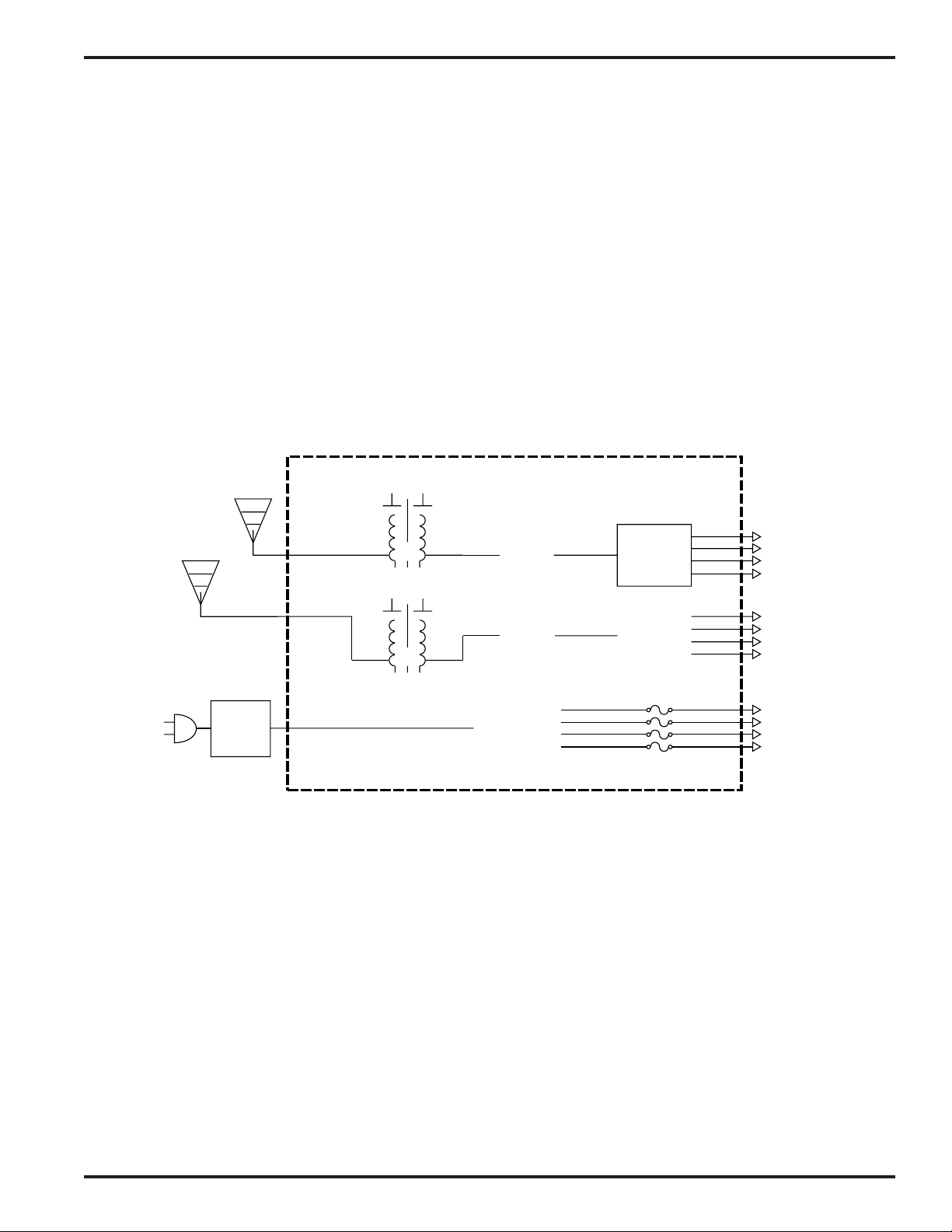
Diversity RF/Power Distribution Module
A
ANTENNA
RF FILTERING & DISTRIBUTION
B
ANTENNA
POWER
SUPPLY
FRONT END
FILTERS
RF
AMP
RF
AMP
REGULATOR
POWER SUPPLY & DISTRIBUTION
SPLITTER
&
ISOLATOR
RF to
Receivers
SPLITTER
&
ISOLATOR
POLYFUSES
12V DC
Power to
Receivers
Rio Rancho, NM – USA
3
Page 4

UHF and VHF
ASSEMBLY and INSTALLATION
Assembly of the unit consists of installing the receivers into the frame and connecting the antenna and power leads
to each receiver. This is only necessary if the unit was purchased without any receivers. If the unit is purchased with
receivers, they are installed at the factory before shipment.
IMPORTANT - The receivers installed in the unit must fall between the frequencies indicated on the SERIAL/FREQUENCY
label. Serious signal loss results if the receivers are outside the RF pass-band.
INSTALLING THE RECEIVERS
1. Remove the U-channel wire cover by completely removing the four counter-sunk phillips head screws from the top
of the unit. Underneath the U-channel wire cover is a rectangular metal rod held down by five counter-sunk
phillips head screws. Loosen these five screws five to seven turns (it’s not necessary to remove them completely.)
2. Before installing the receivers, be sure to record the serial numbers and frequencies. This information is printed
on the side panel labels which won’t be visible after installation.
3. If your receivers have the antenna jack(s) on the front panel, route the antenna leads through the slots on the front
of the frame before mounting the receivers. Be sure to route the wires under the rectangular metal rod.
4. Insert the first receiver into the slot nearest to the power switch by sliding it under the wiring harness and the
rectangular metal rod. Be sure the front panel of the receiver is fully inserted into the cutout on the inside of the
front panel. Install the remaining receivers in the same manner.
5. Secure the receivers into the frame by tightening the five counter-sunk phillips head screws in the rectangular
metal rod. Don’t overtighten!
6. Attach the antenna leads to each receiver. Diversity units have dual antenna cables for each receiver. They are
marked with “A” and “B” which correspond to the “A” and “B” antenna inputs on the Diversity RF/power distribution
module. Each diversity receiver must get an “A” lead and a “B” lead or the benefits of diversity reception will be
lost. Non diversity units will have only one antenna lead per receiver.
7. Attach one power lead to the 12V DC IN jack on the rear of each receiver.
8. Dress the antenna and power wires so that the bundle is as flat as possible and to the rear of the rectangular
metal rod. For receivers with the antenna jacks on the front, be sure the antenna wires are routed under the
rectangular metal rod. Carefully place the U-channel wire cover over the wiring bundle and press down to see if it
will lay flat without pinching any of the wires underneath. It may be necessary to re-dress the wires to accomplish
this.
9. Start the four phillips head screws and tighten them slowly while watching the wires to be sure none are pinched.
INSTALLING THE ASSEMBLED UNIT
1. Mount the assembled frame into the rack, connect the antenna(s) to the Antenna input(s) and the PS50 power
supply to the 12VDC jack on the rear of the RF/power distribution module.
4
Page 5

Rack Mount Multi-Channel Systems
FRONT PANEL DESCRIPTION
The front panel contains only one control - the Power switch.
Many different receivers can be mounted within the frame. Please refer to the separate receiver manual for a
description of the controls and features of each individual receiver.
Multi Channel System Front View (UMC190 with UR190 receivers shown)
REAR PANEL DESCRIPTION
RF/POWER DISTRIBUTION MODULE
SERIAL/FREQUENCY LABEL
This label indicates the serial number of the DM4 module. It also indicates the RF pass-band of the unit.
IMPORTANT - The receivers installed in the unit must fall between the frequencies indicated on the label. Serious
signal loss results if the receivers are outside the RF pass-band.
ANTENNA
Diversity units will have an “A” and a “B” antenna jack. This is a standard 50 Ohm BNC-F. Antennas connected to
these jack will have their signal filtered, amplified and distributed to each receiver via the BNC output plugs.
12 VDC - DC
Power input jack. Any positive DC supply from 12 to 24 VDC may be used. The jack accepts standard coaxial power
plugs with center pin positive. The polarity is marked on the rear of the unit. DC power applied to this jack will be
distributed to the four coaxial power plugs that power the individual receivers.
RF Output DC Output
Antenna In 12 VDC In to Receiver to Receiver
Multi Channel System Rear View (RDM4 with R175 Receivers shown)
Rio Rancho, NM – USA
5
Page 6

UHF and VHF
TROUBLESHOOTING
SYMPTOM POSSIBLE CAUSE
NO POWER LEDs OR AUDIO 1) Power switch in the OFF position. Switch to ON.
POWER AND MODULATION LEDs ON,
BUT NO AUDIO
POWER LEDs ON, NO MODULATION LEDs 1) Transmitters not on or in mute position. Check transmitters.
POOR SIGNAL/NOISE OR DROPOUTS 1) Antenna leads not connected. Check antenna(s).
1) No audio connection to recorder or mixer.
Check connections.
2) Transmitters have dead batteries, check batteries.
2) Main antenna(s) improperly connected. Check antenna(s).
3) Antenna “blocked” or in poor RF location. Try repositioning the
antenna(s).
4) Transmitter modulation improperly set. Check mod levels.
ACCESSORIES
PS50 1.2 Amp regulated power supply for 19" rack mount systems
A-RG2 RF coaxial cable assembly, 2ft length, BNC-BNC
A-RG15 RF coaxial cable assembly, 15ft length, BNC-BNC
A-GPU UHF Ground plane antenna
A-Y3U UHF Directional yagi antenna
A-185COAX Remote folded dipole VHF antenna
A-200 Remote dipole VHF antenna, dual whips, aluminum base
6
Page 7

Rack Mount Multi-Channel Systems
T
ANTENNA USE AND PLACEMENT
Position the antennas so that they are not within 3 or 4 feet of large metal surfaces. If this is not possible, try to
position the antennas so that they are as far away from the metal surface as is practical. It is also good to position
the receiver so that there is a direct “line of sight” between the transmitter and the receiver antenna. In situations
where the operating range is less than about 50 feet, the antenna positioning is much less critical.
A wireless transmitter sends a radio signal out in all directions. This signal will often bounce off nearby walls, ceilings, etc. and a strong reflection can arrive at the receiver antenna along with the direct signal. If the direct and
reflected signals are out of phase with each other a cancellation may occur. The result would be a “drop-out.” A
drop-out sounds like either audible noise (hiss), or in severe cases, may result in a complete loss of the carrier and
the sound when the transmitter is positioned in certain locations in the room. A drop-out normally sounds like “hum”
or “hiss.” Moving the transmitter even a few inches will change the sound of the hum or hiss, or eliminate it. A dropout situation may be either better or worse as the crowd fills and/or leaves the room, or when the transmitter or
receiver is operated in a different location.
Lectrosonics receivers offer a sophisticated design which overcomes drop-out problems in almost any imaginable
situation. In the event, however, that you do encounter a dropout problem, first try moving the antenna at least 3 or 4
feet from where it was. This may alleviate the drop-out problem on that antenna. If drop-outs are still a problem, try
moving the antenna to an entirely different location in the room or moving the antennas in closer to the transmitter
location. By observing the LEDs on the front panel, you can determine which antenna is suffering weak signals.
Lectrosonics transmitters radiate power very efficiently, and the receivers are very sensitive. This reduces drop-outs
to an insignificant level. If, however, you do encounter drop-outs frequently, call the factory or consult your dealer.
There is probably a simple solution.
RANSMITTER
PHASE
CANCELLATION
REFLECTIVE SURFACE
INDIRECT SIGNAL
DIRECT SIGNAL
DIRECT SIGNAL
INDIRECT SIGNAL
LECTROSONICS
Rio Rancho, New Mexico – U.S.A.
POWER
Multipath Dropouts
Rio Rancho, NM – USA
7
Page 8

UHF and VHF
SPECIFICATIONS
RF Gain: 0.5 to 1.5dB
Bandwidth
VHF: Factory tunable to any 4 MHz band from 150 to 216MHz.
Specified at time of order.
UHF: Factory tunable to any 18MHz band from 470 to 608MHz.
Specified at time of order.
RF Outputs
Standard: Four outputs, 50 Ohm, BNC
Diversity: Eight outputs, 50 Ohm, BNC
Isolation: 25dB min, any output to any output
Any output can be open, shorted, or terminated without affecting
other outputs.
Splitter type: Wilkinson 1/4 wave
Filtering:
UHF: Two pole ceramic filter per antenna
VHF: Two section helical resonator per antenna
Noise figure
VHF: 3.5dB
UHF: 3.5dB
Third Order Intercept: +19 dBm
Power Input: +12 to +24VDC
Power Consumption:
Standard: 70mA
Diversity: 140mA
Connectors:
RF: BNC
Power Output: 5.5mm OD/2mm ID coaxial power jack
Short Circuit Protection: Auto-reset thermal fuses
Construction: Machined aluminum panels, housings, and mechanical parts.
Dimensions: 19" wide, 1.75" high, 6.5" deep
Weight: 5 lbs including 4 receivers
Specifications subject to change without notice.
8
Page 9

Rack Mount Multi-Channel Systems
SERVICE AND REPAIR
If your system malfunctions, you should attempt to correct or isolate the trouble before concluding that the equipment
needs repair. Make sure you have followed the setup procedure and operating instructions. Check out the interconnecting cords and then go through the TROUBLE SHOOTING section in the manual
We strongly recommend that you do not try to repair the equipment yourself and do not have the local repair shop
attempt anything other than the simplest repair. If the repair is more complicated than a broken wire or loose connection, send the unit to the factory for repair and service. Don’t attempt to adjust any controls inside the units.
Once set at the factory, the various controls and trimmers do not drift with age or vibration and never require readjustment. There are no adjustments inside that will make a malfunctioning unit start working.
LECTROSONICS’ service department is equipped and staffed to quickly repair your equipment. In warranty repairs
are made at no charge in accordance with the terms of the warranty. Out of warranty repairs are charged at a
modest flat rate plus parts and shipping. Since it takes almost as much time and effort to determine what is wrong
as it does to make the repair, there is a charge for an exact quotation. We will be happy to quote approximate
charges by phone for out of warranty repairs.
RETURNING UNITS FOR REPAIR
You will save yourself time and trouble if you will follow the steps below:
A. DO NOT return equipment to the factory for repair without first contacting us by letter or by phone. We need to
know the nature of the problem, the model number and the serial number of the equipment. We also need a phone
number where you can be reached 8 am to 4 pm (Mountain Standard Time).
B. After receiving your request, we will issue you a return authorization number (R.A.). This number will help speed
your repair through our receiving and repair departments. The return authorization number must be clearly shown
on the outside of the shipping container.
C. Pack the equipment carefully and ship to us, shipping costs prepaid. If necessary, we can provide you with the
proper packing materials. UPS is usually the best way to ship the units. Heavy units should be “double-boxed” for
safe transport.
D. We also strongly recommend that you insure the equipment, since we cannot be responsible for loss of or damage
to equipment that you ship. Of course, we insure the equipment when we ship it back to you.
Mailing address: Shipping address: Telephones:
Lectrosonics, Inc. Lectrosonics, Inc. Regular: (505) 892-4501
PO Box 15900 581 Laser Rd. Toll Free (800) 821-1121
Rio Rancho, NM 87174 Rio Rancho, NM 87124 FAX: (505) 892-6243
USA USA
World Wide Web: http://www.lectrosonics.com Email: sales@lectrosonics.com
Rio Rancho, NM – USA
9
Page 10

LIMITED ONE YEAR WARRANTY
LIMITED ONE YEAR WARRANTY
The equipment is warranted for one year from date of purchase against defects in
materials or workmanship provided it was purchased from an authorized dealer. This
warranty does not cover equipment which has been abused or damaged by careless
handling or shipping. This warranty does not apply to used or demonstrator equipment.
Should any defect develop, Lectrosonics, Inc. will, at our option, repair or replace any
defective parts without charge for either parts or labor. If Lectrosonics, Inc. cannot
correct the defect in your equipment, it will be replaced at no charge with a similar new
item. Lectrosonics, Inc. will pay for the cost of returning your equipment to you.
This warranty applies only to items returned to Lectrosonics, Inc. or an authorized
dealer, shipping costs prepaid, within one year from the date of purchase.
This Limited Warranty is governed by the laws of the State of New Mexico. It states the
entire liablility of Lectrosonics Inc. and the entire remedy of the purchaser for any
breach of warranty as outlined above. NEITHER LECTROSONICS, INC. NOR
ANYONE INVOLVED IN THE PRODUCTION OR DELIVERY OF THE EQUIPMENT
SHALL BE LIABLE FOR ANY INDIRECT, SPECIAL, PUNITIVE, CONSEQUENTIAL,
OR INCIDENTAL DAMAGES ARISING OUT OF THE USE OR INABILITY TO USE
THIS EQUIPMENT EVEN IF LECTROSONICS, INC. HAS BEEN ADVISED OF THE
POSSIBILITY OF SUCH DAMAGES. IN NO EVENT SHALL THE LIABILITY OF
LECTROSONICS, INC. EXCEED THE PURCHASE PRICE OF ANY DEFECTIVE
EQUIPMENT.
This warranty gives you specific legal rights. You may have additional legal rights which
vary from state to state.
LECTROSONICS, INC.
581 LASER ROAD
RIO RANCHO, NM 87124 USA
www.lectrosonics.com
July 18, 2001
 Loading...