

Page 1

UMC 16A
RF DISTRIBUTION SYSTEM
OPERATING INSTRUCTIONS
and trouble-shooting guide
Rio Rancho, NM, USA
www.lectrosonics.com
Page 2

INTRODUCTION
The UMC16 multi-coupler combines ceramic filtering with low noise, high intercept
point RF distribution to provide outstanding performance and flexibility. Up to
eight diversity receivers or up to 16 non-diversity receivers can be utilized in up to
a 50MHz passband.
The UMC16 can be powered by 110V AC for stage, studio or installed system
applications, or from DC power for field operation.
Table of Contents
INTRODUCTION..................................................................................... 2
GENERAL TECHNICAL DESCRIPTION .............................................. 3
FRONT PANEL DESCRIPTION ............................................................. 3
REAR PANEL DESCRIPTION ............................................................... 4
PHANTOM POWER JUMPERS ............................................................. 4
ANTENNA USE AND PLACEMENT ..................................................... 5
SPECIFICATIONS .................................................................................. 6
SERVICE AND REPAIR ......................................................................... 7
RETURNING UNITS FOR REPAIR ....................................................... 7
WARRANTY ........................................................................... Back cover
2
Page 3
GENERAL TECHNICAL DESCRIPTION
A universal power supply provides operation world-wide. An LED on the front panel verifies the presence of power
to the internal circuit board.
Selective filtering ahead of the low noise, high intercept RF amplifiers reduces intermodulation problems caused by
overload in the RF amplifiers. The filters provide a factory settable bandwidth of 16 to 50MHz.
Note: The frequency range and bandwidth is set at the factory and can be found by the serial number on the rear
of the unit.
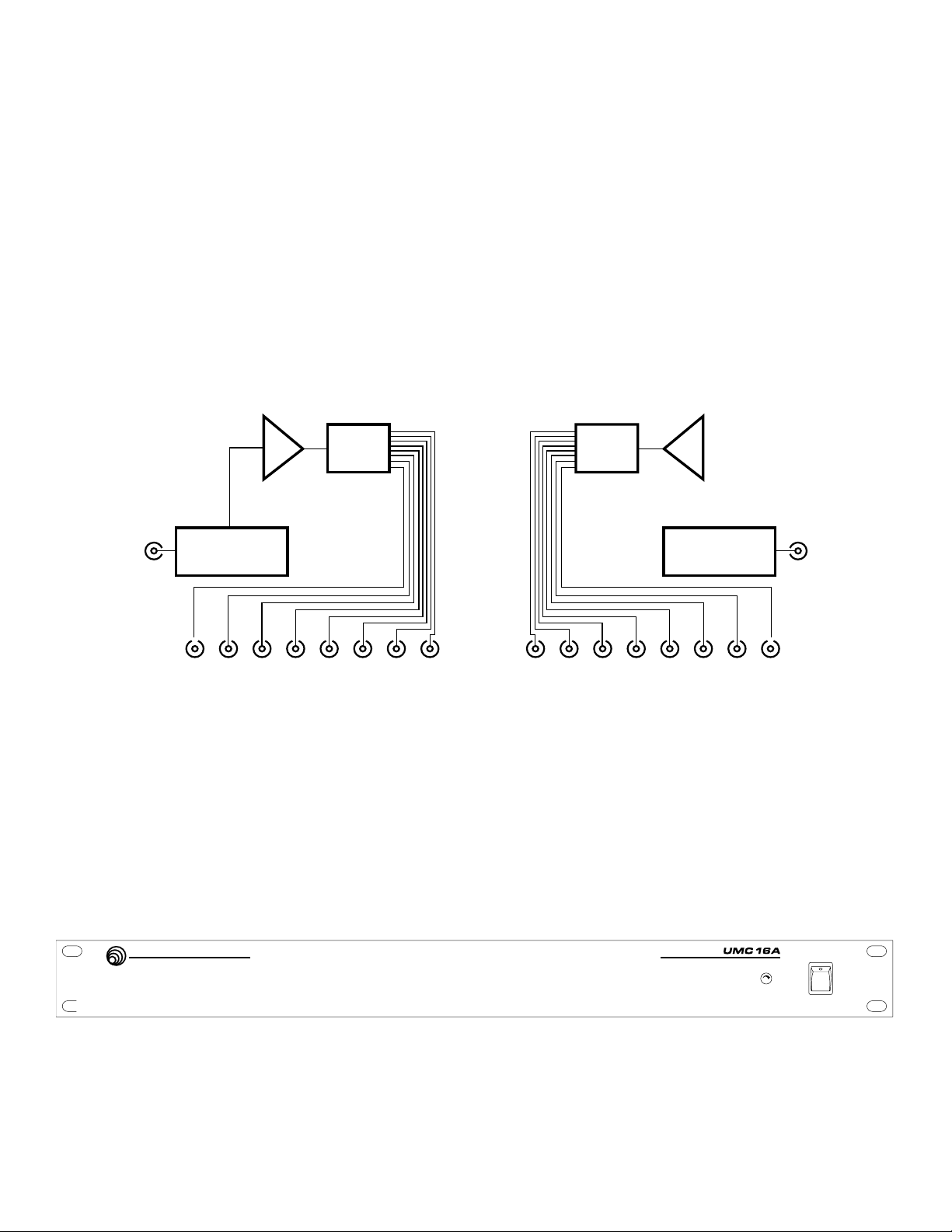
Each antenna input feeds a ceramic filter assembly. The antenna outputs are coupled to the filter assemblies via
“strip lines” (1/4 wave transmission lines) built onto the circuit board, which function as RF power dividers.
Each ceramic filter module feeds eight outputs on the rear panel.
Strip Line
RF Power
Divider
Low Noise
Amp
A
IN IN
Ceramic Resonator
Filter
A OUT
Strip Line
RF Power
Divider
Low Noise
Amp
Ceramic Resonator
B OUT
Filter
B
Figure 1 - UMC16a Block Diagram
FRONT PANEL DESCRIPTION
LECTROSONICS
Rio Rancho, New Mexico – U.S.A.
Figure 2 - UMC16a Front Panel
POWER
Main power switch for the UMC16 with indicator LED.
16 Channel UHF Multi-Coupler
POWER
3
Page 4

REAR PANEL DESCRIPTION
UMC16A
S/N 0000
000-111 MHz
12V DC IN
400MA MAX
RF OUT
100 - 240 VAC
10 WATTS
ANT B
RF OUT
Figure 3 - UMC16a Rear Panel
ANT A / ANT B
RF input jacks. These are standard BNC, quarter-turn twist lock connectors. Each antenna
jack is completely separate from the other.
RF OUT
RF output to receiver antenna jack(s). Each group of RF outputs is completely separate from the other.
12V DC IN
Alternate power input jack. The UMC16 can accept any DC voltage from +11 to +14.V DC.
110V AC Power Input Jack
This is a standard 3-prong AC power jack. The unit can accept any voltage in the range of
100 to 240 VAC at 10 Watts.
PHANTOM POWER JUMPERS
NOTE: These jumpers are ONLY to be used when the Lectrosonics UFM50 filter/amp module is being
powered through the antenna input jacks on the UMC16A multicoupler.
ANT A
1. Unplug the power cord and place the UMC16A so that the front panel faces away from you. Remove the cover
from the UMC16A (12 screws).
2. Locate the socket for antenna B (ANT B) on the circuit board next to the power wires (see photo below left).
Install the jumper to enable DC power on the ANT B connector.
Jumper for ANT B
Input Connector
Jumper for ANT A
Input Connector
3. On the other end of the unit, locate the jumper for antenna A (ANT A). (See photo above right.)
4. Install the jumper to enable DC power on the ANT A connector.
4
Page 5

ANTENNA USE AND PLACEMENT
T
Position the antennas so that they are not within 3 or 4 feet of large metal surfaces. If this is not possible, try to
position the antennas so that they are as far away from the metal surface as is practical. It is also good to
position the receiver so that there is a direct “line of sight” between the transmitter and the receiver antenna. In
situations where the operating range is less than about 50 feet, the antenna positioning is much less critical.
A wireless transmitter sends a radio signal out in all directions. This signal will often bounce off nearby walls,
ceilings, etc. and a strong reflection can arrive at the receiver antenna along with the direct signal. If the direct and
reflected signals are out of phase with each other a cancellation may occur. The result would be a “drop-out.” A
drop-out sounds like either audible noise (hiss), or in severe cases, may result in a complete loss of the carrier
and the sound when the transmitter is positioned in certain locations in the room. A drop-out normally sounds like
“hum” or “hiss.” Moving the transmitter even a few inches will change the sound of the hum or hiss, or eliminate it.
A drop-out situation may be either better or worse as the crowd fills and/or leaves the room, or when the transmitter or receiver is operated in a different location.
Lectrosonics receivers offer a sophisticated design which overcomes drop-out problems in almost any imaginable
situation. In the event, however, that you do encounter a dropout problem, first try moving the antenna at least 3
or 4 feet from where it was. This may alleviate the drop-out problem on that antenna. If drop-outs are still a
problem, try moving the antenna to an entirely different location in the room or moving the antennas in closer to
the transmitter location. By observing the LEDs on the front panel, you can determine which antenna is suffering
weak signals.
Lectrosonics transmitters radiate power very efficiently, and the receivers are very sensitive. This reduces dropouts to an insignificant level. If, however, you do encounter drop-outs frequently, call the factory or consult your
dealer. There is probably a simple solution.
REFLECTIVE SURFACE
INDIRECT SIGNAL
DIRECT SIGNAL
Multi-Coupler
DIRECT SIGNAL
RANSMITTER
PHASE
CANCELLATION
Figure 4 - Multi-path dropout
INDIRECT SIGNAL
5
Page 6

SPECIFICATIONS
Type: Active RF distribution system with ceramic filtering
Inputs: Two 50 Ohm BNC jack on rear panel
Third order intercept: +27dBm at input
Outputs:
Type: 16 BNC jacks on rear panel. Eight jacks per antenna.
Isolation: 25dB min, any output to any output
Any output can be open, shorted, or terminated without
affecting other outputs.
Splitter type: Wilkinson 1/4 wave
Frequency Range: 470 to 865MHz, factor y set (See serial number sticker on
side panel for frequecny range of your particular unit.)
Filter bandwidth: 16 to 50MHz, factory set
Input/Output RF gain 1 to 2dB at center of band
Power Requirements: 95-240VAC or 11 to 14VDC
Overload protection provided by internal auto-reset circuit breaker.
Power consumption: Nominally 110-220VAC, 10 Watts
Nominally 340mA at 12VDC
Dimensions: 19 x 7 x 1.75 inches
Weight: 2 lbs., 9ozs.
Specifications subject to change without notice.
This product meets the CE Compliance Standards - EN55022 and
EN50082-1:1998. A copy of the Declaration of Conformity may be
requested from your dealer or by contacting the factory directly:
Lectrosonics, Inc.
Marketing Department
581 Laser Rd. NE, Rio Rancho, NM 87124 USA
tel: 505-892-4501 fax: 505-892-6243 e-mail: marketing@lectrosonics.com
6
Page 7

SERVICE AND REPAIR
If your system malfunctions, you should attempt to correct or isolate the trouble before concluding that the equipment needs repair. Make sure you have followed the setup procedure and operating instructions. Check out the
inter-connecting cords and then go through the TROUBLE SHOOTING section in the manual
We strongly recommend that you do not try to repair the equipment yourself and do not have the local repair shop
attempt anything other than the simplest repair. If the repair is more complicated than a broken wire or loose
connection, send the unit to the factory for repair and service. Don’t attempt to adjust any controls inside the
units. Once set at the factory, the various controls and trimmers do not drift with age or vibration and never require
readjustment. There are no adjustments inside that will make a malfunctioning unit start working.
LECTROSONICS service department is equipped and staffed to quickly repair your equipment. In-warranty repairs
are made at no charge in accordance with the terms of the warranty. Out of warranty repairs are charged at a
modest flat rate plus parts and shipping. Since it takes almost as much time and effort to determine what is
wrong as it does to make the repair, there is a charge for an exact quotation. We will be happy to quote approximate charges by phone for out of warranty repairs.
RETURNING UNITS FOR REPAIR
You will save yourself time and trouble if you will follow the steps below:
A. DO NOT return equipment to the factory for repair without first contacting us by letter or by phone. We
need to know the nature of the problem, the model number and the serial number of the equipment. We also need
a phone number where you can be reached 8 am to 4 pm (Mountain Standard Time).
B. After receiving your request, we will issue you a return authorization number (R.A.). This number will help
speed your repair through our receiving and repair departments. The return authorization number must be clearly
shown on the outside of the shipping container.
C. Pack the equipment carefully and ship to us, shipping costs prepaid. If necessary, we can provide you
with the proper packing materials. UPS is usually the best way to ship the units. Heavy units should be “doubleboxed” for safe transport.
D. We also strongly recommend that you insure the equipment, since we cannot be responsible for loss of or
damage to equipment that you ship. Of course, we insure the equipment when we ship it back to you.
Mailing address: Shipping address: Telephones:
Lectrosonics, Inc. Lectrosonics, Inc. (505) 892-4501
PO Box 15900 581 Laser Rd. (800) 821-1121
Rio Rancho, NM 87174 Rio Rancho, NM 87124 FAX: (505) 892-6243
USA USA
World Wide Web: http://www.lectrosonics.com email: sales@lectrosonics.com
7
Page 8

LIMITED ONE YEAR WARRANTY
The equipment is warranted for one year from date of purchase against defects in
materials or workmanship provided it was purchased from an authorized dealer. This
warranty does not cover equipment which has been abused or damaged by careless
handling or shipping. This warranty does not apply to used or demonstrator equipment.
Should any defect develop, Lectrosonics, Inc. will, at our option, repair or replace any
defective parts without charge for either parts or labor. If Lectrosonics, Inc. cannot
correct the defect in your equipment, it will be replaced at no charge with a similar new
item. Lectrosonics, Inc. will pay for the cost of returning your equipment to you.
This warranty applies only to items returned to Lectrosonics, Inc. or an authorized
dealer, shipping costs prepaid, within one year from the date of purchase.
This Limited Warranty is governed by the laws of the State of New Mexico. It states the
entire liablility of Lectrosonics Inc. and the entire remedy of the purchaser for any
breach of warranty as outlined above. NEITHER LECTROSONICS, INC. NOR
ANYONE INVOLVED IN THE PRODUCTION OR DELIVERY OF THE EQUIPMENT
SHALL BE LIABLE FOR ANY INDIRECT, SPECIAL, PUNITIVE, CONSEQUENTIAL,
OR INCIDENTAL DAMAGES ARISING OUT OF THE USE OR INABILITY TO USE
THIS EQUIPMENT EVEN IF LECTROSONICS, INC. HAS BEEN ADVISED OF THE
POSSIBILITY OF SUCH DAMAGES. IN NO EVENT SHALL THE LIABILITY OF
LECTROSONICS, INC. EXCEED THE PURCHASE PRICE OF ANY DEFECTIVE
EQUIPMENT.
This warranty gives you specific legal rights. You may have additional legal rights which
vary from state to state.
581 Laser Road NE • Rio Rancho, NM 87124 USA • www.lectrosonics.com
(505) 892-4501 • (800) 821-1121 • fax (505) 892-6243 • sales@lectrosonics.com
August 16, 2005
 Loading...