

Page 1

UM700
ENCRYPTED DIGITAL
UHF BELT-PACK TRANSMITTER
OPERATING INSTRUCTIONS
and trouble-shooting guide
LECTROSONICS, INC.
Rio Rancho, NM
www.lectrosonics.com
Page 2

UM700
TABLE OF CONTENTS
INTRODUCTION ................................................................................................... 3
GENERAL TECHNICAL DESCRIPTION ............................................................. 4
CONTROLS AND FUNCTIONS ........................................................................... 6
BATTERY INSTALLATION .................................................................................... 8
OPERATING INSTRUCTIONS ............................................................................. 9
OPERATING NOTES ............................................................................................. 9
ADJUSTING THE TRANSMITTER FREQUENCY .............................................. 9
MICROPHONE CORD TERMINATION .............................................................. 10
5-PIN INPUT JACK WIRING .............................................................................. 11
TROUBLESHOOTING......................................................................................... 13
SPECIFICATIONS AND FEATURES ................................................................. 14
SERVICE AND REPAIR ...................................................................................... 15
RETURNING UNITS FOR REPAIR .................................................................... 15
WARRANTY ........................................................................................... Back cover
The UM700 transmitter is FCC type accepted under Part 74: 470-608MHz and 614-802MHz
2
LECTROSONICS, INC.
Page 3

Digital Frequency Agile UHF Belt-Pack Transmitter
INTRODUCTION
The 700 Series wireless system provides a combination of outstanding audio quality
and secure encryption. This unique combination makes the 700 Series equally
suitable for high-end studio and stage applications, and for corporate and government applications where security is a concern.
Several advantages are provided by a digital wireless system:
• A digital radio system provides outstanding signal to noise ratio.
• The signal to noise ratio of a digital radio system stays constant all the way out to
the end of the usable range of RF signal strength.
• A DSP controlled analog limiter provides superior level control.
• Eavesdropping is extremely difficult due to the secure encryption.
The UM700 is a durable, machined aluminum package in a belt-pack configuration
with a removable, spring loaded belt clip. A 5-pin input jack provides taps for any
microphone or line level signal. The unit is powered by a single 9 Volt alkaline or
lithium battery, or from external DC using an optional battery eliminator. The
antenna is a detachable, locking 1/4 wavelength flexible bronze alloy cable that
connects to a 50 Ohm SMA port on the control panel.
Only the UM700 transmitter is covered in this manual. Companion receivers are
covered in separate manuals. The UM700 will operate with any 700 Series
Lectrosonics receiver in the same frequency block.
Rio Rancho, NM – USA
3
Page 4
UM700
GENERAL TECHNICAL DESCRIPTION
GENERAL
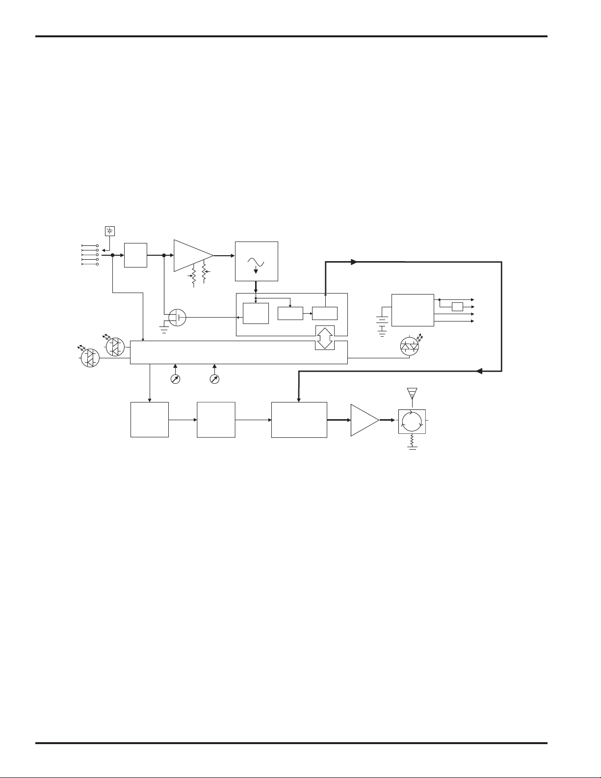
The 700 series encrypted digital wireless microphones use an all-digital communications link for excellent sound
quality and data security.
In the transmitter, the audio first passes through a DSP-controlled dual envelope analog limiter. The signal is then
digitized and fed to a DSP (digital signal processor). The DSP uses a proprietary audio encoding scheme to lower
the bit rate and provide the high entropy required for secure encryption. The bit stream is then encrypted, apportioned into packets, and sent over the air using a proprietary digital modulation scheme.
In the receiver, the digital baseband signal is demodulated to recover the original bit clock and data stream. The
DSP separates out the packet headers and decrypts the audio data. The audio data is then decoded to recover the
original audio signal.
Mic
Jack
1
2
3
4
5
+3.3V Bias
Supply
Encryption
Key Link
Bicolor
Modulation
LEDs
<--See 5-Pin Input Jack Wiring for details.
Hi/Lo
Pass
Filter
Phase
Locked
Loop
Input
Amp
LF
Rolloff
Shunt
Limiter
Freq
Switches
Audio
Audio
Level
Microprocessor
Voltage
Controlled
Oscillator
A-D
Converter
11001001
Dual
Envelope
Limiter
Digital Signal Processor
Encode
Digital
Modulator
Encrypt
Battery
RF
Amp
9V
Switching
Power
Supply
Isolator
50
Bicolor
Power
LED
+3.3v
+1.8v
+9v
-3v
DSP-CONTROLLED DUAL ENVELOPE ANALOG LIMITER
In order to make the very best use of the high quality A/D converter, microphone audio is limited in the analog
domain first before being sampled. The DSP controls this process, but because the limiting is done in analog, levels
near the converter’s maximum may be used without fear of clipping.
The limiter has a fast attack, but different release characteristics, depending on the nature of the signal that drove
the input into limiting. Brief transients result in a fast decay, to avoid “pumping” effects, while sustained loud signals
result in a slower decay, to keep distortion to a minimum. The result is a transparent-sounding limiter with excellent
low distortion characteristics.
DIGITAL SIGNAL PROCESSING AND MODULATION
The preamplified and limited audio signal is converted to digital using a 24-bit A/D converter and fed to the DSP.
Within the DSP, the audio is encoded to reduce the bit rate and increase entropy in the data stream prior to encryption. The data stream is then encrypted and apportioned into packets, delimited by packet headers. The complete
bit stream is modulated onto the carrier using a modified pi/4 DQPSK (differential quadrature phase shift keying)
method. This modulation method makes efficient use of the RF spectrum and is easy to demodulate reliably.
RF OUTPUT SECTION
Intermodulation (IM) occurs in the final amplifier stages of conventional transmitters when the transmitters are within
a few feet of each other. This can create serious problems in multichannel wireless systems when an IM signal falls
on the carriers, IF frequencies, local oscillator and image frequencies of the systems being operated. To eliminate
this problem in the UM700, the modulated radio signal passes through a circular isolator before entering the an-
4
LECTROSONICS, INC.
Page 5

Digital Frequency Agile UHF Belt-Pack Transmitter
tenna. The circular isolator functions like a “one-way check valve” to allow the RF signal to pass through to the
antenna, but not to pass backwards into the amplifier stage. RF signals from other nearby transmitters cannot reach
the output amplifier in the UM700. This provides excellent stability and eliminates IM in the output stage of the
transmitter.
LONG BATTERY LIFE
High efficiency circuits and switching power supplies throughout the design allow over 4.5 hours of operation using a
single 9 Volt alkaline battery. (A 9V lithium battery will provide over 14 hours of operation.) The battery compartment
is a unique mechanical design which automatically adjusts to fit any brand of battery. The battery contacts are spring
loaded to prevent “rattle” as the unit is handled.
FREQUENCY AGILITY
700 Series wireless systems are available on eight different “blocks” of 256 frequencies, from 537.600 to 767.900
MHz. Each of these blocks provides 256 selectable frequencies in 100 kHz steps over a 25.6 MHz bandwidth. This
wide variety of selectable frequencies alleviates carrier interference problems in mobile or traveling applications. Two
16-position rotary switches on the side panel of the unit are used to select the frequency.
The UM700 transmitter section uses a synthesized, frequency selectable main oscillator The frequency is extremely
stable over a wide temperature range and over time.
ANTENNA
At UHF frequencies, where wavelengths and antennas are shorter than at VHF frequencies, a resonant length wire
is preferred over using the microphone cable as the antenna. The antenna on the UM700 consists of a flexible 1/4
wavelength bronze cable, detachable via an SMA connector. The impedance of this connector is 50 Ohms.
ENCRYPTION SYSTEM
The 700 Series employs state-of-the-art 128-bit encryption for exceptional data security. (128-bit encryption means
there are 300 trillion, trillion, *trillion* possible keys, assigned with equal probability.) The system offers three levels
of security, trading off ease of use for immunity to attack.
LEVEL 1 offers the most intuitive operation. Once the key has been set, the equipment may be operated exactly the
same as a traditional analog system. The transmitter and receiver may be powered on in any sequence, and the
transmitter may move in and out of range without consequence (except normal squelching). Security in this mode is
excellent, but the scrambling sequence repeats approximately every 20,000 bits, theoretically exposing the user to
differential attacks. Due to its ease of use and quite effective security, level 1 is the default security level.
LEVEL 2 offers much greater encryption strength, at the cost of slightly less intuitive operation. In level 2, the
scrambling sequence never repeats (i.e. the PRNG is free-running), so the receiver must be on and ready to receive
when the transmitter is first switched on. Some signal loss is tolerated but if the transmitter should wander out of
range for more than ten seconds, it will be necessary to switch it off and on again to restart the sequence,
resynchronizing with the receiver. Security in this mode is a great deal stronger than level 1, since the scrambling
sequence never repeats. Only if the sequence is deliberately reused (i.e. by cycling transmitter power after prolonged
signal loss, or by reusing the same key session after session) is a differential attack possible even in theory.
LEVEL 3 offers the strongest encryption of all, again at the cost of some convenience. Level 3 is much like level 2,
except that the equipment itself enforces a policy that NO PORTION OF ANY SCRAMBLING SEQUENCE SHALL
EVER BE USED MORE THAN ONCE. This is a fundamental tenet of cryptography: key reuse leads to vulnerability.
Thus, level 3 security is about as close to the holy grail of the one-time pad as any wireless vendor is likely to offer at
a reasonable price. Operation is a little different in level 3:
• The transmitter starts sending immediately after receiving a key ONLY. It does not send when first powered on.
• Only one transmitter may receive each key.
• If the transmitter is out of range of the receiver for more than ten seconds, it will be necessary to generate a
new key in order to continue using the system.
All three levels offer strong encryption, so each user may make a policy decision based on an assessment of risk.
Those requiring ease of use may relax, knowing that eavesdropping is extremely difficult even in level 1. Many users
may find level 2 to be just as convenient, allowing them to use greater encryption strength. Those users willing to
follow stricter security procedures can use level 3, the strongest encryption available today from a wireless microphone.
Rio Rancho, NM – USA
5
Page 6

UM700
LECTROSONICS
UM700
ON
OFF
AUDIO
LEVEL
–10
CONTROLS AND FUNCTIONS
FREQUENCY
1.6MHz
0
F
E
D
C
B
A
9
0
1
1
F
2
6
7
8
2
E
3
3
D
C
4
4
5
B
5
6
A
9
7
8
100kHz
–20
ANTENNA
75 Hz
35
150
LF ROLL OFF
FCCID:DBZUM700
Lectrosonics, Inc.
Made in U.S.A.
SN:
XXXX
INPUT JACK
The input jack on the UM700 is a Switchcraft TA5M connector that accommodates virtually every lavaliere, hand-held
or shotgun microphone available, with positive or negative bias. The input will also cleanly handle line level signals
up to 300 mV before limiting. Use a Switchcraft TA5F connector on the microphone cable or input adapter cord .
See the separate sheet titled “Transmitter 5-Pin Input Jack Wiring” regarding the correct connections for
various microphones, and other sources.
ON/OFF SWITCH
Turns the battery power on and off. Even when the switch is turned off or on abruptly, the digital muting prevents
“thumps” or transients from occurring.
“ON” LAMP
Glows green when the battery is good and the ON/OFF switch is ON. The lamp will glow yellow/orange as the
battery voltage drops and finally glows red when there are about 30 minutes of operation left (with an alkaline
battery). The lamp will flash red when there are only a few minutes of life left. A NiMh battery will give little or no
warning when it is depleted. If you wish to use NiMh batteries in the UM400, we recommend trying fully charged
batteries in the unit, noting the length of time that the batteries will run the unit and in the future use somewhat less
than that time to determine when the battery needs to be replaced. A weak battery will sometimes light the POWER
LED to the “good” green indication immediately after being put in the unit, but will soon discharge to the point where
the LED will go red or shut down, just like a flashlight with “dead” batteries. If the lamp fails to light, the battery
should be replaced.
FREQUENCY ADJUST (located under the sliding door)
These two rotary switches adjust the center frequency of the carrier. The 1.6M
is a coarse adjustment and the 100K is the fine adjustment. Each transmitter is
factory aligned at the center of its operating range. The default position of the
frequency select switches is in the center of the transmitter’s range.
AUDIO LEVEL CONTROL
Used to adjust the audio input level for proper modulation.
6
LECTROSONICS, INC.
0
1
F
E
D
C
B
A
2
3
4
5
6
9
7
8
0
1
F
E
D
C
B
A
2
3
4
5
6
9
7
8
Page 7

Digital Frequency Agile UHF Belt-Pack Transmitter
MODULATION LEDS
Indicate the proper setting of the MIC LEVEL control. There are two bicolor modulation LEDs that can light either red
or green.
“-20dB level” One modulation LED glows green and the transmitter is 20 dB below full modulation.
“-10 dB level” Both modulation LEDs glow green and the transmitter is close to full modulation.
“+0 dB level” The -20 LED glows red and the -10 LED glows green. The transmitter is in slight limiting and is
fully modulated. This is probably desirable. See the discussion below under Input Limiter.
“+10 dB level” Both LEDs are red. The transmitter is in limiting and you may want to reduce the transmitter audio
gain. See the discussion below under Input Limiter.
When the transmitter is first switched on, the modulation LEDs blink a code that indicates the current security level: 1
blink = level 1, 2 blinks = level 2 and 3 blinks = level 3.
Input Limiter
The 700 series transmitters employ a digitally-controlled analog audio limiter just before the analog-to-digital converter. The limiter has a range of more than 30dB for excellent overload protection. A dual release envelope makes
the limiter acoustically transparent while maintaining low distortion. It can be thought of as two limiters in series,
connected as a fast attack and release limiter followed by a slow attack and release limiter. The limiter recovers
quickly from brief transients, so that its action is hidden from the listener, but recovers slowly from sustained high
levels, to both keep audio distortion low and preserve short term dynamic changes.
The audio level LEDs indicate limiter activity. The first red LED indicates that the limiter is active and that the transmitter is fully modulated (audio level is between +0 and +10 dB). The second red LED indicates that the level is
10dB or more into limiting. Occasional forays into the red are desirable for most applications, since the distortion
introduced by the limiter is so minimal, and full modulation is thus assured. We strongly recommend setting the gain
of the transmitter high enough so that the first red LED occasionally lights.
Generally speaking, some limiting is desirable in normal operation to improve the signal to noise ratio of the system.
The limiting action is not audible and does not create distortion. A highly trained ear would hear only the compression of the peaks in the audio signal, which is desirable with most recorders and many sound reinforcement systems.
ANTENNA
The flexible bronze cable antenna supplied with the transmitter is cut to 1/4 wavelength of the center of the frequency
block (the frequency range) of the transmitter. It is removable via an SMA connector. The SMA connector is a 50
Ohm RF port which can also be connected directly to test equipment. Replacement antennas are available in precut lengths for specific frequency blocks, or as a kit with instructions to cut the antenna for any frequency block.
Replacement antenna is part AMM(xx) where “xx” indicates the frequency block, ie. AMM27 for block 27.
ADJUSTABLE LOW FREQUENCY ROLL-OFF
A 18dB per octave low frequency roll-off is provided in the audio section, with the -3dB point adjustable from 35Hz to
150Hz. The actual roll-off frequency will vary somewhat according to the low frequency response of the mic capsule
being used.
The low frequency roll-off control is used to reduce the undesirable effects of very low frequency audio often produced by air conditioning systems, automobile traffic and other sources. Excessive low frequency content in the
audio input can cause overload of the program audio in recording applications. In sound reinforcement systems,
excessive low frequency content can cause excessive power amplifier drain or even damage to loudspeaker systems. A common example is wind blowing across a microphone, causing very high levels of low frequency audio
(“wind noise”). By rotating the roll-off control clockwise, the hinge point of the roll-off is increased to reduce the level
of low frequencies. In low noise situations, such as a motion picture production set indoors where environmental
noise is minimal, the control can be rotated counterclockwise to permit low frequency audio to be captured.
THE BELT CLIP
The belt clip may be removed for special applications by removing one screw.
USE ONLY THE SCREW THAT IS SUPPLIED
The circuitry is tightly packed into this unit. A longer screw will permanently damage the transmitter! Use only
Lectrosonics PN:28528 which is a Phillips head, 4-40 x 3/16", FL100 screw.
Rio Rancho, NM – USA
7
Page 8

UM700
BATTERY INSTALLATION
The transmitter is powered by a standard alkaline or lithium 9 Volt battery. It is important that you use ONLY an
ALKALINE or LITHIUM battery for longest life. Standard zinc-carbon batteries marked “heavy-duty” or “long-
lasting” are not adequate. Ni-cad rechargeable batteries will only provide 1.5 hours of operation, or less, and will
run down quite abruptly. Unless it is cold, alkaline batteries provide over 4.5 hours of operation. Lithium batteries
can be used to provide up to 14 hours. Care should be taken not to leave a fully discharged lithium battery in the
transmitter, as swelling of the battery can make it difficult to remove from the compartment. The battery status
circuitry is designed for the voltage drop over the life of alkaline batteries.
To open the battery compartment, press outward on the cover door in the direction of the arrow as shown in the
drawing. Only firm, sliding pressure is needed to open and close the battery door. Swing the door open and take
note of the polarity marked inside showing the location of the positive (+) and negative (-) terminals. You can see the
large and small contact holes inside the battery compartment with the door open.
Swing the
Press outward on the
battery door in this
direction.
door open
Insert the battery correctly and close the cover by pressing the door closed and across, reversing the opening
procedure illustrated above. If the battery is inserted incorrectly, the door will not close. Do not force the door
closed.
8
LECTROSONICS, INC.
Page 9

Digital Frequency Agile UHF Belt-Pack Transmitter
OPERATING INSTRUCTIONS
1) Install a fresh battery according to the instructions above.
2) Insert the microphone plug into the input jack, aligning the pins; be sure that the connector locks in.
3) Attach the antenna to the SMA connector on the top of the transmitter.
4) Mute the sound system.
5) Turn the transmitter power switch to the “ON” position.
Note: If the security level is set to “2”, the receiver must be powered on before the transmitter.
If the security level is set to “3”, communications do not begin until a fresh key is transfered.
6) Position the microphone in the location you will use in actual operation.
7) While speaking or singing at the same voice level that will actually be used, observe the MODULATION LEDs.
Adjust the AUDIO LEVEL control knob until the LEDs begin to light. At too low a setting neither LED will light as
you speak. Gradually, turn the gain up until the –20 dB LED lights green and then the -10 dB lights green. We
strongly recommend setting the gain of the transmitter even higher so that the first red LED occasionally lights.
8) Once the gain has been adjusted, the audio system audio can be turned on to make level adjustments in the
main audio system.
OPERATING NOTES
The AUDIO LEVEL control knob should not be used to control the volume of your sound system or recorder levels.
This gain adjustment matches the transmitter gain with the user’s voice level and microphone positioning.
If the audio level is too high — both red LEDs will light frequently or stay lit. This condition may reduce the dynamic
range of the audio signal.
If the audio level is too low — neither LED will light, or only the -20 LED will light green. This condition may cause
hiss and noise in the audio.
Different voices will usually require different settings of the AUDIO LEVEL control, so check this adjustment as each
new person uses the system. If several different people will be using the transmitter and there is not time to make
the adjustment for each individual, adjust it for the loudest voice.
ADJUSTING THE TRANSMITTER FREQUENCY
If you are experiencing interference from another signal on your frequency, you
may want to change the operating frequency of your system. The left switch
changes the operating frequency by 1.6 MHz per step and the right switch
changes it 100 kHz per step. If you are experiencing interference, change the
operating frequency in 100 kHz steps to find a clear channel. If it is not possible
to find a clear channel using the 100 kHz switch, return it to its original position
and change the 1.6 MHz switch by one click then try the 100 kHz switch again.
To gain access to these switches, slide the access door sideways with a fingernail.
The UDR700 receiver front panel will indicate the correct switch settings to match the receiver frequency.
0
1
F
E
D
C
B
A
2
3
4
5
6
9
7
8
0
1
F
E
D
C
B
A
2
3
5
6
9
7
8
4
Rio Rancho, NM – USA
9
Page 10
UM700
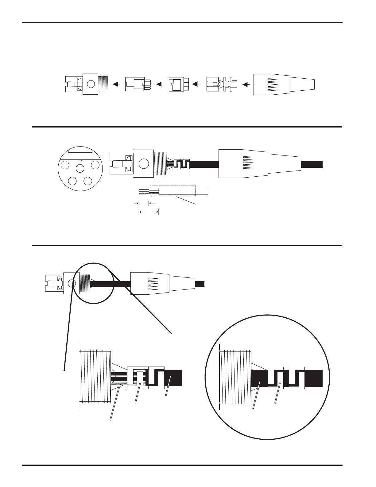
MICROPHONE CORD TERMINATION
TA5F Connector Assembly
1
2 3
VIEW FROM SOLDER
SIDE OF PINS
4
5
This is the correct way.
0.15"
0.3"
Heatshrink
Tubing
Mic Cord Stripping Instructions
Be sure the shield wire touches the metal crimp
tab. This helps prevent any AM component of the
transmitter signal from entering the mic and
causing a "whine."
Note that this is opposite from our VHF
transmitter wiring where the shield should not
touch any metal part of the housing.
Don't do it this way!
10
Shield Wire
Crimp
Tabs
Rubber
Insulation
LECTROSONICS, INC.
Rubber
Insulation
Crimp
Tabs
Page 11

Digital Frequency Agile UHF Belt-Pack Transmitter
s
5-PIN INPUT JACK WIRING
The wiring diagrams shown on the next page represent the basic wiring necessary for the most common types of
microphones and other audio inputs. Some microphones may require extra jumpers or a slight variation on the
diagrams shown.
It’s virtually impossible to keep completely up to date on changes that other manufacturers make to their products. It
is possible that you may encounter a microphone that differs from these instructions. If this occurs please call our
toll-free number listed in the back manual. Our service department can answer your questions regarding microphone compatibility.
When used on a wireless transmitter, the microphone element is in the proximity of the RF coming from the transmitter. The nature of electret microphones makes them sensitive to RF, which can cause problems with the microphone/
transmitter compatibility. If the electret microphone is not designed properly for use with wireless transmitters, it may
be necessary to install a chip capacitor in the mic capsule or connector to block the RF from entering the electret
capsule. This modification is shown on the next page.
LECTROSONICS
4
3
5
2
1
1
2
3
4
5
NEG GND (OR BIAS)
POS BIAS (OR GND)
MIC
SOURCE LOAD
LINE IN
FB
330pF
100
330pF
4k
330pF
40k
330pF
+
+
10uF
1k
3.2V Mic Bia
To Mic Amp
Input Jack Input Circuit
PIN 1 Shield (ground) for positive biased electret lavaliere microphones. For the increasingly rare negative biased
electret lavaliere microphones, it is the bias voltage source. It is also the shield (ground) for dynamic microphones and line level inputs.
PIN 2 Shield (ground) for negative biased electret lavaliere microphones. Bias voltage source for positive biased
electret lavaliere microphones.
PIN 3 Low impedance microphone level input for dynamic microphones. Also accepts hand-held electret micro-
phones that have their own battery or power supply.
PIN 4 4K Ohm source load for non-Lectrosonics electret microphones. Use in conjunction with other pins to
provide attenuation of high level input signals.
PIN 5 40k high impedance, line level input for tape decks, mixer outputs, musical instruments, etc.
Rio Rancho, NM – USA
11
Page 12
UM700
R
3
RF BYPASSING
2 WIRE MIC 3 WIRE MIC
Some mics require RF protection to keep the radio signal
from affecting the capsule, even though the transmitter
input circuitry is already RF bypassed (see schematic
diagram).
If the mic is wired as directed, and you are having
difficulty with squealing, high noise, or poor frequency
response; RF is likely to be the cause.
The best RF protection is accomplished by installing RF
Preferred locations for bypass capacitors
SHIELD
AUDIO
CAPSULE
TA5F
CONNECTOR
Alternate locations for bypass capacitors
CAPSULE
SHIELD
AUDIO
BIAS
TA5F
CONNECTO
bypass capacitors at the mic capsule. If this is not
possible, or if you are still having problems, capacitors
can be installed on the mic wires inside the TA5F connector housing.
Install the capacitors as follows: Use 330 pF capacitors. Capacitors are available from Lectrosonics. Please specify
the part number for the desired lead style.
Leaded capacitors: P/N 15117 Leadless capacitors: P/N SCC330P
The Lectrosonics M150-700 lavalier mic is bypassed correctly for use with the UM700 and is the recommended
microphone for the 700 Series wireless system.
LINE LEVEL SIGNALS
The normal hookup for line level signals is: Signal Hot to pin 5, Signal Gnd to pin 1, pin 4 jumped to pin 1, and pin
3 jumped to pin 1. This gives a 40dB attenuator that allows signal levels much higher than 3V to be applied without
limiting.
If more headroom is needed, insert a 100k resistor in series with pin 5. Put this resistor inside the TA5F connector to
minimize noise pickup.
If lower than normal line levels (less than 1V) are expected, use this hookup: Signal Hot to pin 5, Signal Gnd to pin
1, and pin 4 jumpered to pin 1. This provides a 20dB attenuator allowing signals as high as 3V to be applied without
limiting.
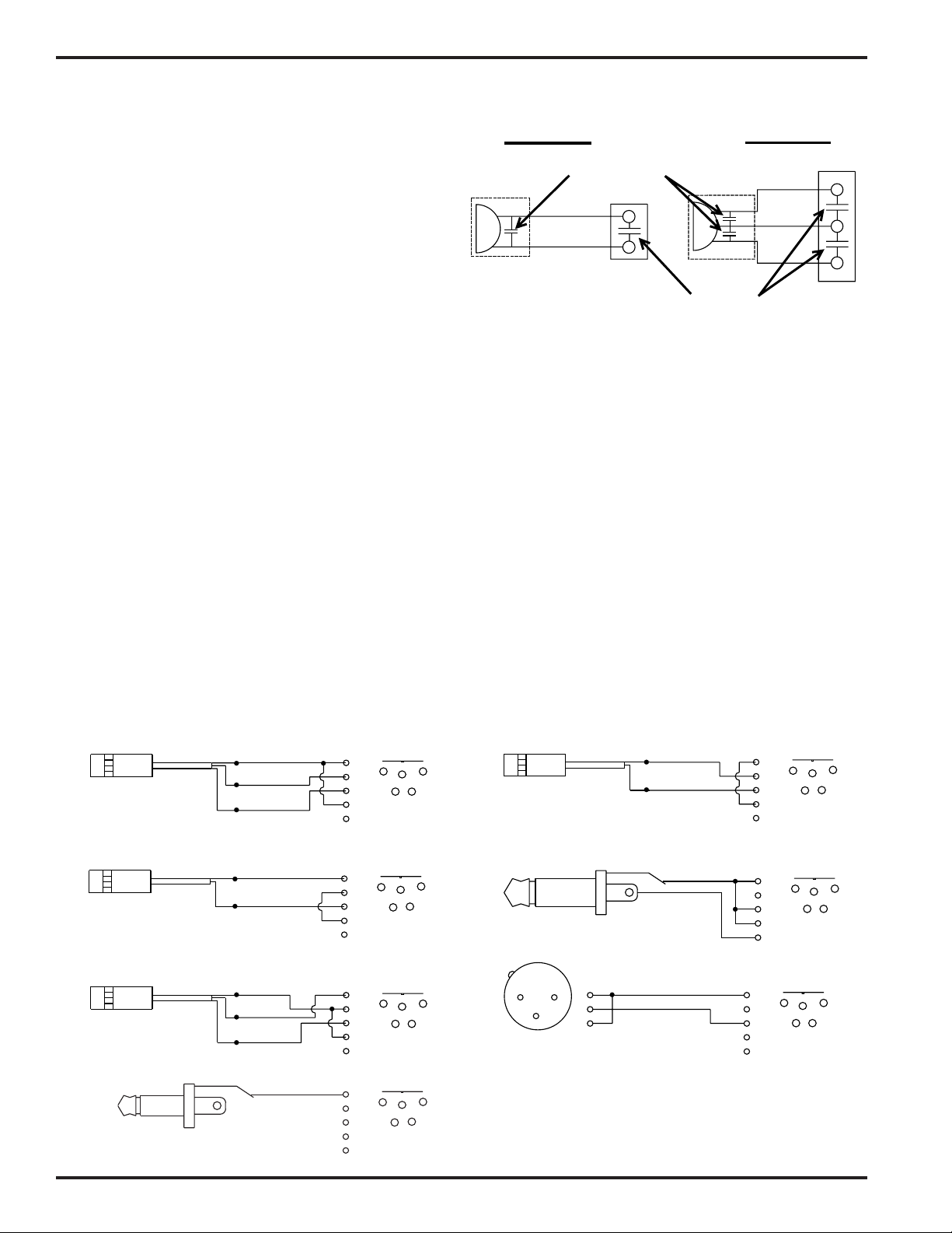
WIRING HOOKUPS FOR DIFFERENT SOURCES
PIN
PIN
PIN
1
2
3
4
5
1
2
3
4
5
1
2
4
3
4
5
4
3
PLUG
4
3
3
TA5F
PLUG
5
TA5F
5
TA5F
PLUG
5
1
2
1
2
1
2
3 WIRE ELECTRET MIC
POSITIVE BIAS
2 WIRE ELECTRET MIC
POSITIVE BIAS
WIRE ELECTRET MIC
NEGATIVE BIAS
SLEEVE
Mini Plug
SHIELD
BIAS
AUDIO
SHIELD
AUDIO
SHIELD
BIAS
AUDIO
SHIELD
DATA
TIP
Encryption Cable
PIN
PIN
PIN
PIN
1
2
3
4
5
1
2
3
4
5
1
2
3
4
5
1
2
3
4
5
4
3
TA5F
PLUG
4
3
TA5F
PLUG
4
3
TA5F
PLUG
4
3
TA5F
PLUG
1
5
2
2 WIRE ELECTRET MIC
NEGATIVE BIAS
SLEEVE
1
5
2
TIP
LINE LEVEL
RCA or 1/4 " PLUG
(See notes on ‘LINE LEVEL SIGNALS” above.)
PIN
1
2
1
5
2
DYNAMIC
MIC LEVEL
1
5
2
1
2
3
3
Dynamic LO Z mic or electret with
manufacturers power supply.
SHIELD
AUDIO
SHIELD
AUDIO
SHIELD
12
LECTROSONICS, INC.
Page 13

Digital Frequency Agile UHF Belt-Pack Transmitter
TROUBLESHOOTING
Before going through the following chart, be sure that you have a good battery in the transmitter. It is important that
you follow these steps in the sequence listed.
SYMPTOM POSSIBLE CAUSE
TRANSMITTER BATTERY LED OFF 1) Battery is inserted backwards.
2) Battery is dead.
NO TRANSMITTER MODULATION LEDs 1) Gain control turned all the way down.
2) Battery is in backwards. Check power LED.
3) Mic capsule is damaged or malfunctioning.
4) Mic cable damaged or mis-wired.
RECEIVER RF LAMP OFF 1) Transmitter not turned on.
2) Transmitter battery is dead.
3) Receiver antenna missing or improperly positioned.
4) Transmitter and receiver not on same frequency. Check
switches/display on transmitter and receiver.
5) Operating range is too great.
6) Transmitter antenna not connected
NO SOUND (OR LOW SOUND LEVEL),
RECEIVER MOD LEVEL LEDs ARE ON
DISTORTED SOUND 1) Transmitter gain (audio level) is far too high. Check mod
HISS AND NOISE -- AUDIBLE DROPOUTS 1) Transmitter gain (audio level) far too low.
EXCESSIVE FEEDBACK 1) Transmitter gain (audio level) too high. Check gain
1) Receiver output level set too low.
2) Receiver output is disconnected; cable is defective
or mis-wired.
3) Sound system or recorder input is turned down.
level lamps on transmitter and receiver as it is being used.
(refer to pages 8/9 for details on gain adjustment)
2) Receiver output may be mismatched with the sound
system or recorder input. Adjust output level on receiver
to the correct level for the recorder, mixer or sound
system.
3) Excessive wind noise or breath “pops.” Reposition
microphone and/or use a larger windscreen.
4) Transmitter is not set to same frequency as receiver.
Check that frequency select switches on receiver and
transmitter match.
2) Receiver antenna missing or obstructed.
3) Transmitter antenna missing.
4) Operating range too great.
adjustment and/or reduce receiver output level.
2) Transmitter too close to speaker system.
3) Mic is too far from user’s mouth.
MICROPHONE HAS A “WHINE” NOISE IN THE
BACKGROUND WHICH VARIES AS THE MIC CABLE
IS MOVED
RECEIVER OUTPUTS AN EXTREMELY LOUD,
HISSY, SWISHY SOUND
NO AUDIO OUTPUT, AUDIO LEDS BLINK IN
SEQUENCE, LED DISPLAY SHOWS
“POWER TX OFF+ON” OR “NEW KEY REQUIRED”
1) Install bypass capacitors at both ends of the mic cable or
use the factory supplied microphone.
1) Encryption keys in transmitter and receiver do not match.
Refer to receiver manual to choose a new key and send it
to the transmitter.
1) System is in security level 3 and is not synchronized.
to correct this in security level 2, turn the transmitter off
then on again. In level 3, a new key must be generated.
SECURITY FEATURES DIFFERENT FROM 1) This manual applies only to UDR700 version 3.0/3.0 and
THE DOCUMENTATION higher.
Rio Rancho, NM – USA
13
Page 14

UM700
SPECIFICATIONS AND FEATURES
Operating principle: Proprietary digital modulation with encryption
Modulation type: Modified pi/4 DQPSK
Sample rate: 44.1 ksps
Audio coder: Proprietary sub-band ADPCM
Encryption key length: 128 bit (300 trillion trillion trillion keys)
Bit rate: 220,500 bps including packet overhead
Operating frequencies: 537.600 to 793.500 MHz depending upon local regulations
Frequency selection: 256 frequencies in 100kHz steps
RF Power output: 50 mW (nominal)
Frequency stability: ± 0.001%
Equivalent input noise: –119 dBV, A-Weighted
Spurious radiation: 70 dB below carrier
Input Level: Nominal 2 mV to 300 mV before limiting
Greater than 1V maximum with limiting
Input impedance: Taps provided for 100, 4k, 40k Ohm
Input compressor: Dual-envelope limiter; 30 dB range
Gain control range: 43 dB; semi-log rotary control
Modulation indicators: Dual multi-color LEDs indicate modulation level in 4 steps at
-20, -10, 0, +10 dB with green and red indications
Low frequency roll-off
adjustment: –18dB/octave; 35Hz to 150Hz
Controls: 2 position “ON-OFF” slide switch. Front panel knob adjusts audio gain.
Recessed control on side panel adjusts low frequency rolloff. Rotary
switches on side panel adjust transmitter frequency.
Audio Input Jack: Switchcraft 5 pin locking (TA5M)
Antenna: Detachable, flexible 1/4 wave bronze cable. 50 Ohm port allows
connection to test equipment.
Battery: Precision compartment auto-adjusts to accept any known alkaline 9 Volt
battery. (We’ve tried 246 different ones!)
Battery Life: 5 hours (alkaline); 16 hours (lithium)
Weight: 6.3 ozs. including battery
Dimensions: 3.1 x 2.4 x .75 inches
Emission Designator: 180KQ2E
System Specifications
Audio frequency response: 40Hz to 20kHz, +/- 1dB
Audio dynamic range: >100 dB before limiting
Audio Distortion: 0.05% THD + noise at 1kHz
14
Specifications subject to change without notice.
LECTROSONICS, INC.
Page 15

Digital Frequency Agile UHF Belt-Pack Transmitter
SERVICE AND REPAIR
If your system malfunctions, you should attempt to correct or isolate the trouble before concluding that the equipment
needs repair. Make sure you have followed the setup procedure and operating instructions. Check out the interconnecting cords and then go through the TROUBLE SHOOTING section in the manual
We strongly recommend that you do not try to repair the equipment yourself and do not have the local repair shop
attempt anything other than the simplest repair. If the repair is more complicated than a broken wire or loose connection, send the unit to the factory for repair and service. Don’t attempt to adjust any controls inside the units.
Once set at the factory, the various controls and trimmers do not drift with age or vibration and never require readjustment. There are no adjustments inside that will make a malfunctioning unit start working.
LECTROSONICS service department is equipped and staffed to quickly repair your equipment. In-warranty repairs
are made at no charge in accordance with the terms of the warranty. Out of warranty repairs are charged at a
modest flat rate plus parts and shipping. Since it takes almost as much time and effort to determine what is wrong
as it does to make the repair, there is a charge for an exact quotation. We will be happy to quote approximate
charges by phone for out of warranty repairs.
RETURNING UNITS FOR REPAIR
You will save yourself time and trouble if you will follow the steps below:
A. DO NOT return equipment to the factory for repair without first contacting us by letter or by phone. We need to
know the nature of the problem, the model number and the serial number of the equipment. We also need a phone
number where you can be reached 8 am to 4 pm (Mountain Standard Time).
B. After receiving your request, we will issue you a return authorization number (R.A.). This number will help speed
your repair through our receiving and repair departments. The return authorization number must be clearly shown
on the outside of the shipping container.
C. Pack the equipment carefully and ship to us, shipping costs prepaid. If necessary, we can provide you with the
proper packing materials. UPS is usually the best way to ship the units. Heavy units should be “double-boxed” for
safe transport.
D. We also strongly recommend that you insure the equipment, since we cannot be responsible for loss of or damage
to equipment that you ship. Of course, we insure the equipment when we ship it back to you.
Mailing address: Shipping address: Telephones:
Lectrosonics, Inc. Lectrosonics, Inc. Regular: (505) 892-4501
PO Box 15900 581 Laser Rd. Toll Free (800) 821-1121
Rio Rancho, NM 87174 Rio Rancho, NM 87124 FAX: (505) 892-6243
USA USA
World Wide Web: http://www.lectrosonics.com Email: sales@lectrosonics.com
Rio Rancho, NM – USA
15
Page 16

LIMITED ONE YEAR WARRANTY
LIMITED ONE YEAR WARRANTY
The equipment is warranted for one year from date of purchase against defects in
materials or workmanship provided it was purchased from an authorized dealer. This
warranty does not cover equipment which has been abused or damaged by careless
handling or shipping. This warranty does not apply to used or demonstrator equipment.
Should any defect develop, Lectrosonics, Inc. will, at our option, repair or replace any
defective parts without charge for either parts or labor. If Lectrosonics, Inc. cannot
correct the defect in your equipment, it will be replaced at no charge with a similar new
item. Lectrosonics, Inc. will pay for the cost of returning your equipment to you.
This warranty applies only to items returned to Lectrosonics, Inc. or an authorized
dealer, shipping costs prepaid, within one year from the date of purchase.
This Limited Warranty is governed by the laws of the State of New Mexico. It states the
entire liablility of Lectrosonics Inc. and the entire remedy of the purchaser for any
breach of warranty as outlined above. NEITHER LECTROSONICS, INC. NOR
ANYONE INVOLVED IN THE PRODUCTION OR DELIVERY OF THE EQUIPMENT
SHALL BE LIABLE FOR ANY INDIRECT, SPECIAL, PUNITIVE, CONSEQUENTIAL,
OR INCIDENTAL DAMAGES ARISING OUT OF THE USE OR INABILITY TO USE
THIS EQUIPMENT EVEN IF LECTROSONICS, INC. HAS BEEN ADVISED OF THE
POSSIBILITY OF SUCH DAMAGES. IN NO EVENT SHALL THE LIABILITY OF
LECTROSONICS, INC. EXCEED THE PURCHASE PRICE OF ANY DEFECTIVE
EQUIPMENT.
This warranty gives you specific legal rights. You may have additional legal rights which
vary from state to state.
LECTROSONICS, INC.
581 LASER ROAD
RIO RANCHO, NM 87124 USA
www.lectrosonics.com
May 20, 2003
 Loading...