

Page 1

UH200D
FREQUENCY-AGILE
PLUG-ON UHF TRANSMITTER
OPERATING INSTRUCTIONS
and trouble-shooting guide
LECTROSONICS, INC.
Rio Rancho, NM
www.lectrosonics.com
Page 2

INTRODUCTION
Thank you for selecting the Lectrosonics UH200D frequency agile, plug-on transmitter. The
UH200D combines over 80 years of engineering experience with the very latest components, in
a design that addresses the most demanding professional applications.
The design of the UH200D was the direct result of numerous conversations with users, staging
and touring companies and dealers across the US. The specific concerns and needs brought up
in these conversations led directly to the development of the operational features offered on the
UH200D. Two hundred fifty six frequencies are user selectable in 100kHz steps to alleviate
interference problems in travelling venues.
The UH200D is a rugged, machined aluminum package. Selectable voltage phantom power is
provided on pins 2 and 3. Level indicating LEDs are provided to make level settings quick and
accurate, without having to view the receiver. The battery compartment accepts any 9 Volt
alkaline or lithium battery and makes a positive connection via self-adjusting contacts.
Only the UH200D transmitter is covered in this manual. Companion receivers are covered in
separate manuals. The UH200D will operate with any 200 Series Lectrosonics receiver in the
same frequency group.
TABLE OF CONTENTS
INTRODUCTION ................................................................................................... 2
GENERAL TECHNICAL DESCRIPTION .............................................................. 3
CONTROLS AND FUNCTIONS ............................................................................ 4
OPERATING INSTRUCTIONS ............................................................................. 6
TROUBLESHOOTING .......................................................................................... 7
SPECIFICATIONS AND FEATURES.................................................................... 9
SERVICE AND REPAIR ...................................................................................... 10
RETURNING UNITS FOR REPAIR .................................................................... 10
WARRANTY .......................................................................................... Back cover
The UH200D transmitter is FCC type accepted under Part 74: 470 - 608MHz and 614 - 806MHz
2
Page 3
Frequency Agile Plug-on UHF Transmitter
GENERAL TECHNICAL DESCRIPTION
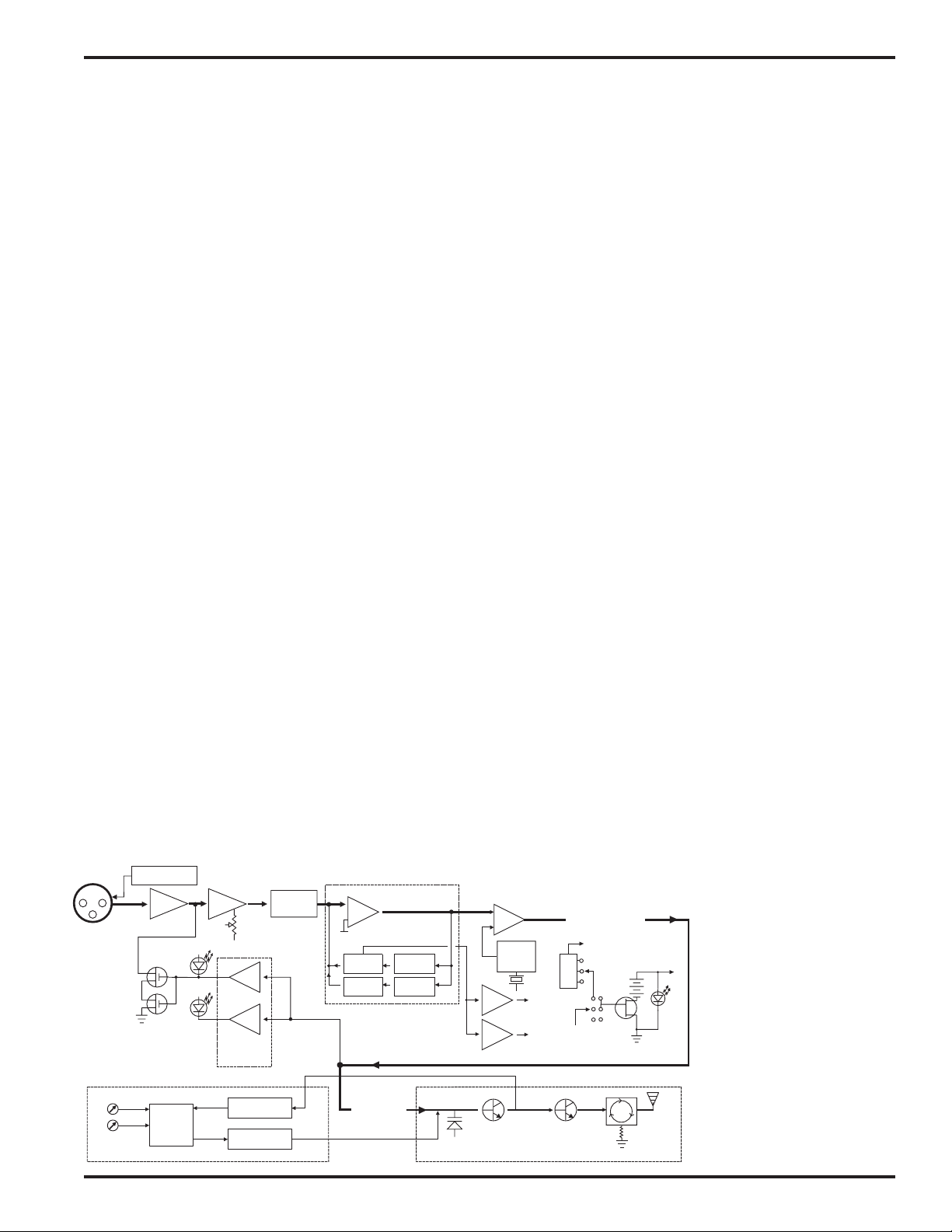
The UH200D transmitters are comprised of a number of functional subsystems as shown in the block diagram below.
GENERAL
The 200 system uses 75kHz wide deviation for an extremely high
signal to noise ratio. The transmitter circuits are all regulated to
allow full output power from the beginning (9 Volts) to the end
(6.5 Volts) of battery life. The input amplifier uses an ultra low
noise op amp. It is gain controlled with a wide range input
compressor which cleanly limits input signal peaks over 30dB
above full modulation.
DUAL BAND COMPANDOR
Traditionally, compandors have been a source of distortion in
wireless microphone systems. The basic problem with conventional systems is that the attack and decay times are always a
compromise. If the time constants are fast, high frequency
transients will not be distorted, but this will cause low frequency
distortion. If the time constants are slower, low frequency audio
distortion will be low, but high frequency transients will then be
distorted. The 200 system introduces an entirely new approach
to solving this basic problem, called “dual-band companding.”
There are actually two separate compandors in the 200 system,
one for high frequencies and one for low frequencies. A crossover network separates the frequency bands at 1kHz with a 6dB
per octave slope, followed by separate high and low frequency
compandors. The attack and release times in the high frequency
compandor are fast enough to keep high frequency transient
distortion at a low level, and the low frequency compandor uses
slower time constants, reducing low frequency distortion to well
below that of a conventional compandor.
NO PRE-EMPHASIS/DE-EMPHASIS
The signal to noise ratio of the 200 system is high enough to
preclude the need for conventional pre-emphasis (HF boost) in
the transmitter and de-emphasis (HF roll off) in the receiver. Preemphasis and de-emphasis in an FM radio system usually
provides about a 10dB improvement in the signal to noise ratio of
the system, but the high frequency boost in the transmitter must
be removed in a purely complementary manner or else the
frequency response of the original audio signal will be altered.
Pre-emphasis can also cause distortion in the receiver. As this
signal is passed through the IF filters in the receiver, distortion
INPUT
JACK
SHUNT
LIMITER
+5V / +15V / +48V
BIAS SUPPLY
BUFFER
LIMIT
LED
SET
LED
INPUT
AMP
PEAK AUDIO
INDICATOR &
LIMITER
DRIVER
AUDIO
LEVEL
LP
FILTER
Vref
COMPANDOR
BASS
TREBLE
LP FILTER
HP FILTER
can be produced, most noticeable at full modulation. De-emphasis cannot be applied until the signal is converted into audio, so
there is no way around this problem short of eliminating preemphasis altogether. Neither of these problems occur in the 200
system. The dual-band compandor in the 200 Series system
essentially provides a dynamic pre-emphasis/de-emphasis function with extremely low distortion.
PILOT TONE SQUELCH
The 200 system utilizes an ultrasonic tone modulation of the
carrier to operate the receiver squelch. This “pilot tone” consists
of a 32kHz signal mixed with the audio signal after the compandor,
to control the audio output muting of the receiver. The pilot tone
is filtered out of the audio signal immediately after the detector in
the receiver so that it does not influence the compandor or
various gain stages. The basic benefit of the pilot tone squelch
system is that the receiver will remain muted until it receives the
pilot tone from the matching transmitter, even if a strong RF
signal is present on the carrier frequency of the system. This is
extremely important in applications that include an automatic
microphone mixer.
WIDE-BAND DEVIATION
±75kHz deviation improves the capture ratio, signal to noise ratio
and AM rejection of a wireless system dramatically, compared to
the more commonly used ±15kHz deviation.
LONG BATTERY LIFE
High efficiency circuits throughout the design allow over 4.5
hours of operation using a single 9 Volt alkaline battery. (A 9V
lithium battery will provide over 12 hours of operation.) The
battery compartment is a unique mechanical design which automatically adjusts to fit any brand of battery. The battery contacts
are spring loaded to prevent “rattle” as the unit is handled. The
battery life will be affected by the amount of phantom power
supplied to any microphones that require it. A high drain 48 Volt
microphone can shorten battery life by 40% or more. A light drain
15 Volt microphone will make little or no difference in battery life.
The only way to be sure is to test the transmitter and microphone
combination with a brand new battery; then and only then will you
be sure of the combination's battery life.
FREQUENCY AGILITY
The transmitter section uses a synthesized, frequency selectable
main oscillator. The frequency is extremely stable over a wide
temperature range and over time.
Two rotary switches, located
on the side panel of the unit,
provide 256 frequencies in
100kHz steps over a 25.5MHz
range. This alleviates carrier
interference problems in mobile or travelling applications.
PWR
LED
Vreg
Vreg
PILOT
TONE
OSC
+5VDC
+3.6VDC
COMPANDED AUDIO
TO XMTR
TO INPUT JACK
5V
48V
15V
BIAS
POWER
+9VDC
PHASE LOCKED LOOP
DIVIDER
FREQ
SWITCHES
PRESCALER
LOW PASS
FILTER
COMPANDED
AUDIO
VOLTAGE
CONTROLLED
OSCILLATOR
TRANSMITTER
Rio Rancho, NM – USA
50
ISOLATOR
UH200D Block Diagram
3
Page 4
LIMIT LED
0
1
2
3
4
5
6
7
8
9
A
B
C
D
E
F
0
1
2
3
4
5
6
7
8
9
A
B
C
D
E
F
LEVEL LED
POWER
ON/OFF
LED
INPUT
JACK
MIC LEVEL
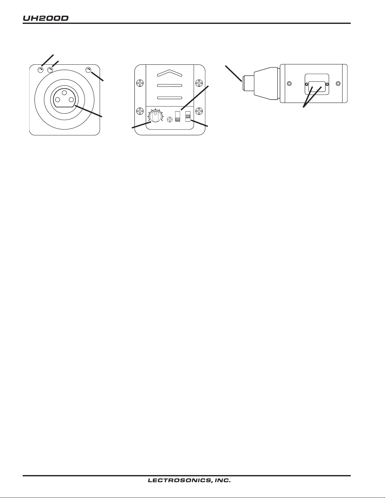
CONTROLS AND FUNCTIONS
INPUT
JACK
POWER
SWITCH
LEVEL
N O PHTM
P HTM
PWR OFF
5V
48 V
1 5V
PHANTOM POWER
VOLTAGE SELECT
FREQUENCY
1.6MHz 100kHz
FREQUENCY SWITCHES
(BEHIND DOOR)
Top View
Control Panel
The UH200D may be used with a wide variety of microphones.
The 3-pin XLR connector on the UH200D allows the transmitter
to be used with any dynamic microphone, as well as many two
wire positive bias lavaliere systems (such as those systems
supplied by Lectrosonics).
POWER SWITCH
Turns the battery power on and off. Even when the switch is
turned off or on abruptly, the pilot tone muting system prevents
“thumps” or transients from occurring.
The PHTM (center) position of the power switch turns on the
phantom power while the NO PHTM (fully on) position disables
phantom power. Be careful to use the center position phantom
power only when necessary and keep the voltage selector switch
in the 5 Volt position for additional protection against accidents.
PHANTOM POWER VOLTAGE SELECT SWITCH
This switch selects from three voltages when the PWR switch is
in the mid position. The voltages are:
• 5 Volts for lavaliere microphones,
• 15 Volts for some professional mics requiring high current and
for many common stage mics that will operate over a wide
phantom voltage range of 12 to 48 Volts. With the proper
adapter, this position can also be used with T power microphones. See our web site for details on finding or making the
proper adapter.
• 42 Volts for microphones that do in fact require a supply
greater than 15 Volts. (See below for a discussion of why 42
and not a “true” 48 Volts.)
For longest battery life use the minimum phantom voltage necessary for the microphone. Many stage microphones regulate the
48 Volts down to 10 Volts or so internally anyway, so you might
as well use the 15 Volt setting and save some battery power. If
you are not using a microphone for the input device, turn the
Side View
phantom power off (off is the fully up position of the power
switch). The phantom power should only be used with a fully
floating, balanced device such as almost any type microphone
with a 3 pin XLR connector. If you use the phantom power with an
unbalanced device or if pins 2 or 3 are DC connected to ground,
then you will draw maximum current from the power supply. The
UH200D is fully protected against such shorts but the 9 Volt
battery will be drained at twice its normal rate.
The transmitter can supply 4 mA at 42 Volts, 8 mA at 15 Volts,
and 8 mA at 5 Volts. The 42 Volts setting actually supplies the
same voltage to a 48 Volt microphone as the DIN standard
arrangement due to a dynamic biasing scheme that does not
have as much voltage drop as the DIN standard. The 48 Volt DIN
standard arrangement protects against shorts and high fault
current with high resistance in the power supply feeds to pins 2
and 3. This protects the supply if the supply current is accidentally shorted to ground and also keeps the microphone from
being attenuated by the power supply. The UH200D improves on
those functions and is able to use less power from the battery by
using constant current sources and current limiters. With this
dynamic arrangement the UH200D can also supply more than
twice the current of competing 48 Volt plug on units and provide
4 times the current to some very high end 15 Volt microphones.
The 5 Volt setting is provided for lavaliere microphones made by
us and others. Do not power lavalieres from the 15 or 48 Volt
setting as the microphone will be most likely destroyed.
Lectrosonics makes an adapter, MCA5X, that will adapt our
standard TA5F 5 pin microphones to the UH200D. This adapter
also provides protection against excessive phantom voltage. If
voltages higher than 5 Volts are applied to the adapter, a Zener
will shunt excess voltage to ground. The microphone won't work
until the voltage is correctly reduced to 5 Volts. If you have an
older lavaliere mic that was wired directly to an XLR for use with
the earlier UH200's, we strongly recommend building our protection circuit into the XLR to prevent accidental destruction of the
lavaliere.
4
Page 5

Frequency Agile Plug-on UHF Transmitter
INPUT JACK
Standard 3-pin Switchcraft XLR type. Pin 2 is signal, pin 3 is a
floating signal ground, and pin 1 is case ground (see schematic
below). The UH200D is self-locking onto a standard microphone.
If severe noise is experienced when the microphone is moved
with respect to the UH200D, the cause is an unbalanced
condition between pins 2 and 3 of the microphone.
To Mic
Preamp
1uh
1uh
2
1
3
1uh
1000
+5V / +15V / +42V
I
4.7uf
Input
Jack
Schematic
POWER ON/OFF LED
Glows brightly when battery is good. A weak or dim LED means
that the battery is weak, and has about an hour of operation left.
If the LED fails to light, the battery should be replaced. The
power LED should light up in both the “PHTM” and “NO PHTM”
positions of the PWR switch.
The power LED is connected to a precision battery test circuit
that continuously monitors battery voltage. The LED is at full
brightness with a new 9 Volt alkaline battery. As the battery
voltage drops during use, the LED brightness will also decrease.
After 4.5 hours the battery voltage will be about 7 Volts. The LED
will be completely extinguished. Since the internal circuits are all
tightly regulated and the RF output stage has a separate discrete
regulator, the transmitter will continue to operate to a battery
voltage of 6.5 Volts. From 6.5 Volts to 6 Volts, the transmitter will
still operate, but with degraded performance. Please note that a
weak battery will sometimes light the power LED immediately
after turn on, but soon will discharge to the point where the LED
will extinguish.
The combination of an accurate battery condition indicator and
regulation of all internal circuits guarantees much longer battery
life, as well as consistent performance versus battery life.
MODULATION LEDS
These two LEDs indicate the proper setting of the MIC LEVEL
control.
• LEVEL LED: Flickers or glows most of the time if the audio
volume is adequate for normal operation.
• LIMIT LED: Lights up when the audio volume is high, indicating that the signal level is being limited by the compressor.
Optimum signal-to-noise ratio is obtained when the limit LED
lights occasionally.
MIC LEVEL
This knob is used to adjust the audio input volume for the proper
modulation level. Rotate knob until the LEVEL LED flickers when
there is an input signal. The LIMIT LED should light occasionally.
FREQUENCY ADJUST
These two rotary switches adjust the center frequency of the
carrier. The 1.6M is a coarse adjustment and the 100K is the fine
adjustment. Each transmitter is factory aligned at the center of
its operating range. The default position of the frequency select
switches is in the center of the transmitter’s range.
0
1
F
E
D
C
B
A
2
3
4
5
6
9
7
8
0
1
F
E
D
C
B
A
2
3
4
5
6
9
7
8
Frequency select switches, default position (8,8)
Rio Rancho, NM – USA
5
Page 6

OPERATING INSTRUCTIONS
TO ATTACH
Press firmly, listen for click.
Depress collar fully.
Click!
Hold the
transmitter
case and
rotate the
collar in the
direction
shown. Do
this over a
soft surface
as the
microphone
may pop off
suddenly
Pull on mic to insure locking.
Attaching the Microphone
1. Insert the UH200D into the selected microphone. Listen for
the “click” that indicates the UH200D has locked on to the
microphone. Pull on the mic to insure proper locking has
occurred.
2. Turn the power switch on and, if necessary, enable phantom
power and select the proper voltage for your microphone.
3. Hold the microphone as you will when you will be using it.
4. Position the microphone in the location you will use in actual
operation.
5. While speaking or singing
at the same voice level that will
actually be used, observe the MODULATION LEDs. Adjust
the AUDIO LEVEL control knob until the LEDs begin to light.
Start at a low setting where neither LED lights as you speak.
Gradually, turn the gain up until one LED lights, then the other.
The LEVEL LED lights when the audio level is about 20dB
below full modulation. The LIMIT LED lights when the limiter
begins to operate. There is over 30dB of limiting range without
overload above the LIMIT LED, so it is desirable that it lights
up occasionally during use.
6. Once the gain has been adjusted, the audio system audio can
be turned on to make level adjustments. Set the power switch
to the ON position and adjust the receiver and/or sound system level as required. Please note, there will be a delay
between the moment the switch is thrown and the time
when audio will actually appear at the receiver output.
This intentional delay eliminates turn on thumps, and is controlled by the pilot tone squelch control.
OPERATING TIPS
The AUDIO LEVEL control knob should not be used to control
the volume of your sound system or recorder levels. This gain
adjustment matches the transmitter gain with the user’s voice
level and microphone positioning.
If the audio level is too high -- both LEDs will light frequently or
stay lit. This condition may reduce the dynamic range of the
audio signal.
If the audio level is too low -- neither LED will light, or the LEVEL
LED will light dimly. This condition may cause hiss and noise in
the audio, or pumping and breathing in the background noise.
TO REMOVE
The first LED turns on 20dB below full deviation. The LIMIT LED
turns on at full deviation and indicates that the input shunt
compressor is operating. The input limiter will handle peaks over
30dB above full modulation, regardless of the gain control setting. The limiter uses a true absolute value circuit to detect both
positive and negative peaks. The attack time is 5 milliseconds
and the release time is 200 milliseconds. Occasional limiting is
desirable, indicating that the gain is correctly set and the transmitter is fully modulated for optimum signal to noise ratio.
Different voices will usually require different settings of the AUDIO LEVEL control, so check this adjustment as each new
person uses the system. If several different people will be using
the transmitter and there is not time to make the adjustment for
each individual, adjust it for the loudest voice.
ADJUSTING THE TRANSMITTER FREQUENCY
If you are experiencing interference from another signal on your
frequency, you may want to change the operating frequency of
your system. The left switch changes the operating frequency by
1.6 MHz per step and the right switch changes it 100 kHz per
step. If you are experiencing interference, change the operating
frequency in 100 kHz steps to find a clear channel. If it is not
possible to find a clear channel using the 100 kHz switch, return it
0
1
F
E
D
C
B
A
2
3
4
5
6
9
7
8
0
1
F
E
D
C
B
A
2
3
4
5
6
9
7
8
Frequency select switches, default position (8,8)
to its original position and change the 1.6 MHz switch by one click
then try the 100 kHz switch again.
To gain access to these switches, slide the access door open
with a fingernail.
Note: With the UDR200A receiver, these switches also appear
on the front panel of the receiver. Normally, you should set the
transmitter switches to match the receiver switch settings. The
switches are located on the rear panel of the UCR200D
receiver.
With the UDR200B receiver, the front panel LED character display will indicate the correct transmitter switch settings.
6
Page 7
Frequency Agile Plug-on UHF Transmitter
BATTERY REPLACEMENT
The UH200D transmitter is powered by a standard alkaline 9 Volt
battery. It is important that you use ONLY ALKALINE OR
LITHIUM batteries for longest life. Standard zinc-carbon batteries marked “heavy duty” or “long-lasting” are not adequate. They
will provide only about 5 minutes of operation. Similarly, ni-cad
rechargeable batteries only give 1 hour of operation, and will also
run down quite abruptly. Alkaline batteries provide about 4.5
hours of operation while lithium batteries will run the unit for
about 12 hours.
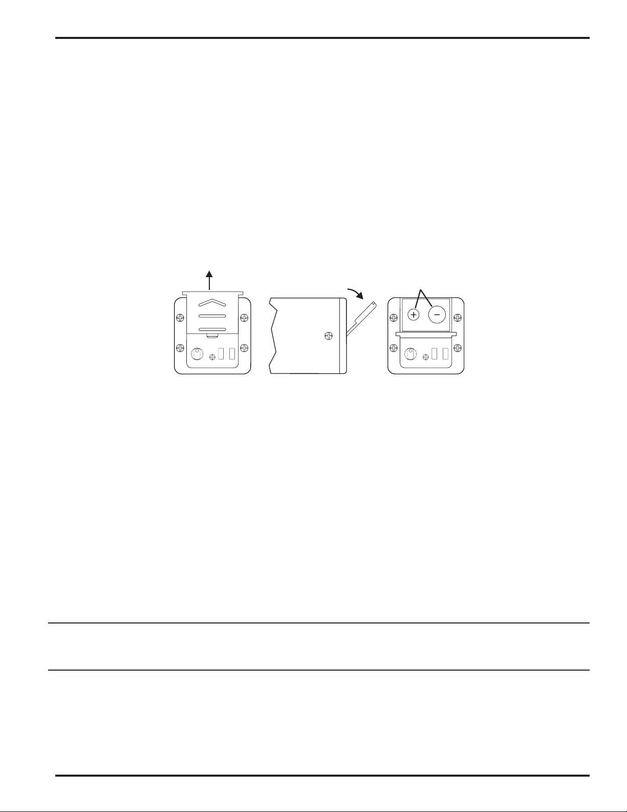
To open the battery compartment, press outward on the cover
door in the direction of the arrow as shown in the drawing. Only
slight, sliding pressure is needed to open and close the battery
door.
RELEASE OBSERVE
DOOR
SWING OPEN
Swing the door open and take note of the polarity marked inside
showing the location of the positive (+) and negative (-) terminals.
Insert the battery and close the cover by pressing in and across,
reversing the opening procedure outlined above. Note that the
battery door will NOT close if the battery is inserted incorrectly,
since the terminals will hit a protective polarity barrier.
Don’t force the battery door closed. If it is difficult to close, the
battery is in backwards.
The battery life will be affected by the amount of phantom power
supplied to any microphones that require it. A high drain 48 Volt
microphone can shorten battery life by 40% or more. A light drain
15 Volt microphone will make little or no difference in battery life.
The only way to be sure is to test the transmitter and microphone
combination with a brand new battery; then and only then will you
be sure of the combination's battery life.
POLARITY
Battery Compartment Action
CAUTION
Lithium batteries will expand and swell if allowed to go into a deep discharge. Be sure to remove lithium batteries as soon as the
display starts flashing DEAD BATTERY. If lithium batteries are allowed to fully discharge while still inside the battery compartment,
they will be very difficult to remove.
Stuck lithium batteries can be avoided by removing the label wrapping around the battery before use. This will allow the battery to
swell but will still leave enough room in the compartment for the battery to fall out normally.
TROUBLESHOOTING
Before going through the following chart, be sure that you have a good battery in the transmitter. It is important that you follow these
steps in the sequence listed.
SYMPTOM POSSIBLE CAUSE
TRANSMITTER BATTERY LED OFF 1. Battery is inserted backwards.
2. Battery is dead.
NO TRANSMITTER MODULATION LEDs 1. Gain control turned all the way down.
2. Battery is in backwards. Check power LED.
3. Mic capsule is damaged or malfunctioning.
4. Mic cable damaged or mis-wired.
5. Phantom power not enabled for mic that requires it.
Rio Rancho, NM – USA
7
Page 8

SYMPTOM POSSIBLE CAUSE
RECEIVER RF LAMP OFF 1. Transmitter not turned on.
2. Transmitter battery is dead.
3. Receiver antenna missing or improperly positioned.
4. Transmitter and receiver not on same frequency.
display on transmitter and receiver.
5. Operating range is too great.
NO SOUND (OR LOW SOUND LEVEL),
RECEIVER MOD LEVEL LEDs ARE ON 1. Receiver output level set too low.
2. Receiver output is disconnected; cable is defective or mis-wired.
3. Sound system input is turned down.
NO SOUND (OR LOW SOUND LEVEL),
RECEIVER MOD LEDs ARE OFF 1. Transmitter gain (audio level) set too low.
2. Faulty microphone
3. Phantom power not enabled for mic that requires it.
DISTORTED SOUND 1. Transmitter gain (audio level) is far too high. Check mod level
lamps on transmitter and receiver as it is being used. (Refer to
the Operating Instructions section for details on gain adjustment)
2. Receiver output may be mismatched with the sound system or
recorder input. Adjust output level on receiver to the correct level
for the recorder, mixer or sound system.
3. Excessive wind noise or breath “pops.”
and/or use a larger windscreen.
Check switches/
Reposition microphone
4. Transmitter is not set to same frequency as receiver. Check that
frequency select switches on receiver and transmitter match.
HISS AND NOISE – AUDIBLE DROPOUTS 1. Transmitter gain (audio level) far too low.
2. Receiver antenna missing or obstructed.
3. Operating range too great.
EXCESSIVE FEEDBACK 1. Transmitter gain (audio level) too high causing the limiter to reduce
the dynamic range which in turn causes feedback. Check gain
adjustment and/or reduce receiver output level. (Refer to the
Operating Instructions section for details on gain adjustment)
2. Transmitter too close to speaker system.
3. Mic is too far from user’s mouth.
8
Page 9

Frequency Agile Plug-on UHF Transmitter
SPECIFICATIONS AND FEATURES
Operating frequencies: 537.600 to 607.900 MHz
614.100 to 767.900 MHz
Frequency selection: 256 frequencies in 100kHz steps
RF Power output: 100 mW (nominal)
Pilot tone: 32.764 kHz (± 2Hz); 5kHz deviation
Frequency stability: ± 0.002%
Deviation: ± 75 kHz (max)
Spurious radiation: 90 dB below carrier at frequencies less than 1GHz
Equivalent input noise: -126 dBV
Phantom Power: Selectable 5 Volts at 8 mA, 15 Volts at 8 mA, 42 Volts at 4 mA or OFF
Input level: Nominal 2 mV to 300 mV, before limiting.
Input greater than 2V, with limiting.
Input impedance: 1K Ohm mic load impedance
Input compressor: Sof t compressor, >30 dB range
Gain control range: 43 dB; semi-log rotary control
Modulation indicators: Dual LEDs indicate modulation level 20 dB below limiting and at the
onset of limiting.
Controls: 3-position “OFF-PHANTOM-ON” slide switch for noiseless turn on/turn
off operation. Control panel knob adjusts audio gain. Rotary
switches on side panel adjust transmitter frequency. 3-position
voltage selector switch for 5, 15 or 48 Volt phantom mic power.
Audio Input Jack: 3-Pin XLR
Battery: Precision compartment auto-adjusts to accept any known alkaline
or lithium 9 Volt battery. (We’ve tried 150 different ones!)
Battery Life: 4.5 Hours with alkaline 9 Volt, 12 hrs with lithium (Battery life will
vary with battery brand, phantom power voltage setting and mic
current drain.)
Weight: 6.6 ozs. including battery
Dimensions: 1.5 x 1.5 x 4.2 inches
Emission Designator: 180KF3E
Specifications subject to change without notice.
Rio Rancho, NM – USA
9
Page 10

SERVICE AND REPAIR
If your system malfunctions, you should attempt to correct or isolate the trouble before concluding that the equipment needs repair.
Make sure you have followed the setup procedure and operating instructions. Check out the interconnecting cords and then go
through the TROUBLE SHOOTING section in the manual
We strongly recommend that you do not try to repair the equipment yourself and do not have the local repair shop attempt anything
other than the simplest repair. If the repair is more complicated than a broken wire or loose connection, send the unit to the factory
for repair and service. Don’t attempt to adjust any controls inside the units. Once set at the factory, the various controls and trimmers
do not drift with age or vibration and never require readjustment. There are no adjustments inside that will make a malfunction-
ing unit start working.
LECTROSONICS’ service department is equipped and staffed to quickly repair your equipment. In warranty repairs are made at no
charge in accordance with the terms of the warranty. Out of warranty repairs are charged at a modest flat rate plus parts and
shipping. Since it takes almost as much time and effort to determine what is wrong as it does to make the repair, there is a charge for
an exact quotation. We will be happy to quote approximate charges by phone for out of warranty repairs.
RETURNING UNITS FOR REPAIR
You will save yourself time and trouble if you will follow the steps below:
A. DO NOT return equipment to the factory for repair without first contacting us by letter or by phone. We need to know the nature of
the problem, the model number and the serial number of the equipment. We also need a phone number where you can be reached
8 am to 4 pm (Mountain Standard Time).
B. After receiving your request, we will issue you a return authorization number (R.A.). This number will help speed your repair
through our receiving and repair departments. The return authorization number must be clearly shown on the outside of the
shipping container.
C. Pack the equipment carefully and ship to us, shipping costs prepaid. If necessary, we can provide you with the proper packing
materials. UPS is usually the best way to ship the units. Heavy units should be “double-boxed” for safe transport.
D. We also strongly recommend that you insure the equipment, since we cannot be responsible for loss of or damage to equipment
that you ship. Of course, we insure the equipment when we ship it back to you.
Mailing address: Shipping address: Telephones:
Lectrosonics, Inc. Lectrosonics, Inc. Regular: (505) 892-4501
PO Box 15900 581 Laser Rd. Toll Free (800) 821-1121
Rio Rancho, NM 87174 Rio Rancho, NM 87124 FAX: (505) 892-6243
USA USA
World Wide Web: http://www.lectrosonics.com Email: sales@lectrosonics.com
10
Page 11

NOTES:
Frequency Agile Plug-on UHF Transmitter
Rio Rancho, NM – USA
11
Page 12

LIMITED ONE YEAR WARRANTY
LIMITED ONE YEAR WARRANTY
The equipment is warranted for one year from date of purchase against defects in
materials or workmanship provided it was purchased from an authorized dealer. This
warranty does not cover equipment which has been abused or damaged by careless
handling or shipping. This warranty does not apply to used or demonstrator equipment.
Should any defect develop, Lectrosonics, Inc. will, at our option, repair or replace any
defective parts without charge for either parts or labor. If Lectrosonics, Inc. cannot
correct the defect in your equipment, it will be replaced at no charge with a similar new
item. Lectrosonics, Inc. will pay for the cost of returning your equipment to you.
This warranty applies only to items returned to Lectrosonics, Inc. or an authorized
dealer, shipping costs prepaid, within one year from the date of purchase.
This Limited Warranty is governed by the laws of the State of New Mexico. It states the
entire liablility of Lectrosonics Inc. and the entire remedy of the purchaser for any
breach of warranty as outlined above. NEITHER LECTROSONICS, INC. NOR
ANYONE INVOLVED IN THE PRODUCTION OR DELIVERY OF THE EQUIPMENT
SHALL BE LIABLE FOR ANY INDIRECT, SPECIAL, PUNITIVE, CONSEQUENTIAL,
OR INCIDENTAL DAMAGES ARISING OUT OF THE USE OR INABILITY TO USE
THIS EQUIPMENT EVEN IF LECTROSONICS, INC. HAS BEEN ADVISED OF THE
POSSIBILITY OF SUCH DAMAGES. IN NO EVENT SHALL THE LIABILITY OF
LECTROSONICS, INC. EXCEED THE PURCHASE PRICE OF ANY DEFECTIVE
EQUIPMENT.
This warranty gives you specific legal rights. You may have additional legal rights which
vary from state to state.
LECTROSONICS, INC.
581 LASER ROAD
RIO RANCHO, NM 87124 USA
www.lectrosonics.com
July 31, 2003
 Loading...