

Page 1

UH190
Plug-on Transmitter
OPERATING INSTRUCTIONS
and trouble-shooting guide
LECTROSONICS, INC.
Rio Rancho, NM
Page 2

INTRODUCTION
Thank you for selecting the Lectrosonics UH190 belt-pack transmitter. The UH190
combines over 80 years of engineering experience with the very latest components,
in a design that addresses the most demanding professional applications.
The design of the UH190 was the direct result of numerous conversations with
users, staging and touring companies and dealers across the US. The specific
concerns and needs brought up in these conversations led directly to the development of the operational features offered on the UH190.
The UH190 is a rugged, machined aluminum package. 5 Volts of bias voltage is
available to power electret mics with either positive or negative bias. Level indicating
LEDs are provided to make level settings quick and accurate, without having to view
the receiver. The battery compartment accepts any 9 Volt alkaline battery and
makes a positive connection via self-adjusting contacts.
Only the UH190 transmitter is covered in this manual. Companion receivers are
covered in separate manuals. The UH190 will operate with any 190 Series Lectrosonics receiver on the same frequency.
TABLE OF CONTENTS
INTRODUCTION .................................................................................................. 2
GENERAL TECHNICAL DESCRIPTION ............................................................ 3
CONTROLS AND FUNCTIONS .......................................................................... 4
OPERATING INSTRUCTIONS ............................................................................ 5
BATTERY REPLACEMENT ................................................................................. 6
TROUBLESHOOTING ......................................................................................... 7
SPECIFICATIONS AND FEATURES................................................................... 8
SERVICE AND REPAIR ....................................................................................... 9
RETURNING UNITS FOR REPAIR ..................................................................... 9
WARRANTY ......................................................................................... Back cover
The UH190 transmitter is FCC type accepted under Part 74: 470-608 MHz
2
Page 3
Plug-on Transmitter
GENERAL TECHNICAL DESCRIPTION
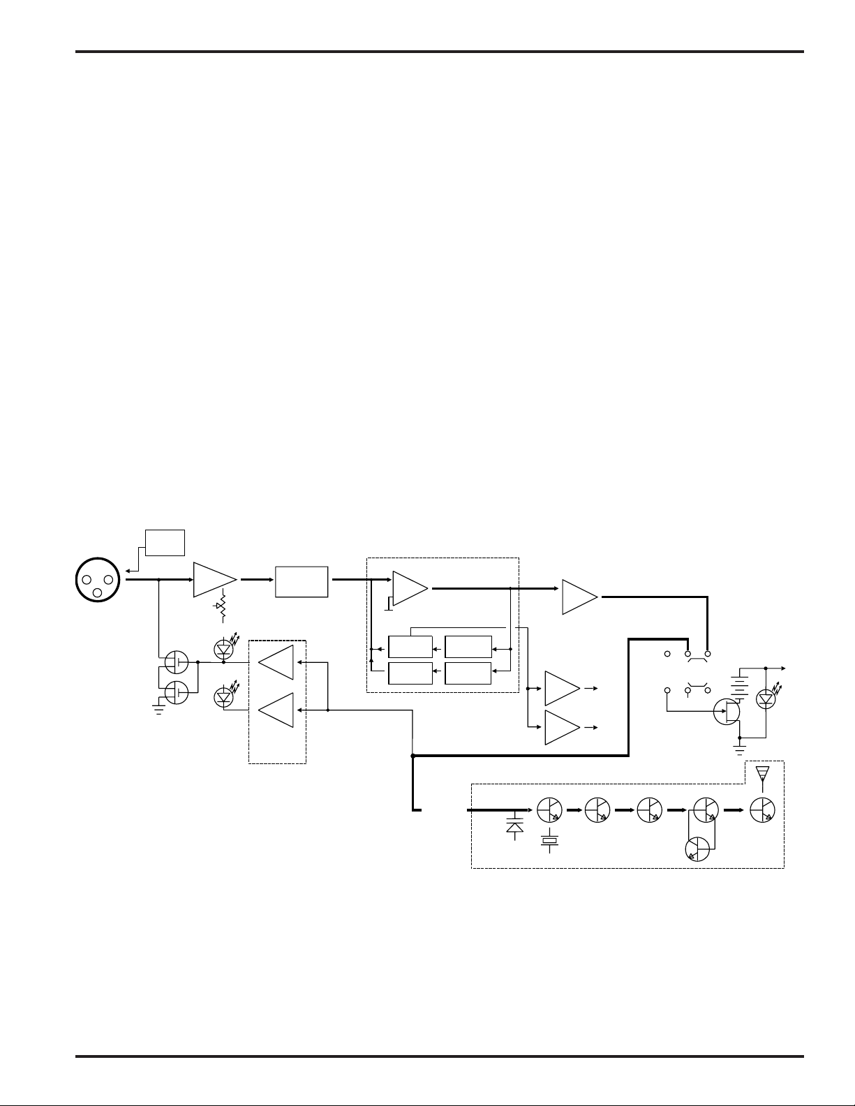
The UH190 transmitter is comprised of a number of functional subsystems as shown in the block diagram below.
The 190 system uses 15kHz deviation. The transmitter circuits are all regulated to allow full output power from the
beginning (9 Volts) to the end (7 Volts) of battery life. The oscillator crystal is shock mounted to provide ruggedness.
The input amplifier uses a Motorola 33078 op amp for ultra low noise operation. It is gain controlled with a wide
range input compressor which cleanly limits input signal peaks over 40dB above full modulation.
Traditionally, compandors have been a source of distortion in wireless microphone systems. The basic problem with
conventional systems is that the attack and decay times are always a compromise. If the time constants are fast,
high frequency transients will not be distorted, but this will cause low frequency distortion. If the time constants are
slower, low frequency audio distortion will be low, but high frequency transients will then be distorted. The 190
system introduces an entirely new approach to solving this basic problem, called “dual-band companding.”
There are actually two separate compandors in the 190 system, one for high frequencies and one for low frequencies. A crossover network separates the frequency bands at 1kHz with a 6dB per octave slope, followed by separate
high and low frequency compandors. The attack and release times in the high frequency compandor are fast enough
to keep high frequency transient distortion at a low level, and the low frequency compandor uses slower time constants, reducing low frequency distortion to well below that of a conventional compandor.
MIC
JACK
SHUNT
LIMITER
+5V BIAS
SUPPLY
INPUT
AMP
LIMIT
LED
SET
LED
AUDIO
LEVEL
FILTER
PEAK AUDIO
INDICATOR &
LIMITER
DRIVER
LP
COMPANDOR
Vref
BASS
TREBLE
LP FILTER
HP FILTER
COMPANDED
AUDIO
UH190 Block Diagram
Vreg
Vreg
XTAL OSC
+5VDC
+3.6VDC
X4
UHF TRANSMITTER
OFF
X2 X2 X2
ONMUTE
-9V
+9VDC
PWR
LED
Rio Rancho, NM – USA
3
Page 4
CONTROLS AND FUNCTIONS
TOP VIEW
CONTROL PANEL
LIMIT LED
LEVEL LED
LEVEL
OFF
MUTE
ON
BATTERY
POWER
LED
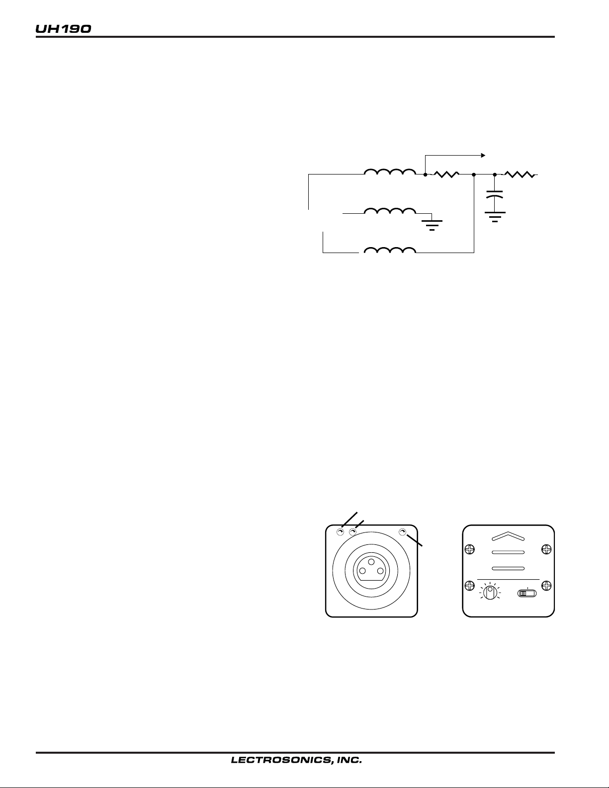
The UH190 may be used with a wide variety of microphones. The 3-pin XLR type connector on the UH190 allows
the transmitter to be used with any dynamic microphone, as well as many two wire positive bias lavalier systems
(such as those systems supplied by Lectrosonics).
INPUT JACK
Standard 3-pin Switchcraft XLR type. Pin 2 is signal, pin
3 is signal ground, and pin 1 is case ground (see schematic below). The UH190 is self-locking onto a standard
1uh
To Mic
Preamp
100
+5V
microphone. The XLR connector is permanently bonded
to the metal collar, and is not normally replaceable. The
electret bias is 5 Volts at 1mA or less. The bias is
connected in a “phantom” manner and will not interfere
with any standard balanced microphone. If severe noise
is experienced when the microphone is moved with
1uh
1
2
3
1uh
100uf
respect to the UH190, the cause is an unbalanced
condition between pins 2 and 3 of the microphone.
POWER/MUTE SWITCH
Turns the battery power on and off. The center position is an “audio mute” which should be used when setting the
MIC LEVEL control. The “mute” position disconnects the audio signal from the transmitter and allows you to adjust
the audio modulation level without the possibility of feedback. When turning the transmitter on, pause for a moment
in the “mute” position. This will prevent a turn-on surge from occurring (a “thump” sound).
POWER ON/OFF LED
Glows brightly when battery is good. A weak or dim LED means that the battery is weak, and has about an hour of
operation left. If the LED fails to light, the battery should be replaced. The power LED should light up in both the
“mute” and “on” positions of the POWER/MUTE SWITCH.
The POWER LED is connected to a precision battery test circuit that continuously monitors battery voltage. The
LED is at full brightness with a new 9 Volt alkaline battery. As the battery voltage drops during use, the LED brightness will also decrease. After 7 to 8 hours the battery voltage will be about 7 Volts. The LED will be completely
extinguished. Since the internal circuits are all tightly regulated and the RF output stage has a separate discrete
regulator, the transmitter will continue to operate to a battery voltage of 6.5 Volts. From 6.5 Volts to 6 Volts, the
transmitter will still operate, but with degraded performance. Please note that a weak battery will sometimes light the
POWER LED immediately after turn on, but soon will discharge to the point where the LED will extinguish.
The combination of an accurate battery condition indicator
and regulation of all internal circuits guarantees much longer
battery life, as well as consistent performance versus battery
life.
MODULATION LEDS: Indicate the proper setting of the MIC
LEVEL control.
LEVEL LED: Flickers or glows all the time if the audio volume
is adequate for normal operation.
LIMIT LED: Lights up when the audio volume is high, indicating that the signal level is being limited by the compressor.
Optimum signal-to-noise ratio is obtained when the limit LED
lights occasionally.
MIC LEVEL: Used to adjust the audio input volume for the proper modulation level. Rotate knob until the LEVEL
LED flickers when there is an input signal. The LIMIT LED should light occasionally.
4
Page 5

Plug-on Transmitter
OPERATING INSTRUCTIONS
1) Insert the UH190 into the selected microphone. Listen for the “click” that indicates the UH190 has locked on to
the microphone. Pull on the mic to insure proper locking has occurred.
2) Turn the power switch to the “MUTE” position on both the transmitter and the receiver. The “MUTE” position
allows internal voltages to stabilize before audio signal paths are opened.
3) Hold the microphone as you will when you will be using it.
4) Speak as loudly as you expect to speak in normal system use. Rotate the MIC LEVEL knob so that the LEVEL
LED flickers or stays lit as you speak. The LIMIT LED should light up on loud “peaks.”
LIMIT LED (about 10-15% of the time) indicates proper operation and optimum signal-to-noise ratio.
the transmitter is limiting, little distortion is produced because of the high linearity of the gain control circuit in the
UH190.
5) Move switches to “ON” position on both the transmitter and the receiver and adjust the volume of the
sound system.
NOTE:
The MIC LEVEL control should not be used to control the volume of your sound system. This is accomplished using
the level control on the receiver, or a level control on the mixing console.
Occasional lighting of the
Even when
If the mic level is too high - the LIMIT LED will light frequently or stay on. This condition may cause distortion.
TO ATTACH
PRESS FIRMLY, LISTEN FOR CLICK
DEPRESS COLLAR FULLY
PULL ON MIC TO INSURE LOCKING
TO REMOVE
ROTATE
COLLAR
If the mic level is too low - neither LED will light, or the LEVEL LED will light dimly. This condition will cause hiss and
noise. You may experience severe reduction in apparent range if the modulation level is too low. It may sound as if
you are getting dropouts. What is actually happening is that you are hitting your noise floor because the S/N ratio
has been compromised by the low modulation.
The LEVEL LED turns on at -12dB below full deviation. The LIMIT LED turns on at full deviation and indicates that
the input shunt compressor is operating. The input compressor operates over a full 30dB range regardless of the
gain control setting. The compressor uses a true absolute value circuit to detect both positive and negative peaks.
The attack time is 2 milliseconds and the release time is 80 milliseconds. Occasional limiting is desirable, indicating
that the gain is correctly set and the transmitter is fully modulated.
Rio Rancho, NM – USA
5
Page 6

BATTERY REPLACEMENT
The UH190 transmitter is powered by a standard alkaline 9 Volt battery. It is important that you use ONLY an ALKALINE battery for longest life. Standard zinc-carbon batteries marked “heavy duty” or “long-lasting” are not adequate.
They will provide only about 3 hours of operation. Similarly, nicad rechargeable batteries only give 3 hours of operation, and will also run down quite abruptly. Alkaline batteries provide about 7.5 hours of operation.
To open the battery compartment, press outward on the cover door in the direction of the arrow as shown in the
drawing. Only slight, sliding pressure is needed to open and close the battery door.
Swing the door open and take note of the polarity marked inside showing the location of the positive (+) and negative
(-) terminals. Insert the battery and close the cover by pressing in and across, reversing the opening procedure
outlined above. Note that the battery door will NOT close if the battery is inserted incorrectly, since the terminals will
hit a protective polarity barrier.
RELEASE
DOOR
SWING OPEN
OBSERVE
POLARITY
6
Page 7

TROUBLESHOOTING
Plug-on Transmitter
Before going through the following chart, be sure that you have a good battery in the transmitter the red power LED
on the transmitter panel should glow brightly.
SYMPTOM POSSIBLE CAUSE
NO AUDIO IS HEARD BUT RECEIVER 1) On/Off switch is in “mute” position
RF LED IS ON receiver or transmitter.
2) Microphone on/off switch is in “off” position.
NOTE: If the modulation level 3) Volume is turned down or off on
LEDs on the receiver are transmitter or receiver.
indicating properly, the problem 4) Receiver not properly connected to
is NOT in the transmitter. other audio equipment.
5) Transmitter POWER switch may be turned on and off (i.e.
through the mute position). A “thump” should be heard in the
sound, again indicating a properly functioning receiver.
NO SOUND IS HEARD AND RECEIVER 1) Transmitter not turned on. Check
RF LED IS OFF for power LED.
2) Receiver antenna may be defective or disconnected.
3) Transmitter and receiver frequencies don’t match. Check
frequency labels.
NOISE (HISS) IS HEARD ALONG 1) MIC LEVEL is too low (see page 5).
WITH THE SIGNAL 2) Transmitter and receiver may be too far from one another.
3) Receiver antenna may be defective or disconnected.
DISTORTED SOUND 1) MIC LEVEL is too high (see page 5).
2) Mic may be distorting; try a different mic and listen again.
3) PA system may be overloading.
EXCESSIVE FEEDBACK 1) MIC LEVEL may be set too high (see page 5).
2) Sound system volume set too high.
3) Microphone too far from the user’s mouth.
4) Loudspeakers may be too close to the mic.
Rio Rancho, NM – USA
7
Page 8

SPECIFICATIONS AND FEATURES
Operating frequencies: 470 to 608 MHz
RF Power output: 100 mW (nominal)
Frequency stability: ± 0.004%
Deviation: ± 15 kHz (max)
Spurious radiation: 50 dB below carrier
Equivalent input noise: -126 dBV
Pre-emphasis: 100us
Input level: Nominal 2 mV to 300 mV, before limiting.
Greater than 3 Volts maximum, with limiting.
Input compressor: Soft compressor, >40 dB range
Gain control range: 43 dB; semi-log rotary control
Modulation indicators: Dual LEDs indicate modulation level 12 dB below limiting and
at the onset of limiting.
Controls: 3 position “OFF-MUTE-ON” slide switch for noiseless turn on/turn off
operation. Control panel knob adjusts audio gain.
Battery: Precision compartment auto-adjusts to accept any known alkaline
9 Volt battery. (We’ve tried 108 different ones!)
Battery Life: 7.5 Hours with alkaline 9 Volt
Weight: 7 ozs. including battery
Dimensions: 1.5 x 1.5 x 4.2 inches
Emission Designator: 42K0F3E
Specifications subject to change without notice.
8
Page 9

Plug-on Transmitter
SERVICE AND REPAIR
If your system malfunctions, you should attempt to correct or isolate the trouble before concluding that the equipment
needs repair. Make sure you have followed the setup procedure and operating instructions. Check out the interconnecting cords and then go through the TROUBLE SHOOTING section in the manual
We strongly recommend that you do not try to repair the equipment yourself and do not have the local repair shop
attempt anything other than the simplest repair. If the repair is more complicated than a broken wire or loose connection, send the unit to the factory for repair and service. Don’t attempt to adjust any controls inside the units.
Once set at the factory, the various controls and trimmers do not drift with age or vibration and never require readjustment. There are no adjustments inside that will make a malfunctioning unit start working.
LECTROSONICS’ service department is equipped and staffed to quickly repair your equipment. In warranty repairs
are made at no charge in accordance with the terms of the warranty. Out of warranty repairs are charged at a
modest flat rate plus parts and shipping. Since it takes almost as much time and effort to determine what is wrong
as it does to make the repair, there is a charge for an exact quotation. We will be happy to quote approximate
charges by phone for out of warranty repairs.
RETURNING UNITS FOR REPAIR
You will save yourself time and trouble if you will follow the steps below:
A. DO NOT return equipment to the factory for repair without first contacting us by letter or by phone. We need to
know the nature of the problem, the model number and the serial number of the equipment. We also need a phone
number where you can be reached 8 am to 4 pm (Mountain Standard Time).
B. After receiving your request, we will issue you a return authorization number (R.A.). This number will help speed
your repair through our receiving and repair departments. The return authorization number must be clearly shown
on the outside of the shipping container.
C. Pack the equipment carefully and ship to us, shipping costs prepaid. If necessary, we can provide you with the
proper packing materials. UPS is usually the best way to ship the units. Heavy units should be “double-boxed” for
safe transport.
D. We also strongly recommend that you insure the equipment, since we cannot be responsible for loss of or damage
to equipment that you ship. Of course, we insure the equipment when we ship it back to you.
Mailing address: Shipping address: Telephones:
Lectrosonics, Inc. Lectrosonics, Inc. Regular: (505) 892-4501
PO Box 15900 581 Laser Rd. Toll Free (800) 821-1121
Rio Rancho, NM 87174 Rio Rancho, NM 87124 FAX: (505) 892-6243
USA USA
World Wide Web: http://www.lectrosonics.com Email: sales@lectrosonics.com
Rio Rancho, NM – USA
9
Page 10

LIMITED ONE YEAR WARRANTY
LIMITED ONE YEAR WARRANTY
The equipment is warranted for one year from date of purchase against defects in
materials or workmanship provided it was purchased from an authorized dealer. This
warranty does not cover equipment which has been abused or damaged by careless
handling or shipping. This warranty does not apply to used or demonstrator equipment.
Should any defect develop, Lectrosonics, Inc. will, at our option, repair or replace any
defective parts without charge for either parts or labor. If Lectrosonics, Inc. cannot
correct the defect in your equipment, it will be replaced at no charge with a similar new
item. Lectrosonics, Inc. will pay for the cost of returning your equipment to you.
This warranty applies only to items returned to Lectrosonics, Inc. or an authorized
dealer, shipping costs prepaid, within one year from the date of purchase.
This Limited Warranty is governed by the laws of the State of New Mexico. It states the
entire liablility of Lectrosonics Inc. and the entire remedy of the purchaser for any
breach of warranty as outlined above. NEITHER LECTROSONICS, INC. NOR
ANYONE INVOLVED IN THE PRODUCTION OR DELIVERY OF THE EQUIPMENT
SHALL BE LIABLE FOR ANY INDIRECT, SPECIAL, PUNITIVE, CONSEQUENTIAL,
OR INCIDENTAL DAMAGES ARISING OUT OF THE USE OR INABILITY TO USE
THIS EQUIPMENT EVEN IF LECTROSONICS, INC. HAS BEEN ADVISED OF THE
POSSIBILITY OF SUCH DAMAGES. IN NO EVENT SHALL THE LIABILITY OF
LECTROSONICS, INC. EXCEED THE PURCHASE PRICE OF ANY DEFECTIVE
EQUIPMENT.
This warranty gives you specific legal rights. You may have additional legal rights which
vary from state to state.
LECTROSONICS, INC.
581 LASER ROAD
RIO RANCHO, NM 87124 USA
November 1, 2001
 Loading...