

Page 1
UFM50
UHF Filter/Amplifier
Module
TECHNICAL DATA
Feature Highlights
• RF filtering before gain
• 50 MHz passband on center
frequencies from 560 to 865 MHz
• Ceramic resonator filters
• GasFET RF amplifier
• +41dBm 3rd Order Intercept
• Switching regulator for 8-16V power at
constant power dissipation to minimize
heat at high voltage
• Jumperable attenuators for +5dB, +8dB
and +12dB total gain
The UFM50 provides a unique, high performance solution for antenna systems requiring long cable runs or
distribution to multiple receivers or locations. The unit
can be used to apply RF gain at the antenna ahead of
a long run of coaxial cable to compensate for signal
loss through the cable. A compact, high performance
multicoupler can also be configured using the UFM50
ahead of an RF splitter to offset the loss through the
splitter.
The UFM50 design places RF filtering before gain to
minimize intermodulation (IM) products and prevent
overload. Two transmission line ceramic resonators at
the input provide filtering with a 50 MHz bandwidth.
Following the filters, 12dB of gain is applied with a high
quality GasFET RF amplifier with an excellent +41dBm
IP3. The result is outstanding RF performance without
IM or overload problems .
A switching regulator is used in the power supply to
control current consumption over an input voltage
range of 8 to 16 volts. The regulator maintains low
current consumption and low heat dissipation which is
especially useful in portable audio mixing common in
field production and ENG.
The UFM50 can be powered from external DC or via
phantom power through a coaxial cable connected to
the UMC16A Multicoupler.
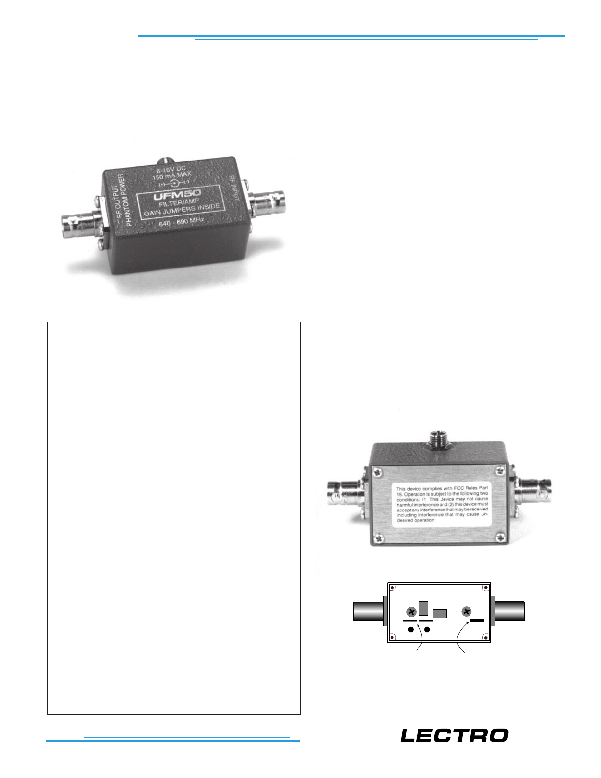
The housing is constructed of cast aluminum with a
brushed aluminum cover plate. Two rugged BNC connectors and a threaded, locking power jack provide
secure connections for rugged field conditions and for
long-term installations.
• Cast aluminum housing
• External power or phantom power at
output jack from UMC16A Multicoupler
• Includes 6 ft DC locking style mating
connector assembly for powering
STORE SPARES HERE
The gain of the RF amplifier can be adjusted with
internal attenuators for +5dB, +8dB and +12dB
total gain. Remove the four screws and the
bottom cover for access to the internal jumpers.
PLACE ACTIVE
ATTENUATOR HERE
T M
Page 2
UFM50 OPERATING INSTRUCTIONS
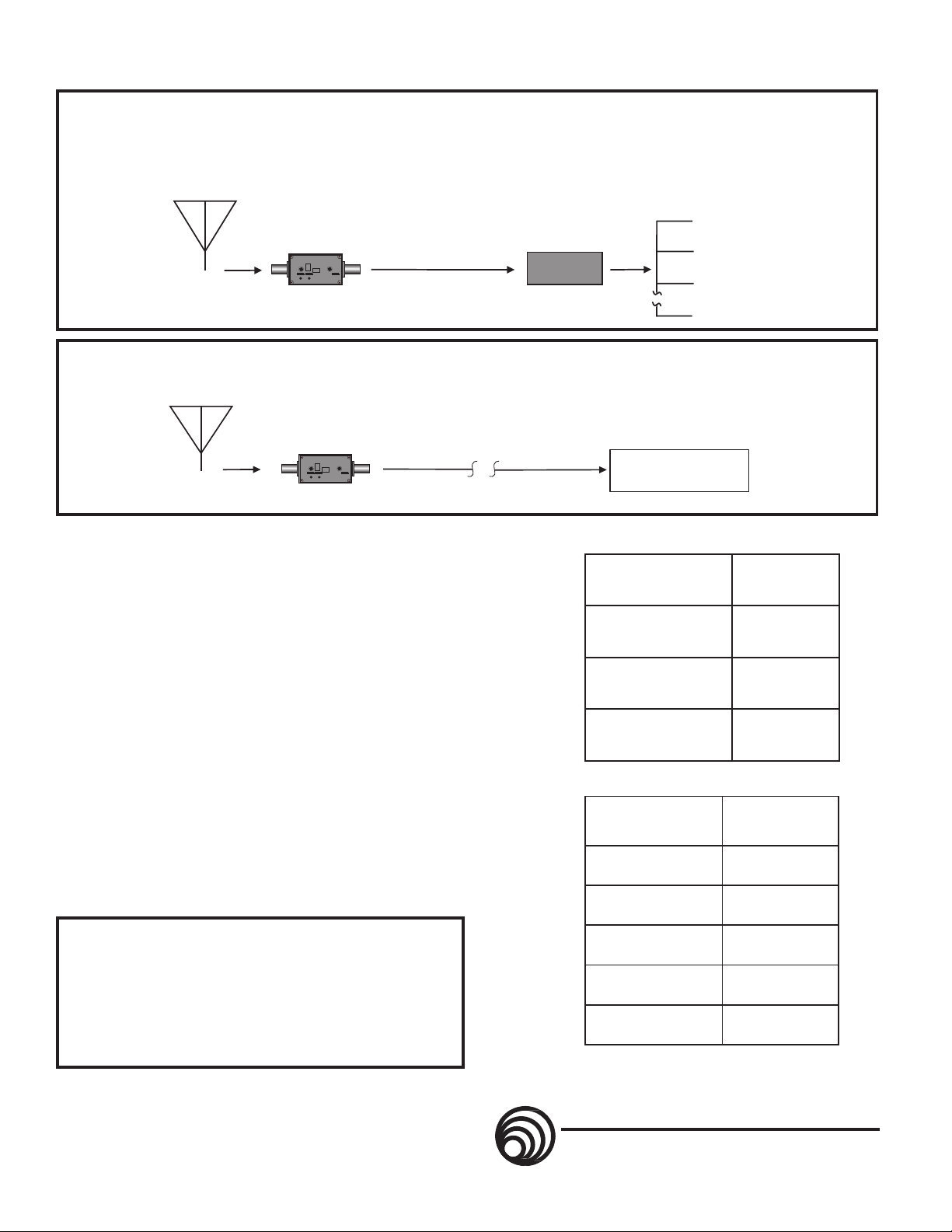
The UFM50 amplifier provides 12 dB of gain. By using the supplied attenuators, the gain can also be set to 8 dB or 5 dB . To determine
the correct amount of gain needed for a particular application, first determine the total loss in dB due to connectors, splitters, cabling, etc.
Then install the attenuator to set the gain in dB as close to the total loss figure as possible. Example #1 shows a 4-way passive splitter
ZFSC41) with 6 db of loss and a coax cable (ARG15) with 2 db of loss, for a total loss of 8 dB. In this case, the UFM50 should be used
with the 4 dB attenuator to produce the needed 8 dB of gain (12 - 4 = 8). The acceptable r ange is typically 0 to 3 dB of gain.
Multi-Cha n n el Systems
UFM50
Coaxial Cable
PASSIVE
SPLITTER
EXAMPLE 1
The UFM50 amplifier provides 12 dB of gain. This example sho ws the UFM50 used to offset the loss in a long coaxial cable (ARG100).
The cable presents 4.6 dB of loss, which can be rounded to 5 dB. This requires a gain of 5 dB to offset the loss in the cable . Using the
7 dB attenuator, you now hav e 5 dB of gain (12 -7 = 5) which is ideal.
Long Cable Runs
UFM50
Coaxial Cable
or Multi-coupler
EXAMPLE 2
RECEIVER
RECEIVER
RECEIVER
RECEIVER
Receiver
SPECIFICATIONS
Third Order Intercept: +27 dBm @ input (+41 dBm output)
Inputs: RF In - BNC
DC In - 2.1 mm locking power jack
Output: RF out - BNC (and phantom power in)
Freq Range: 560-865 MHz, factory set. See unit for
frequency range of your particular unit.
Filter Bandwidth: 50 MHz, factory set.
RF Gain: +12 dB with 0dB attenuator
+8 dB with 4dB attenuator
+5 dB with 7dB attenuator
Power Requirements: 8V DC (130 mA) up to 16 volts DC (70 mA)
at the DC input jack; Auto reset circuit breaker
Phantom Power: DC voltage supplied by UMC16A BNC input jack
or BIAS-T power inserter
Power Consumption: 1.075 Watts nominal (switching regulator)
Dimensions: 2.26 x 1.39 x 1.14 inches (not including BNCs)
Weight: 3.3 ozs
This product meets the CE Compliance Standards - EN55022
and EN50082-1:1998. A copy of the Declaration of Conformity
may be requested from your dealer or by contacting the factory
directly:
Lectrosonics, Inc.
Marketing Department
581 Laser Rd. NE, Rio Rancho, NM 87124 USA
tel: 505-892-4501 fax: 505-892-6243
e-mail: marketing@lectrosonics.com
scinosortceL
srettilpSevissaP
)yaw-2(42CSZBd3
)yaw-4(14CSFZBd6
)yaw-8(348CSFZBd9
scinosortceL
selbaCxaoC
2GRABd1
51GRABd2
52GRABd9.1
05GRABd8.2
001GRABd6.4
ssoL
ssoL
UFM50-12/00
LECTROSONICS
581 Laser Rd NE - Rio Rancho, NM - 87124 USA
(800)821-1121 (505)892-4501 Fax(505)892-6243
www.lectrosonics.com sales@lectrosonics.com
®
 Loading...