

Page 1

RARA
RA
RARA
TIOTIO
TIO
TIOTIO
UDR200AUDR200A
UDR200A
UDR200AUDR200A
DIVERSITYDIVERSITY
DIVERSITY
DIVERSITYDIVERSITY
RECEIVERRECEIVER
RECEIVER
RECEIVERRECEIVER
Wireless Diversity Receiver
OPERAOPERA
OPERA
OPERAOPERA
and trouble-shooting guideand trouble-shooting guide
and trouble-shooting guide
and trouble-shooting guideand trouble-shooting guide
LECTROSONICS, INC.LECTROSONICS, INC.
LECTROSONICS, INC.
LECTROSONICS, INC.LECTROSONICS, INC.
TING INSTRTING INSTR
TING INSTR
TING INSTRTING INSTR
Rio Rancho, NMRio Rancho, NM
Rio Rancho, NM
Rio Rancho, NMRio Rancho, NM
UCTIONSUCTIONS
UCTIONS
UCTIONSUCTIONS
Rio Rancho, NM – USA
1
Page 2

A little bit of Lectrosonics history...
Founded in 1971, Lectrosonics began with the manufacture of portable
sound systems sold under the Voice Projector© registered trademark. The
first product line consisted of a self-contained lectern/sound system and two
over-the-shoulder portable sound systems.
In 1975 the first wireless microphone systems were introduced to audio
visual markets. The first system was a lavalier system consisting of a beltpack transmitter and matching receiver. Soon after this, the receiver was
equipped with a rechargeable battery pack to allow it to be used with the
portable sound systems. A year or so later a special version of the receiver
was designed to be built inside of one of the lecterns providing a completely
cordless, wireless portable sound system in a lectern configuration. In
keeping with the "total portability" concept, the first self-contained speaker/
amplifier/wireless system was developed. The advent of wireless microphone
products introduced new prospective markets and set the stage for the future
direction of engineering. The first UNICHANNEL
with ultra-narrow band crystal IF filtering to eliminate interference.
By the early 1980's, wireless microphone products had come to dominate the
growth of the company, leading to further investment in engineering. The
first VHF high band wireless systems were introduced in 1987, taking the
©
proven UNICHANNEL
design to a higher frequency band. The product
line expanded rapidly over the following 5 or 6 years, leading to the
introduction of UHF wireless systems in 1993.
©
receiver was designed
In 1989 the first automatic mixer products were introduced. The most recent
models include an advanced microprocessor controlled mic/line mixer that
provides an adaptive algorithm* that keeps track of microphone activity to
prevent background noise from affecting the mixing action. Future products
in the audio group will include even more advanced microprocessor and
computer controlled components for automation of entire sound systems.
Lectrosonics remains an engineering driven company. Ongoing efforts
continuously produce new designs with the latest technology in electronics
and mechanical engineering.
*US Patent Pending
2
Page 3

Wireless Diversity Receiver
Table of Contents
FRONT PANEL CONTROLS AND FUNCTIONS ............................ 4
TRANSMITTER AUDIO LEVEL .............................................................................. 4
RF LEVEL INDICATORS ........................................................................................ 4
OPTI-BLEND LEDs ................................................................................................. 4
PILOT LED .............................................................................................................. 4
DIVERSITY MODE ................................................................................................. 4
MONITOR ............................................................................................................... 4
POWER ................................................................................................................... 4
REAR PANEL CONTROLS AND FUNCTIONS ............................... 5
AUDIO OUTPUT ..................................................................................................... 5
PHASE REV ............................................................................................................ 5
AC POWER SUPPLIES .......................................................................................... 5
EXTERNAL POWER JACK .................................................................................... 5
CONTACT CLOSURE ............................................................................................ 5
PILOT TONE BYPASS ........................................................................................... 5
ANTENNA JACKS .................................................................................................. 5
ANTENNA USE AND PLACEMENT ................................................ 6
INSTALLATION AND OPERATING INSTRUCTIONS ..................... 7
TROUBLESHOOTING ..................................................................... 8
POWER SUPPLY AND FUSE ................................................................................ 8
PILOT TONE SQUELCH ........................................................................................ 8
ANTENNAS AND RF SIGNAL STRENGTH ........................................................... 8
AUDIO SIGNAL QUALITY ...................................................................................... 8
UDR200 REPLACEMENT PARTS and ACCESSORIES ................ 9
SERVICE AND REPAIR ................................................................. 10
RETURNING UNITS FOR REPAIR ................................................ 10
SPECIFICATIONS AND FEATURES ............................................. 11
LIMITED ONE YEAR WARRANTY ................................................ 12
Rio Rancho, NM USA
–
3
Page 4
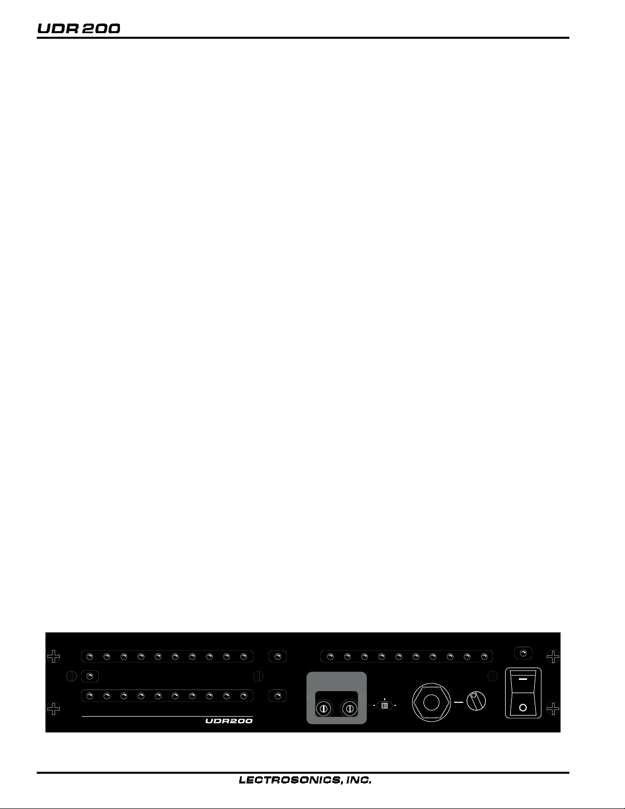
FRONT PANEL CONTROLS AND FUNCTIONS
TRANSMITTER AUDIO LEVEL
The modulation (audio level) of the incoming signal is indicated
by a fast responding LED strip. The strip is calibrated in 6dB
steps over an expanded scale (54dB) which provides an extremely accurate visual “picture” of the signal dynamics, even at
a distance away from the receiver. Audio signal peaks easily
exceed the response time of VU meters, however, the LED strip
is fast enough to track even brief transients.
RF LEVEL INDICATORS
Two separate LED strips are provided to indicate the level of the
incoming RF signals. The LED strips are calibrated to provide
accurate indications from 1uV to 1mV. The LEDs are highly
visible from a distance, making antenna set up more accurate.
The dual LED strips are especially useful in “trouble-shooting”
difficult antenna installations.
OPTI-BLEND LEDs
The UDR200 receiver operates with a method of audio ratio
blending of two audio outputs. RF level in each receiver is
compared and the audio signals from the two receivers are
mixed together in a ratio that favors the quieter receiver. As this
blending action occurs, the brightness of the two OPTI-BLEND
LEDs will vary. The brighter the LED, the more audio is being
mixed in from that receiver.
FREQUENCY SWITCHES
The UDR200 is frequency agile within the 5 MHz passband of
the front-end filters. To gain access to these switches, slide the
access door up with a fingernail. The left switch changes the
operating frequency by 1.6 MHz per step and the right switch
changes it 100 kHz per step. If you are experiencing interference, change the operating frequency in 100 kHz steps to find a
clear channel. If it is not possible to find a clear channel using
the 100 kHz switch, return it to its original position and change
the 1.6 MHz switch by one click then try the 100 kHz switch
again.
PILOT LED
The audio output muting (squelch) function of the UDR200 is
controlled by a 33kHz tone modulation of the RF carrier. The
audio output is muted until this tone is present. As soon as the
tone is received, this LED is turned on to indicate the audio
output is enabled.
The pilot tone function can be defeated by pressing a switch on
the rear panel. The PILOT LED, however, operates the same
regardless of whether or not the defeat switch is pressed. The
PILOT LED strictly indicates the presence of the pilot tone
carrier from the transmitter.
DIVERSITY MODE
This switch is set to the DIVERSITY position for normal operation. For trouble-shooting or when the receiver is used with a
single antenna, the switch can be set to select a single antenna
only.
MONITOR
This is an audio output to drive a wide variety of different types
of headphones. It is also useable as a secondary audio output to
drive recorders or external audio devices.
POWER
Pressing the upper half of the rocker switch applies power to
the receiver. At turn on, there are various relays and delays
built into the receiver to allow various stages to stabilize
before the audio output is activated. This will prevent an
audio “thump” when powering up the receiver and/or the
transmitter.
1uV
LECTROSONICS
5
2uV 1mV
PILOT
25
10
Figure 1 - UDR200 Front Panel
4
100
50
RF LEVEL
250
500
A
B
OPTI
BLEND
-42
-48
FREQUENCY
1.6M
100K
-36
TX AUDIO LEVEL dB
DIVERSITY
A B
MODE
POWER
-18-24-30
LIM0-6-12
MONITOR
Page 5
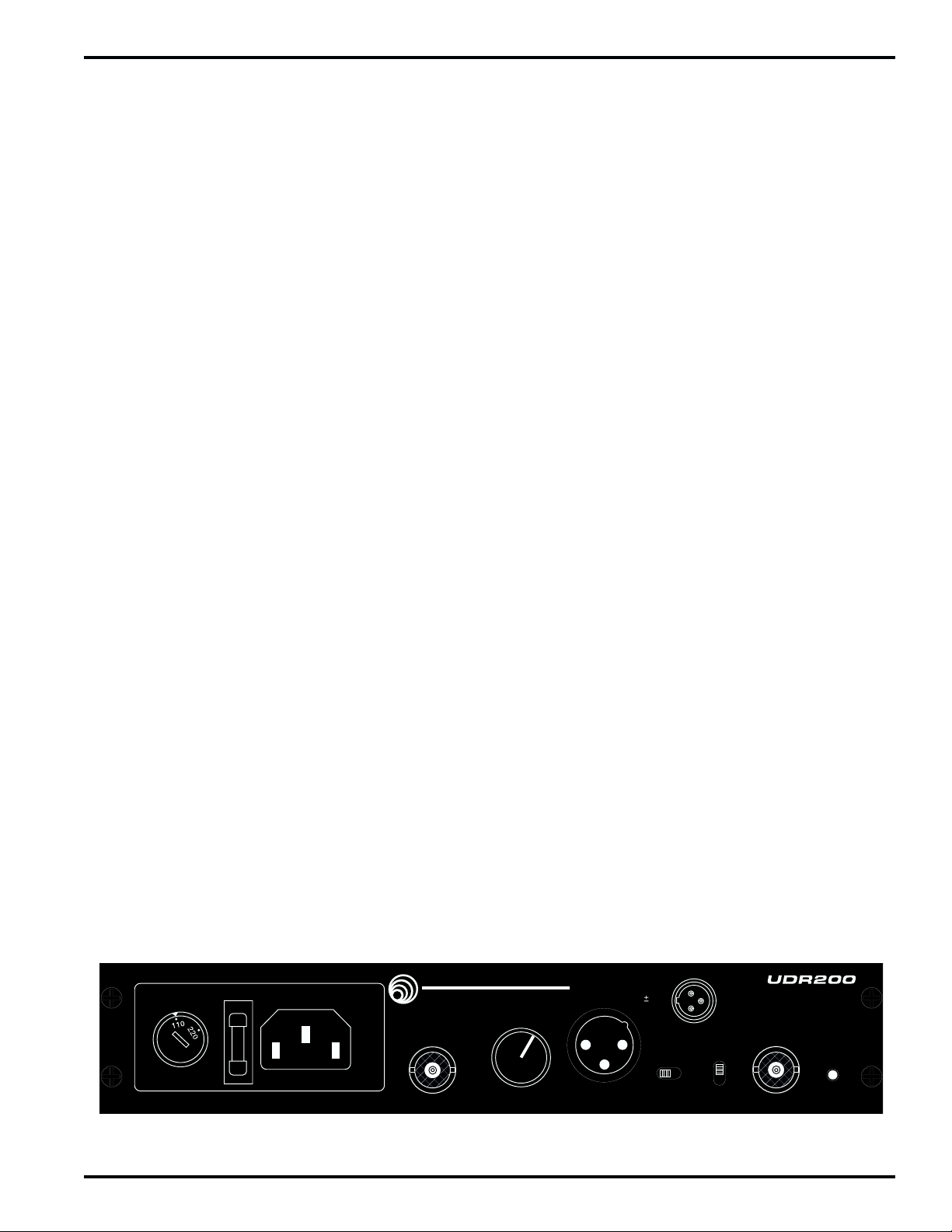
REAR PANEL CONTROLS AND FUNCTIONS
AUDIO OUTPUT DC IN
A calibrated control on the rear panel adjusts the output level in
5 dB steps, referenced in dBu. This control knob adjusts the
absolute output level at the XLR connector. The AUDIO OUTPUT level control is located after the output transformer. This
allows the signal to noise ratio to remain constant regardless of
the setting of the control. As the audio level is reduced, the
noise is also reduced maintaining the same ratio.
PHASE REV
This switch reverses the polarity of the audio output signal.
AC POWER SUPPLIES
The UDR200 can be powered from conventional 110 or 220 Volt
AC supplies via an internationally approved connector. A standard grounded socket, fuseholder and voltage selector switch are
combined into a single assembly. The fuseholder also contains a
spare fuse. To remove the fuseholder, simply pry it out with a
screwdriver or similar tool (it pulls straight outward from the
assembly). To select the operating voltage, disconnect the AC
power and then turn the voltage selector (located to the left of the
fuse) using a flatblade screwdriver or other similar tool so that the
desired voltage is lined up with the mark at the top.
The receiver can be powered from external 12 to 14 Volt DC
sources via the three pin jack. Pin 1 is GND, Pin 2 is +12V,
and Pin 3 is –12V. The relays and power supply stage are
fully protected by automatic reset poly fuses. The ground side
of the power supply is protected with a self resetting poly fuse
in case the UDR200 is connected to a positive ground device
through the audio cabling. The poly fuse will trip to protect
the receiver and the offending ground path can then be
removed.
PILOT TONE BYPASS
This switch defeats the audio output muting and triggering
action of the pilot tone. When the pilot tone is bypassed, the
Opti-Blend and the Variable Cutoff Low Pass Filter will still
provide a squelching action during weak signal conditions.
These circuits will provide approximately 50 dB of muting
when the pilot tone is bypasssed.
NOISE FILTER
A dynamic noise reduction filter can be switched in to minimize
excessive high frequency audio noise present in the acoustic
environment, or generated by the RF link in difficult environments or operating distances.
Wireless Diversity Receiver
BUSS: GDC 315mA (160mA) LITTLEFUSE: T-315mA (160mA) (218)
ANTENNA JACKS
These are standard 50 Ohm BNC terminals for the RF input to
the receiver.
LECTROSONICS
RIO RANCHO, NM - (800) 821-1121
ANT B
-15
-10
-20
-25
dBu
0
-5
5
-35
-30
M
1
10
15
-40
AUDIO OUTPUT
3
DC IN
14.4V
2
3
3: –12
2:
+
12
MAX
PHASE PILOT
0 180
2
1
NOISE
FILTER
OUT
1: GND
ANT A
RECEIVER
BYPASS
Figure 2 - UDR200 Rear Panel
Rio Rancho, NM – USA
5
Page 6

ANTENNA USE AND PLACEMENT
There are two remote antenna assemblies included with this
receiver. Position the antennas at least three or four feet apart
and so that they are not within 3 or 4 feet of large metal surfaces.
If this is not possible, try to position the antennas so that they are
as far away from the metal surface as is practical. It is also good
to position the receiver so that there is a direct “line of sight”
between the transmitter and the receiver antenna. In situations
where the operating range is less than about 50 feet, the antenna
positioning is much less critical. The antennas can also be
configured with one whip mounted directly onto the rear panel
of the UDR200 receiver, and the other one mounted remotely.
A wireless transmitter sends a radio signal out in all directions.
This signal will often bounce off nearby walls, ceilings, etc. and
a strong reflection can arrive at the receiver antenna along with
the direct signal. If the direct and reflected signals are out of
phase with each other a cancellation may occur. The result
would be a “drop-out.” A drop-out sounds like either audible
noise (hiss), or in severe cases, may result in a complete loss of
the carrier and the sound when the transmitter is positioned in
certain locations in the room. A drop-out normally sounds like
“hiss” or a “swishing” sound. Moving the transmitter even a
few inches will change the sound of the hum or hiss, or eliminate it. A drop-out situation may be either better or worse as the
crowd fills and/or leaves the room, or when the transmitter or
receiver is operated in a different location.
The UDR200 receiver offers a sophisticated diversity design
which overcomes drop-out problems in almost any imaginable
situation. In the event, however, that you do encounter a dropout problem, first try moving the antenna at least 3 or 4 feet from
where it was. This may alleviate the drop-out problem on that
antenna. If drop-outs are still a problem, try moving the antenna
to an entirely different location in the room or moving the
antennas in closer to the transmitter location. By observing the
OPTI-BLEND LEDs on the front panel, you can determine
which antenna is suffering weak signals.
Lectrosonics transmitters radiate power very efficiently, and the
receivers are very sensitive. This reduces drop-outs to an insignificant level. If, however, you do encounter drop-outs frequently, call the factory or consult your dealer. There is probably
a simple solution.
RANSMITTER
PHASE
CANCELLATION
REFLECTIVE SURFACE
INDIRECT SIGNAL
DIRECT SIGNAL
DIRECT SIGNAL
RECEIVER
INDIRECT SIGNAL
MULTI-PATH DROPOUT
Figure 3 - Drop-outs
6
Page 7

Wireless Diversity Receiver
INSTALLATION AND OPERATING INSTRUCTIONS
1) If operating the unit from AC power, determine the line
voltage to be used and set the Line Voltage Selector on the
rear panel to match. The units are shipped with the proper
size fuse for use with 120V systems (315mA). If the unit will
be used in a 220V environment, change the fuse to a 160mA
of the same type. See the section “UDR200 Replacement
Parts and Accessories” for manufacturer part numbers of the
correct type and value for 110 and 220 Volt supplies.
2) Locate a suitable operating location where the receiver will
not be subjected to extreme temperature variations and possible bumps and drops. Try to route all wiring so it will not
cross walkways or isles.
3) Connect the power. For 120V AC operation, connect the
power cord to the AC input jack on the rear panel and plug the
other end into a suitable electrical outlet. If 12 to 14 Volt DC
operation is desired, a power cord will need to be fabricated.
Use a three-pin connector for the UDR200 end and wire the
+12 to pin 2, –12 to pin 3, and Gnd to pin 1. Make the length
of the DC cable long enough to suit your installation and
prepare and connect the source end of the cable.
4) Attach the antenna cables to the BNC jacks on the rear of the
UDR200 and place the antennas. Best performance will be
obtained if the antennas are placed at least 3 feet from each
other. Try to mount them as high as possible with a direct line
of sight path to the transmitter.
5) Set the Audio Output level control to minimum (CCW) and
connect the Audio Output XLR jack to the mixer input. Pins
2 and 3 of the XLR jack are HI and LO and can be reversed
with the Phase switch, pin 1 is common.
6) Preset the following controls:
MODE (front panel) to DIVERSITY
MONITOR (front panel) to minimum (CCW)
PHASE (rear panel) to 0
AUDIO OUTPUT (rear panel) to -40 (full CCW)
7) Turn the unit on with the front panel Power switch and check
to see that the red Pilot LED is off (be sure the transmitter is
turned off.)
8) Turn on the transmitter and adjust the transmitter gain. This
is perhaps the most important step in the setup procedure.
Adjust the transmitter so that voice peaks will light
the 0 LED on the UDR200 front panel Transmitter Audio
Level dB strip. The red LIM LED on the transmitter may
flash occasionally. This is normal but it should not happen
very often. See your transmitter manual (Operating Instructions section) for specific directions on how to adjust the gain
of your particular transmitter.
9) After adjusting the transmitter gain, set the rear panel Audio
Output level control to the desired level. The -40 setting is
approximately equal to 10mV, the 0 position will give
0.775VRMS, and the +15 setting will allow up to 4.4 VRMS.
This setting will depend on the requirements of your system.
10) Operate the system and re-adjust the receiver output level as
required for your equipment. The input levels on different
VCR’s and PA equipment vary, which may require that you
set the Audio Output control in an intermediate position. Try
different settings and listen to the results. If the output of the
receiver is too high, you may hear distortion or a loss of the
natural dynamics of the audio signal. If the output is too low,
you may hear steady noise (hiss) along with the audio.
11) Set the operating frequency. The left switch changes the
operating frequency by 1.6 MHz per step and the right switch
changes it 100 kHz per step. If you are experiencing interference, change the operating frequency in 100 kHz steps to find
a clear channel. If it is not possible to find a clear channel
using the 100 kHz switch, return it to its original position and
change the 1.6 MHz switch by one click then try the 100 kHz
switch again.
To gain access to these switches, slide the access door up with
a fingernail.
The UDR200 is frequency agile within the 5 MHz passband
of the front-end filters. It is possible to choose a frequency
that is outside the passband of the front-end filters. Reduced
operating range and increased noise can result if the receiver
is operating outside of its range.
We recommend that you never set the 1.6MHz switch more
than one click from the default position
Each receiver is factory aligned at the center of its operating
range. The default position of the frequency select switches
is in the center of the receiver passband.
0
1
F
E
D
C
B
A
2
3
4
5
6
9
7
8
0
1
F
E
D
C
B
A
2
3
4
5
6
9
7
8
Figure 4 - Frequency Select Switches, Default Position
Rio Rancho, NM – USA
7
Page 8

TROUBLESHOOTING
POWER SUPPLY AND FUSE
LEDs not lit or dimly lit — When the UDR200 is powered from an
external DC supply, the LEDs are dimmed to conserve battery life.
• AC power cord disconnected.
• External power supply disconnected or inadequate.
• Main power supply fuse blown.
• For 110 Volt operation: 315 mA, 250 Volt
Buss GDC-315 or Littlefuse 218.315
(Lectrosonics part #22090)
• For 220 Volt operation: 160mA, 250 Volt
Buss GDC-160 or Littlefuse 218.160
(Lectrosonics part #22091)
• Rear panel voltage selector incorrectly set.
PILOT TONE SQUELCH
The PILOT indicator lamp on the front panel lights up to indicate
that the audio has been turned on at the transmitter, and that the
audio output on the receiver is enabled. When the lamp is on, the
audio is on. When the lamp is off, the audio is muted.
PILOT lamp on, but no sound
• Audio output cable bad or disconnected. Try monitoring at the
headphone output on the front panel. The headphone out-
put signal is taken just ahead of the output transformer.
• AUDIO OUTPUT level set too low.
PILOT lamp off, but sound still comes through
• PILOT TONE BYPASS switch may have been pressed. Turn
receiver power off and then back on again to reset the audio
output relays.
PILOT lamp does not come on when transmitter audio switch is
turned on
• It takes several seconds for the relay to actuate the PILOT
lamp. Turn the transmitter power and audio switches on and
wait 2 to 5 seconds for the lamp to come on.
ANTENNAS AND RF SIGNAL STRENGTH
RF LEVEL is weak on one (or both) channels
• Antenna is disconnected or there is a bad connection
• Antenna may need to be moved or re-oriented
• Improper length of antenna, or wrong antenna. UHF whip
antennas should be about 5 to 6 inches long. VHF whip antennas should be about 14 to 20 inches long.
• Operating frequency is outside the passband of the receiver.
Check the frequency range of the unit and be sure the frequency
switches are not set beyond the limits of the receiver. (See step
11 on page 7 for more info.)
One OPTI BLEND LED does not come on or is dimly lit
• DIVERSITY switch is set to one or the other channels. Needs
to be in the center position for normal operation.
• Reverse the antennas on the rear panel inputs. If the opposite
OPTI BLEND LED now indicates the same problem, there may
be an antenna or cabling problem. Try re-positioning the
antenna(s).
AUDIO SIGNAL QUALITY
Poor signal to noise ratio
• Transmitter gain set too low
• Noise may not be in wireless system. Mute the audio signal at
the transmitter and see if noise remains. If the noise remains,
then turn the power off at the transmitter and see if it remains. If
the noise is still present, then the problem is not in the transmitter.
• If noise is still present when the transmitter is turned off, try
lowering the audio output level on the UDR200 rear panel and
see if the noise lowers correspondingly. If the noise remains,
the problem is not in the receiver.
• Receiver output does not match the input of the device it is
feeding. Try increasing the output level of the UDR200 and
lowering the input gain on the device the UDR200 is feeding.
Distortion
• Transmitter input gain too high. Check and/or re-adjust input
gain on transmitter according to the LEDs on the transmitter
and then verify the setting with the transmitter audio level LED
strip on the UDR200 front panel.
• Audio output level too high for the device the UDR200 is
feeding.
8
Page 9

Wireless Diversity Receiver
UDR200 REPLACEMENT PARTS and ACCESSORIES
Part No. Description
A-185-BNC Telescoping 1/4 wave VHF/UHF whip; BNC connector.
A-200 Remote dipole UHF/VHF antenna with aluminum mounting
block; supplied with one built-in telescoping whip and one
detachable telescoping whip. Operates on VHF or UHF
frequencies.
A-9775 Coaxial extension cable for A-200 dipole antenna; BNC male/
male connectors, 10 ft,
RG-58 cable.
21475 Replacement power cord
22090 Replacement fuse, GDC, 315ma, 250V
22091 Replacement fuse, GDC, 160mA, 250V
Rio Rancho, NM – USA
9
Page 10

SERVICE AND REPAIR
If your system malfunctions, you should attempt to correct or isolate the trouble before
concluding that the equipment needs repair. Make sure you have followed the setup procedure
and operating instructions. Check out the inter-connecting cords and then go through the
TROUBLE SHOOTING section in the manual
We strongly recommend that you do not try to repair the equipment yourself and do not have
the local repair shop attempt anything other than the simplest repair. If the repair is more
complicated than a broken wire or loose connection, send the unit to the factory for repair and
service. Don’t attempt to adjust any controls inside the units. Once set at the factory, the
various controls and trimmers do not drift with age or vibration and never require readjustment.
There are no adjustments inside that will make a malfunctioning unit start working.
LECTROSONICS service department is equipped and staffed to quickly repair your equipment. In-warranty repairs are made at no charge in accordance with the terms of the warranty.
Out of warranty repairs are charged at a modest flat rate plus parts and shipping. Since it takes
almost as much time and effort to determine what is wrong as it does to make the repair, there
is a charge for an exact quotation. We will be happy to quote approximate charges by phone for
out of warranty repairs.
RETURNING UNITS FOR REPAIR
You will save yourself time and trouble if you will follow the steps below:
A. DO NOT return equipment to the factory for repair without first contacting us by letter or by
phone. We need to know the nature of the problem, the model number and the serial number
of the equipment. We also need a phone number where you can be reached 8 am to 4 pm
(Mountain Standard Time).
10
B. After receiving your request, we will issue you a return authorization number (R.A.). This
number will help speed your repair through our receiving and repair departments. The
return authorization number must be clearly shown on the outside of the shipping container.
C. Pack the equipment carefully and ship to us, shipping costs prepaid. If necessary, we can
provide you with the proper packing materials. UPS is usually the best way to ship the units.
Heavy units should be “double-boxed” for safe transport.
D. We also strongly recommend that you insure the equipment, since we cannot be responsible
for loss of or damage to equipment that you ship. Of course, we insure the equipment when
we ship it back to you.
Mailing address: Shipping address: Telephones:
Lectrosonics, Inc. Lectrosonics, Inc. Regular: (505) 892-4501
PO Box 15900 581 Laser Rd. Toll Free (800) 821-1121
Rio Rancho, NM 87174 Rio Rancho, NM 87124 FAX: (505) 892-6243
USA USA
Web: http://www.lectrosonics.com Email: sales@lectrosonics.com
Page 11

SPECIFICATIONS AND FEATURES
Wireless Diversity Receiver
Operating Frequencies:
Frequency Adjustment Range:
Receiver Type:
Frequency Stability:
Front end selectivity:
Sensitivity
20 dB Sinad:
60 dB Quieting:
Squelch quieting:
AM rejection:
Modulation acceptance:
Image and spurious rejection:
Third order intercept:
Diversity technique:
FM Detector:
Antenna inputs:
Audio outputs
Rear Panel XLR:
Monitor out:
Front Panel Controls and Indicators:
Rear Panel Controls and features:
Power Options:
Weight:
Dimensions:
512 to 608 MHz, 614 to 806 MHz
4.7 MHz
Dual conversion, superheterodyne
±0.002 %
>22 dB at ±4 MHz
0.707 uV (-110 dBm), A weighted
0.63 uV (-111 dBm), A weighted
Greater than 125 dB
Greater than 60 dB, 2 uV to 1 Volt (Undetectable after processing)
>90 kHz
>120 dB
–10 dBm
Ratio diversity. Dual simultaneous receivers with dynamic audio
combining (Opti-blend).
Digital Pulse Counting Detector
Dual BNC female; 50 Ohm impedance
600 Ohm Balanced, transformer isolated, adjustable from -45 dBu to
+15 dBu in 5 dB steps, at 60 kHz deviation
Front panel ¼” Phone jack, adjustable from 0 to 635 mV RMS into 8
Ohms at 60 kHz deviation; 0 to 5.7V RMS into 600 Ohms at 60 kHz
deviation.
Power on/off switch and LED; Dual 10 segment RF signal level
display; 10 segment transmitter audio level display; Coarse and fine
frequency select controls; Diversity operation selector switch; OptiBlend operation LEDs; Pilot tone indicator; Monitor output jack and
level control.
Ant A and Ant B BNC connectors; Pilot tone bypass switch; Audio
phase reversal switch; Noise filter bypass switch; XLR audio output
jack and 12-step audio attenuator; External ±12VDC input; 120/240
VAC input jack with integral voltage selector switch and fuse.
120/240 VAC, 50/60 Hz, 10 Watts
±12V DC, +325mA/–120mA
4 lbs, 7 ozs
8.2" wide x 2.1" high x 10.6" deep
Rio Rancho, NM – USA
11
Page 12

LIMITED ONE YEAR WARRANTY
The equipment is warranted for one year from date of purchase against defects in materials or
workmanship provided it was purchased from an authorized dealer. This warranty does not
cover equipment which has been abused or damaged by careless handling or shipping. This
warranty does not apply to used or demonstrator equipment.
Should any defect develop, we will, at our option, repair or replace any defective parts without
charge for either parts or labor. If we cannot correct the defect in your equipment, we will
replace it at no charge with a similar new item. We will pay for the cost of returning your
merchandise to you.
This warranty applies only to items returned to us, shipping costs prepaid, within one year from
the date of purchase.
This warranty gives you specific legal rights. You may have additional legal rights which vary
from state to state.
LECTROSONICS, INC.
581 LASER ROAD
RIO RANCHO, NM 87124 USA
12
July 6, 1999
 Loading...