

Page 1

UDR195UDR195
UDR195
UDR195UDR195
RARA
TIO DIVERSITY RECEIVERTIO DIVERSITY RECEIVER
RA
TIO DIVERSITY RECEIVER
RARA
TIO DIVERSITY RECEIVERTIO DIVERSITY RECEIVER
Wireless Diversity Receiver
OPERAOPERA
OPERA
OPERAOPERA
and trouble-shooting guideand trouble-shooting guide
and trouble-shooting guide
and trouble-shooting guideand trouble-shooting guide
LECTROSONICS, INC.LECTROSONICS, INC.
LECTROSONICS, INC.
LECTROSONICS, INC.LECTROSONICS, INC.
TING INSTRTING INSTR
TING INSTR
TING INSTRTING INSTR
Rio Rancho, NMRio Rancho, NM
Rio Rancho, NM
Rio Rancho, NMRio Rancho, NM
UCTIONSUCTIONS
UCTIONS
UCTIONSUCTIONS
Rio Rancho, NM – USA
1
Page 2

Table of Contents
INTRODUCTION TO THE 195 SYSTEM ......................................... 4
MODULAR DESIGN ............................................................................................... 4
T195 TRANSMITTER ............................................................................................. 5
M195 TRANSMITTER ............................................................................................ 5
DUAL-BAND COMPANDOR .................................................................................. 5
75KHz DEVIATION ................................................................................................. 5
NO PRE-EMPHASIS/DE-EMPHASIS .................................................................... 5
EXCEPTIONAL THERMAL STABILITY ................................................................. 5
GENERAL TECHNICAL DESCRIPTION ......................................... 6
MODULAR UHF/VHF RF SECTION ...................................................................... 6
SIX-POLE HELICAL RESONATOR FRONT-END ................................................. 6
GaAs FET FRONT-END FILTER COUPLING ....................................................... 6
DOUBLE BALANCED DIODE MIXERS ................................................................. 6
8 POLE LINEAR PHASE FILTER ........................................................................... 6
DIGITAL PULSE COUNTING DETECTOR ............................................................ 7
RATIO COMBINING DIVERSITY WITH OPTI-BLEND .......................................... 7
2:1 EXPANDER (Dual–Band Compandor) ............................................................. 7
VARIABLE CUTOFF LOW PASS FILTER ............................................................. 7
PILOT TONE MUTE (SQUELCH) .......................................................................... 7
FRONT PANEL CONTROLS AND FUNCTIONS ............................ 8
AUDIO OUTPUT LEVEL ......................................................................................... 8
TRANSMITTER AUDIO LEVEL .............................................................................. 8
RF LEVEL INDICATORS ........................................................................................ 8
OPTI-BLEND LEDs ................................................................................................. 8
PILOT LED .............................................................................................................. 9
DIVERSITY MODE ................................................................................................. 9
MONITOR ............................................................................................................... 9
POWER ................................................................................................................... 9
REAR PANEL CONTROLS AND FUNCTIONS ............................. 10
VU METER HEADROOM ..................................................................................... 10
AUDIO OUTPUT ................................................................................................... 10
PHASE REV .......................................................................................................... 10
AC POWER SUPPLIES ........................................................................................ 10
EXTERNAL POWER JACK .................................................................................. 11
CONTACT CLOSURE .......................................................................................... 11
PILOT TONE BYPASS ......................................................................................... 11
ANTENNA JACKS ................................................................................................ 11
2
Page 3

Wireless Diversity Receiver
ANTENNA USE AND PLACEMENT .............................................. 12
INSTALLATION AND OPERATING INSTRUCTIONS ................... 13
TROUBLESHOOTING ................................................................... 14
POWER SUPPLY AND FUSE .............................................................................. 14
PILOT TONE SQUELCH ...................................................................................... 14
ANTENNAS AND RF SIGNAL STRENGTH ......................................................... 14
AUDIO SIGNAL QUALITY .................................................................................... 15
VU METERING AND OUTPUT LEVEL ................................................................ 15
DR195 REPLACEMENT PARTS and ACCESSORIES................. 15
SPECIFICATIONS AND FEATURES ............................................. 16
SERVICE AND REPAIR ................................................................. 17
RETURNING UNITS FOR REPAIR ................................................ 17
WARRANTY .................................................................... Back cover
Rio Rancho, NM – USA
3
Page 4

INTRODUCTION TO THE 195 SYSTEM
The DR195 employs the most advanced circuit and mechanical design ever applied to a wireless microphone receiver.
Two independent, ultra-high performance receivers are
blended in a highly effective ratio diversity design. The audio
processing is the finest quality system ever developed for
wireless microphone systems. A unique design of a modular
RF section allows quick frequency changes, yet preserves the
high performance of an advanced fixed frequency design. The
DR195 re-defines the state of the art in high end wireless
microphone receivers.
The entire radio/audio system was designed from a “cold
start,” utilizing all that has been learned thus far. Many new
types of IC’s and semi-conductors are available now that were
only ideas a few years ago. The DR195 design takes advantage of these new devices. The DR195 also takes advantage of
recent changes in the FCC rules and regulations, allowing
wider deviation, which improves the signal to noise ratio and
frequency response of the system dramatically.
The 195 Series system was designed for the most critical
studio and sound reinforcement applications. The system
design represents a significant step forward in wireless
microphone technology. Every stage in the entire audio/radio
chain from transmitter input to receiver output was evaluated
and analyzed to produce the operating parameters and perfor-
mance requirements for this entirely new design. The audio
system provides the lowest distortion and best signal to noise
ratio of any wireless mic system ever built. The RF link is
extremely stable, providing the highest reliability and freedom
from drop outs and interference.
MODULAR DESIGN
The DR195 receiver solves a key problem that has plagued
wireless microphone systems since the first designs were
completed. Most sound reinforcement companies, motion
picture sound mixers, and other traveling users face the
constant need for both highly reliable RF performance and
very high quality audio, while moving from one city or
location to another. Frequency coordination is a constant
struggle in this application in order to work out frequency
groupings for each new location. A frequency switchable
receiver sounds, at first, like it would provide some benefit for
this situation, but the poor RF performance of switchable
designs creates more RF problems than it solves. The “modular” design of the DR195 receiver blends the RF performance
of a fixed frequency design with the flexibility of a switchable
design.
Photo of DR195 and T195
4
Page 5

Wireless Diversity Receiver
T195 TRANSMITTER
The T195 hand-held transmitter design was the result of
considerable research. The RF and audio performance of the
transmitter was considered first, followed by an analysis of the
typical user’s needs and the practicality of various design
possibilities. The basic circuitry had to accommodate any
frequency in the VHF or UHF spectrums. The mechanical
design had to provide a comfortable “feel,” yet be rugged,
foolproof and easy to operate. The operating features and
functions faced several contradictions in the needs of different
types of users. This led to the development of a very versatile
design wherein the transmitter can be configured for either
“fool proof” operation or to provide user control of the audio
level, metering and indicators. The final T195 design combines the benefits of superior performance, ruggedness , user
convenience, and flexibility.
M195 TRANSMITTER
The M195 is a small belt-pack style transmitter which can be
clipped on the belt, slipped into a pocket, or even taped to the
user's body under clothing. It offers the same high performance and wide deviation as the T195 and is compatible with
all of Lectrosonics' 195 series receivers. The M195 comes
with a standard lavalier microphone but practically any mic
can be adapted to work with this transmitter. The transmitter
audio output can easily be monitored and set from the from
panel.
DUAL-BAND COMPANDOR
Compandors have long been a source of audible distortion in
wireless microphone systems. The basic problem is that when
the full bandwidth of the audio signal is processed by a single
compandor, the attack and decay times will always be a
compromise. If the time constants are fast, high frequency
distortion will be low, however, faster time constants in the
compandor create distortion of lower frequencies. If the time
constants are slowed down, low frequency audio distortion
will be low, but high frequency transients will then be distorted. The 195 system introduces a new approach to solving
this basic problem with compandors, called “dual-band
companding.”
There are actually two separate compandors in the 195 system,
one for high frequencies and one for low frequencies. A
crossover network ahead of the compandor separates the
frequency bands at 1kHz with a 6dB per octave slope, followed by separate high and low frequency compandors. The
attack and release times in the high frequency compandor are
fast enough to keep high frequency distortion at an extremely
low level. The low frequency compandor uses slower time
constants, reducing low frequency distortion to well below
that of a conventional compandor.
75KHz DEVIATION
75kHz of deviation improves the capture ratio, signal to noise
ratio, and AM rejection of a wireless system dramatically.
NO PRE-EMPHASIS/DE-EMPHASIS
The signal to noise ratio of the 195 system is high enough to
preclude the need for conventional pre-emphasis (HF boost) in
the transmitter and de-emphasis (HF roll off) in the receiver.
Pre-emphasis and de-emphasis in an FM radio system usually
provides about a 10dB improvement in the signal to noise ratio
of the system, but the high frequency boost in the transmitter
must be removed in a purely complementary manner or else
the frequency response of the original audio signal will be
altered.
Pre-emphasis can also cause distortion in the IF filtering stage
in the receiver, since the high frequencies have been boosted,
which increases the level of the harmonics in the FM signal.
As this signal is passed through the IF filters in the receiver,
distortion will be produced, most noticeable at full modulation. De-emphasis cannot be applied until the signal is
converted into audio, so there is no way around this problem
short of eliminating pre-emphasis altogether. Neither of these
problems occur in the 195 system. The dual-band compandor
in the 195 Series system essentially provides a dynamic preemphasis/de-emphasis function with extremely low distortion.
EXCEPTIONAL THERMAL STABILITY
Thermal stability over a wide temperature range is a fundamental requirement for any wireless microphone system
intended for professional use. Thermal drift is a major
problem for some wireless systems that are highly recognized
as “high-end” or “high-performance” products. These systems
actually suffer from thermal drift problems that cause as much
as a doubling or tripling of distortion and as much as 5dB
fluctuations in audio output level as the temperature varies.
If temperature shifts cause the oscillators to drift, or values to
change in the detector, serious distortion will result. The
components in the 195 Series systems meet very stringent
tolerances for thermal drift. System distortion in the 195
series remains at very low levels over a very wide temperature
range. This is especially important in applications where the
receiver and/or transmitter must be operated near heat generating devices, outdoors in direct sunlight, or with the receiver
mounted in an equipment rack.
Rio Rancho, NM – USA
5
Page 6
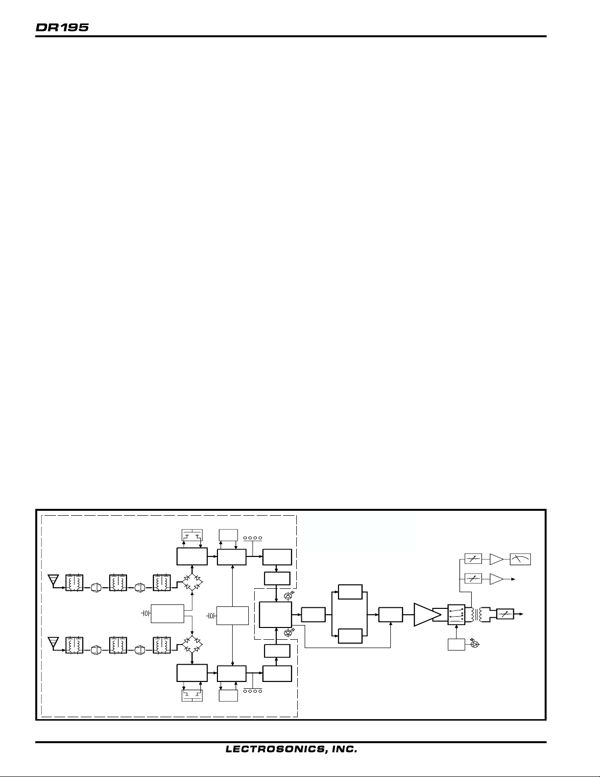
GENERAL TECHNICAL DESCRIPTION
The DR195 consists of two high performance, dual-conversion
receivers operating simultaneously. The audio outputs of the
receivers are blended in a ratio controlled by the compared
signal to noise ratios of the receivers. The RF section is
mounted on a separate circuit board, permitting frequency
changes by simply interchanging the RF section assembly.
The RF performance is extremely stable over a very wide
temperature range, making the DR195 perfectly suited to
mounting in studio equipment racks. The proprietary audio
processing includes a dual-band compandor and dynamic
noise filter for very low distortion and a superior signal to
noise ratio. The squelch system is operated by a separate pilot
tone and mutes the audio output directly at the output connector. The audio output is calibrated for exact level matching,
with both peak LED and average VU indicators.
MODULAR UHF/VHF RF SECTION
A unique modular design is employed to simplify frequency
changes. By simply interchanging the RF section module, the
frequency can easily be changed without test equipment or
soldering. All RF stages are contained in the removable RF
section. The output of the RF section is audio, so changes to a
new frequency, even from UHF to VHF, are simply a matter of
changing out the RF module. This modular design provides
the RF reliability of a fixed frequency design and the frequency flexibility of a switchable design.
As a side note, it is important to realize that frequency changes
“on the fly” cannot be made on any type of wireless system.
This is especially true in multi-channel applications where
changing the frequency of one system could produce all kinds
of new intermodulation problems with other systems operating
in the same location. In reality, frequency changes can only be
made on any wireless system during idle periods when the
systems are not in use. For example, if there is a problem with
a transmitter being used on stage that requires a frequency
change, the change cannot be made without interrupting the
program or waiting until there is time between shows.
SIX-POLE HELICAL RESONATOR FRONT-END
The DR195 utilizes dual six-pole helical resonator front-end
filtering, 3 pairs for each receiver. The helical resonators are
much larger than those typically used for wireless microphone
frequencies, producing an extremely high filtering “Q.” The
result is that the DR195 is not affected by high power signals
close to the carrier, and offers extremely high image rejection.
GaAs FET FRONT-END FILTER COUPLING
The DR195 utilizes ultra low noise GaAs FET amplifiers in
the front-end section to compensate for the required losses
between filter stages. The GaAs FET devices are extremely
quiet, especially at the higher frequencies in the UHF band.
DOUBLE BALANCED DIODE MIXERS
A double balanced diode mixer is used in the DR195 to
produce the 10.7 MHz IF signal. The mixer produces output
at only the sum and difference signals, with minimal spurious
signals. This mixer offers a very high overload threshold and
a high degree of isolation between ports.
8 POLE LINEAR PHASE FILTER
The 1st IF amplifier is a 4 stage amp with 2 poles of filtering
after each stage. The filters are high quality, low distortion,
constant group delay ceramic filters. This special type of filter
is needed to accommodate the wide deviation of the 195
system.
RF MODULE
HELICAL
GaAS
HELICAL
GaAS
FET
GaAS
FET
HELICAL
RESONATOR
XTAL
CONTROLLED
1ST
OSCILLATOR
HELICAL
RESONATOR
174-608
mHz
174-608
mHz
RESONATOR
HELICAL
RESONATOR
FET
GaAS
FET
RESONATOR
HELICAL
RESONATOR
Figure 1 - DR195 Block Diagram
6
8 POLE
LINEAR PH ASE
FILTER
IF
AMP
DIODE MIXER
HI-LEVEL
DIODE MIXER
IF
AMP
8 POLE
LINEAR PH ASE
FILTER
HI-LEVEL
455KHZ
BP
FILTER
2ND MIXER
&
IF AMP
XTAL
CONTROLLED
2ND
OSCILLATOR
2ND MIXER
&
IF AMP
455KHZ
BP
FILTER
RF LEVEL
LEDs
RF LEVEL
LEDs
COUNTING
DETECTOR
50 KHZ
LP FILTER
RATIO
COMBINER
&
OPTI-BLEND
50 KHZ
LP FILTER
COUNTING
DETECTOR
23 KHZ
LP
FILTER
2:1
EXPANDER
TREBLE
2:1
EXPANDER
BASS
VARIABLE
CUT-OFF
LP FILTER
AUDIO
AMPLIFIER
PILOT
TONE
MUTE
HEADROOM
ADJUST
OUTPUT
LEVEL
ADJUST
HEADPHONE
OUT
XLR
OUT
Page 7

Wireless Diversity Receiver
DIGITAL PULSE COUNTING DETECTOR
The DR195 receiver uses an advanced digital pulse detector to
demodulate the FM signal, rather than a conventional quadrature detector. The most common problem with quadrature
detectors is thermal drift, particularly those that operate at
higher frequencies like 10.7 MHz. The DR195 design
presents an elegantly simple, yet highly effective solution to
this age old problem.
The DR195 detector basically works like this: A stream of DC
pulses is generated at 455KHz. The pulse width is constant,
but the timing between pulses varies with the frequency shift
of the FM signal. The pulse stream is controlled by the FM
signal coming from the IF section which has been heavily
limited. The average voltage of the pulses within any given
time interval varies in direct proportion to the frequency
modulation of the radio signal, producing the audio signal.
This type of detector eliminates the traditional problems with
quadrature detectors and provides very low audio distortion,
high temperature stability and no thermal drift. The counting
detector also adds additional AM rejection, in addition to the
limiting in the IF section. The amplitude of the pulses is
constant, so level differences in the IF signal do not affect the
pulse.
RATIO COMBINING DIVERSITY WITH OPTI-BLEND
The audio outputs of the receivers are mixed together in a ratio
controlled by the RF level of the received signal.
2:1 EXPANDER (Dual–Band Compandor)
This circuit is the other half of the dual-band compandor in a
195 system. “Dual-band Companding” is a closed loop
system, that is, whatever is done in the transmitter must be
mirrored in the receiver. The transmiter compresses the audio
signal in two separate audio bands using two separate time
constants in order to avoid the inevitable trade-offs in a singleband compandor. The companion circuit in the receiver then
re-expands this compressed signal restoring the original
dynamic range and frequency characteristics of the signal.
The mixed audio signal leaves the Opti-Blend circuit and is
fed through a 23 kHz Low Pass Filter where all the high
frequency noise (including the 32 kHz pilot tone) is filtered
out. After the 23 kHz low pass filter, the signal is split into
two parts via a 1 kHz low pass filter and a 1 kHz high pass
filter. The separated signals are then processed in separate
channels of the NE575 2:1 Expander. Each channel of the 2:1
Expander is optimized for it's respective frequency band. The
two outputs of the 2:1 Expander are then summed in an op-
amp summer and sent to the Variable Cut-off Low Pass Filter
as one signal.
VARIABLE CUTOFF LOW PASS FILTER
After being processed in the 2:1 expander, the audio signal is
passed through a “dynamic noise reduction circuit”. The
cutoff frequency of this filter is varied automatically by
sampling the audio signal. The audio bandwidth is held only
to that point necessary to pass the highest frequency audio
signal present at the time. This results in a dramatic reduction
of “hiss” during pauses in voice or music content. During
passages with a large high frequency content, this filter gets
completely “out of the way” and passes the signal with no
decrease in high-frequency response.
PILOT TONE MUTE (SQUELCH)
The 195 system utilizes a separate ultrasonic tone modulation
of the basic carrier to operate the receiver squelch. In the
transmitter, a 32kHz tone is injected into the audio signal after
the microphone preamp, just after the compandor. The
supersonic pilot tone is filtered out of the audio signal immediately after the detector in the receiver so that it does not
influence the compandor or various gain stages.
The basic benefit of the pilot tone squelch system is that the
receiver will remain squelched (muted) until it receives the
pilot tone from the matching transmitter, even if a strong RF
signal is present on the carrier frequency of the system. Once
a pilot tone is received, the receiver will remain open during
all signal conditions. If the transmitter signal degrades to the
point where hiss and noise may become objectionable, the
Opti-Blend and Variable Cutoff Low Pass Filter will work to
reduce the unwanted noise to an unnoticeable level. Since the
pilot tone is still keeping the receiver open, as soon as the
transmitter signal returns to normal, the audio signal is
instantly available with no delays.
The mute circuit drives a relay which physically disconnects
the output amplifier from the output audio transformer. The
relay then connnects the transformer primary to ground to
prevent hum pickup in the transformer due to an open primary
winding. This provides complete muting of the audio and the
noise. The pilot tone function may be bypassed with a rear
panel push button. Once pushed, the pilot tone mute is
“latched” in a disabled condition until the receiver is powered
off then back on. When the pilot tone is disabled, there is still
a “squelching” function provided by the Opti-Blend and
Variable Cutoff Low Pass Filter. These circuits can provide
approximately 50 dB of muting during weak or no signal
conditions when the pilot tone is disabled.
Rio Rancho, NM – USA
7
Page 8

FRONT PANEL CONTROLS AND FUNCTIONS
AUDIO OUTPUT LEVEL
A high quality VU meter is used to monitor the audio ouput level, providing an accurate indication of the average audio output
level. The VU meter sensitivity is adjusted with a rear panel control to compensate for the difference in transient response rise
time between the VU meter and the LED strip below the meter. Depending upon the dynamic characteristics of the audio
source, it may be necessary to adjust for headroom in the VU meter.
If the signal peaks exceed full modulation, distortion or audible compression could occur. In the past, it was common practice
with other designs to adjust the VU meter sensitivity to allow headroom, compensating for the slow rise time of the VU meter.
These older designs did not have peak reading indicators, therefore, by the time the VU meter indicated 0dB, the actual peak
level was far above full modulation. The DR195 output and VU meter headroom controls provide an absolute level reference
and calibrated sensitivity adjustments.
TRANSMITTER AUDIO LEVEL
The modulation (audio level) of the incoming signal is indicated by a fast responding LED strip. The strip is calibrated in 6dB
steps over an expanded scale (54dB) which provides an extremely accurate visual “picture” of the signal dynamics, even at a
distance away from the receiver. Audio signal peaks easily exceed the response time of VU meters, however, the LED strip is
fast enough to track even brief transients. The combination of the LED strip and the conventional VU meter provides a complete and accurate visual monitoring of signal levels and dynamic range.
RF LEVEL INDICATORS
Two separate LED strips are provided to indicate the level of the incoming RF signals. The LED strips are calibrated to provide
accurate indications from 1uV to 1mV. The LEDs are highly visible from a distance, making antenna set up more accurate. The
dual LED strips are especially useful in “trouble-shooting” difficult antenna installations.
OPTI-BLEND LEDs
The DR195 receiver operates with a method of audio ratio blending of two audio outputs. RF level in each receiver is compared
and the audio signals from the two receivers are mixed together in a ratio that favors the quieter receiver. As this blending action
occurs, the brightness of the two OPTI-BLEND LEDs will vary. The brighter the LED, the more audio is being mixed in from
that receiver.
50
25
105
RF LEVEL
500 250 100
CH A
OPTI
BLEND
CH B
LECTROSONICS
20
1uV 2 uV 1mV
12
3
5
7
10
20
0
60
40
AUDIO OUTPUT LEVEL
0
1
80
100
2
3
PILOT
DIVERSITY
A B
TRANSMITTER AUDIO LEVEL dB
Figure 2 - DR195 Front Panel
8
-6
-12 -18 -24 -30 -36 -42 -48
LIM 0
MODE MONITOR POWER
Page 9

Wireless Diversity Receiver
PILOT LED
The audio output muting (squelch) function of the DR195 is controlled by a 33kHz tone modulation of the RF carrier. The audio
output is muted until this tone is present. As soon as the tone is received, this LED is turned on to indicate the audio output is
enabled.
The pilot tone function can be defeated by pressing a switch on the rear panel. The PILOT LED, however, operates the same
regardless of whether or not the defeat switch is pressed. The PILOT LED strictly indicates the presence of the pilot tone carrier
from the transmitter.
DIVERSITY MODE
This switch is set to the DIVERSITY position for normal operation. For trouble-shooting or when the receiver is used with a
single antenna, the switch can be set to select a single antenna only.
MONITOR
This is an audio output to drive a wide variety of different types of headphones. It is also useable as a secondary audio output to
drive recorders or external audio devices.
POWER
Pressing the upper half of the rocker switch applies power to the receiver. At turn on, there are various relays and delays built
into the receiver to allow various stages to stabilize before the audio output is activated. This will prevent an audio “thump”
when powering up the receiver and/or the transmitter.
Rio Rancho, NM – USA
9
Page 10

REAR PANEL CONTROLS AND FUNCTIONS
VU METER HEADROOM
Since VU meters are too slow to respond to brief transients in audio signals, they do not indicate “peaks” in the audio signal,
however, they do indicate the average levels of the audio signal in the 20dB range below maximum level. A calibrated sensitivity control is provided on the DR195 rear panel to allow the VU meter sensitivity to be increased so that it will more closely
track the modulation level LED strip with different kinds of program material.
AUDIO OUTPUT
A calibrated control on the rear panel adjusts the output level in 5 dB steps, referenced in dBu. This control knob adjusts the
absolute output level at the XLR connector when the VU meter indicates “0” so that an exact level can be reliably achieved. The
5dB increment on the output level control matches the 5dB increment on the VU meter headroom control so it is easy to determine the true output level. For example, with the VU meter headroom control set for 10dB, the actual audio output level will be
*10dB lower than the VU meter indicates. Setting the output level control 10dB higher will compensate for the additional
sensitivity of the VU meter. The Audio Output level control is located after the output transformer. This allows the signal to
noise ratio to remain constant regardless of the setting of the control. As the audio level is reduced, the noise is also reduced
maintaining the same ratio.
PHASE REV
This locking toggle switch reverses the polarity of the audio output signal.
AC POWER SUPPLIES
The DR195 can be powered from conventional 110 or 220 Volt AC supplies via an internationally approved connector. A
standard grounded socket, fuseholder and voltage selector switch are combined into a single assembly. The fuseholder also
contains a spare fuse. To remove the fuseholder, simply pry it out with a screwdriver or similar tool (it pulls straight outward
from the assembly). To select the operating voltage, disconnect the AC power and then turn the voltage selector (located to the
left of the fuse) using a flatblade screwdriver or other similar tool so that the desired voltage is lined up with the mark at the top.
LECTROSONICS
RIO RANCHO, NM (800) 821-1121 MAD E IN USA
1
0
1
2
2
0
RECEIVER
ANTENNA B
BUSS: GDC 315mA (160mA) LITTLEFUSE: T 315mA (160mA) (218)
Figure 3 - DR195 Rear Panel
10
- -
EXTERNAL POWER
12-18V DC (NON POLAR)
CONTACT CLOSURE
NORMALLY OPEN
-
-
(PINS 1,4)
(PINS 2,3)
PILOT
TONE
REV BYPASS
dB
10
15
5
1
4
3
2
0
VU METER
HEADROOM
20
dBu
0
-5
-25
-30
+5
-35
-10 +10
-15
-20
AUDIO OUTPUT
+15
-40
ANTENNA A PHASE
2
1
3
Page 11

Wireless Diversity Receiver
EXTERNAL POWER JACK
The DR195 can be powered from external 12 to 18 Volt DC sources via the four pin XLR jack. The jack is non-polarized
between pins 1 and 4. Internal relays correct the polarity automatically if reverse polarity is connected. By using relays to
correct the power supply polarity, there is no voltage drop, as would occur in a diode bridge circuit. The relays and power
supply stage are fully protected by automatic reset poly fuses. The ground side of the power supply is protected with a self
resetting poly fuse in case the DR195 is connected to a positive ground device through the audio cabling. The poly fuse will
trip to protect the receiver and the offending ground path can then be removed.
CONTACT CLOSURE
This switch is used to activate an external device, such as a tape recorder or an external relay. The switch is keyed to the pilot
tone squelch function of the receiver. When the squelch opens, a contact closure (or opening) is activated at this connector.
Pins 2 and 3 of the four pin XLR connector can be configured for “normally open” or “normally closed” operation. The unit is
shipped from the factory in the “normally open” position, which means that there is a short between pins 2 and 3 of the four pin
XLR when there is a pilot tone present.
The PILOT TONE BYPASS switch defeats the action of the relay. With the pilot tone bypassed, the relay will remain shorted
until the power to the receiver is turned off, regardless of the presence of a pilot tone carrier. To return to pilot tone use, switch
the receiver power completely off then back on.
PILOT TONE BYPASS
This switch defeats the audio output muting and triggering action of the pilot tone. When the pilot tone is bypassed, the OptiBlend and the Variable Cutoff Low Pass Filter will still provide a squelching action during weak signal conditions. These
circuits will provide approximately 50 dB of muting when the pilot tone is bypasssed.
ANTENNA JACKS
These are standard 50 Ohm BNC terminals for the RF input to the receiver.
Rio Rancho, NM – USA
11
Page 12

ANTENNA USE AND PLACEMENT
There are two remote antenna assemblies included with this receiver. Position the antennas at least three or four feet apart at
VHF frequencies and so that they are not within 3 or 4 feet of large metal surfaces. If this is not possible, try to position the
antennas so that they are as far away from the metal surface as is practical. It is also good to position the receiver so that there is
a direct “line of sight” between the transmitter and the receiver antenna. In situations where the operating range is less than
about 50 feet, the antenna positioning is much less critical. The antennas can also be configured with one whip mounted directly
onto the rear panel of the DR195 receiver, and the other one mounted remotely.
A wireless transmitter sends a radio signal out in all directions. This signal will often bounce off nearby walls, ceilings, etc. and
a strong reflection can arrive at the receiver antenna along with the direct signal. If the direct and reflected signals are out of
phase with each other a cancellation may occur. The result would be a “drop-out.” A drop-out sounds like either audible noise
(hiss), or in severe cases, may result in a complete loss of the carrier and the sound when the transmitter is positioned in certain
locations in the room. A drop-out normally sounds like “hiss” or a “swishing” sound. Moving the transmitter even a few inches
will change the sound of the hum or hiss, or eliminate it. A drop-out situation may be either better or worse as the crowd fills
and/or leaves the room, or when the transmitter or receiver is operated in a different location.
The DR195 receiver offers a sophisticated diversity design which overcomes drop-out problems in almost any imaginable
situation. In the event, however, that you do encounter a dropout problem, first try moving the antenna at least 3 or 4 feet from
where it was. This may alleviate the drop-out problem on that antenna. If drop-outs are still a problem, try moving the antenna
to an entirely different location in the room or moving the antennas in closer to the transmitter location. By observing the OPTIBLEND LEDs on the front panel, you can determine which antenna is suffering weak signals.
Lectrosonics transmitters radiate power very efficiently, and the receivers are very sensitive. This reduces drop-outs to an
insignificant level. If, however, you do encounter drop-outs frequently, call the factory or consult your dealer. There is probably
a simple solution.
REFLECTIVE SURFACE
I
N
D
I
R
E
C
T
S
I
G
N
A
L
L
A
N
G
I
S
T
C
E
R
I
D
TRANSMITTER
PHASE
CANCELLATION
Figure 4 - Drop-outs
12
DIRECT SIGNAL
RECEIVER
INDIRECT SIGNAL
MULTI-PATH DROPOUT
Page 13

Wireless Diversity Receiver
INSTALLATION AND OPERATING INSTRUCTIONS
1) If operating the unit from AC power, determine the line voltage to be used and set the Line Voltage Selector on the rear panel
to match. The units are shipped with the proper size fuse for use with 120V systems (315mA). If the unit will be used in a
220V environment, change the fuse to a 160mA of the same type. See the section "DR195 Replacement Parts and Accessories" for manufacturer part numbers of the correct type and value for 110 and 220 Volt supplies.
2) Locate a suitable operating location where the DR195 will not be subjected to extreme temperature variations and possible
bumps and drops. Try to route all wiring so it will not cross walkways or isles.
3) Connect the power. For 120V AC operation, connect the power cord to the AC input jack on the rear panel and plug the other
end into a suitable electrical outlet. If 12 to 18 Volts DC operation is desired, a power cord will need to be fabricated. Use a
standard A4M XLR connector for the DR195 end and wire the 12 to 18 VDC to pins 1 and 4. The DR195 will operate with
either polarity. Make the length of the DC cable long enough to suit your installation and prepare and connect the source end
of the cable.
4) Attach the antenna cables to the BNC jacks on the rear of the DR195 and place the antennas. Best performance will be
obtained if the antennas are placed at least 3 feet from each other. Try to mount them as high as possible with a direct line of
sight path to the transmitter.
5) Set the Audio Output level control to minimum (CCW) and connect the Audio Output XLR jack to the mixer input. Pins 2
and 3 of the XLR jack are HI and LO and can be reversed with the Phase switch, pin 1 is common.
6) Preset the following controls: MODE (front panel) to DIVERSITY
7) Turn the unit on with the front panel Power switch and check to see that the red Pilot LED is off (be sure the transmitter is
turned off.) The VU meter will be lit only when the unit is operated from 120 VAC.
MONITOR (front panel) to minimum (CCW)
PHASE (rear panel) to UP
VU METER HEADROOM (rear panel) to 0
AUDIO OUTPUT (rear panel) to -40 (full CCW)
8) Turn on the transmitter and adjust the transmitter gain. THIS IS PERHAPS THE MOST IMPORTANT STEP IN THE SET
UP PROCEDURE. Adjust the transmitter so that voice peaks will light the 0 LED on the DR195 front panel Transmitter
Audio Level dB strip. The red LIM LED may flash occasionally. This is normal but it should not happen very often. See
your transmitter manual (Operating Instructions section) for specific directions on how to adjust the gain of your particular
transmitter.
9) After adjusting the transmitter gain, set the rear panel Audio Output level control to the desired level. The -40 setting is
approximately equal to 10mV, the 0 position will give 0.775VRMS, and the +15 setting will allow up to 4.4 VRMS. This
setting will depend on the requirements of your system.
10) Operate the system and re-adjust the receiver output level as required for your equipment. The input levels on different
VCR’s and PA equipment vary, which may require that you set the OUTPUT ATTENUATOR control in an intermediate
position. Try different settings and listen to the results. If the output of the receiver is too high, you may hear distortion or a
loss of the natural dynamics of the audio signal. If the output is too low, you may hear steady noise (hiss) along with the
audio.
11) Once the transmitter and Audio Output level has been set, you may adjust the VU Meter Headroom on the rear panel so the
analog VU meter will swing to 0 on normal audio peaks. The Headroom control is calibrated 0 to 20 dB in 5 dB steps so it is
always possible to know what the VU meter is actually measuring. For instance, if the VU meter is indicating 0 with a steady
state audio tone and the Headroom control is set to "5", the audio output is -5 dBu. The Headroom switch actually adjusts the
sensitivity of the VU meter by a calibrated amount. Without it, the VU meter would not deflect at all if the Audio Output was
set to a low setting such as –30.
Rio Rancho, NM – USA
13
Page 14

TROUBLESHOOTING
POWER SUPPLY AND FUSE
VU meter lamp and LEDs not lit or dimly lit — When the DR195 is powered from an external DC supply, the VU
meter lamp stays out and the LEDs are dimmed to conserve battery life.
AC power cord disconnected.
External power supply disconnected or inadequate.
Main power supply fuse blown.
For 110 Volt operation: 315 mA, 250 Volt
Buss GDC-315 or Littlefuse 218.315 (Lectrosonics part #22090)
For 220 Volt operation: 160mA, 250 Volt
Buss GDC-160 or Littlefuse 218.160 (Lectrosonics part #22091)
Rear panel voltage selector incorrectly set.
PILOT TONE SQUELCH
The PILOT indicator lamp on the front panel lights up to indicate that the audio has been turned on at the transmitter, and that
the audio output on the receiver is enabled. When the lamp is on, the audio is on. When the lamp is off, the audio is muted.
PILOT lamp on, but no sound
Audio output cable bad or disconnected. Try monitoring at the headphone output on the front panel. The headphone output signal is taken just ahead of the output transformer.
AUDIO OUTPUT level set too low.
PILOT lamp off, but sound still comes through
PILOT TONE BYPASS switch may have been pressed. Turn DR195 power off and then back on again to reset the
audio output relays.
PILOT lamp does not come on when transmitter audio switch is turned on
It takes several seconds for the relay to actuate the PILOT lamp. Turn the transmitter power and audio switches on
and wait 5 to 10 seconds for the lamp to come on.
ANTENNAS AND RF SIGNAL STRENGTH
RF LEVEL is weak on one (or both) channels
Antenna is disconnected or there is a bad connection
Antenna may need to be moved or re-oriented
Improper length of antenna, or wrong antenna. UHF whip antennas should be about 5 to 6 inches long. VHF whip
antennas: should be about 14 to 20 inches long.
One OPTI BLEND LED does not come on or is dimly lit
DIVERSITY switch is set to one or the other channels. Needs to be in the center position for normal operation.
14
Reverse the antennas on the rear panel inputs. If the opposite OPTI BLEND LED now indicates the same problem,
there may be an antenna or cabling problem. Try re-positioning the antenna(s).
Page 15

AUDIO SIGNAL QUALITY
Poor signal to noise ratio
Transmitter gain set too low
Noise may not be in wireless system. Mute the audio signal at the transmitter and see if noise remains. If the noise
remains, then turn the power off at the transmitter and see if it remains. If the noise is still present, then the problem
is not in the transmitter.
If noise is still present when the transmitter is turned off, try lowering the audio output level on the DR195 rear
panel and see if the noise lowers correspondingly. If the noise remains, the problem is not in the receiver.
Wireless Diversity Receiver
Receiver output does not match the input of the device it is feeding. Try increasing the output level of the DR195
and lowering the input gain on the device the DR195 is feeding.
Distortion
Transmitter input gain too high. Check and/or re-adjust input gain on transmitter according to the LEDs on the
transmitter and then verify the setting with the transmitter audio level LED strip on the DR195 front panel.
Audio output level too high for the device the DR195 is feeding.
Compressed dynamic range
VU METERING AND OUTPUT LEVEL
The TRANSMITTER AUDIO LEVEL LED strip provides an expanded scale range and virtually an instantaneous response to
brief transients in the signal. The VU meter range is much more limited, and slower responding to brief transients.
VU meter barely moves, even when the AUDIO LEVEL LED strip shows full modulation
Depending upon the nature of the dynamics in the audio signal passing through the system, you may need to
increase the sensitivity on the VU meter. Adjust the VU meter sensitivity with the rear panel VU METER HEADROOM control on the rear panel so that the LED strip and VU meter appear to track signal peaks about the same.
VU meter indicates a higher level than the AUDIO LEVEL LED strip.
The VU METER HEADROOM control may be set too high for the dynamics of the audio signal.
NOTE: When adjusting the VU METER HEADROOM control to increase the VU meter readings, it may be desirable to also
adjust the AUDIO OUTPUT control to compensate for the added sensitivity of the VU meter. Both controls are calibrated in 5
dB steps. Increase the AUDIO OUTPUT by the same amount as is set on the VU METER HEADROOM control to insure that
the desired output level will be present at 0 on the VU meter.
DR195 REPLACEMENT PARTS and ACCESSORIES
Part No. Description
A-185 Coax Remote, coaxial folded dipole VHF antenna; BNC connector
A-185-BNC Telescoping 1/4 wave VHF/UHF whip; BNC connector.
A-200 Remote dipole UHF/VHF antenna with aluminum mounting block; supplied with one
built-in telescoping whip and one detachable telescoping whip. Operates on VHF or UHF
frequencies.
A-9775 Coaxial extension cable for A-200 dipole antenna; BNC male/male connectors, 10 ft,
RG-58 cable.
21475 Replacement power cord
22090 Replacement fuse, GDC, 315ma, 250V
22091 Replacement fuse, GDC, 160mA, 250V
Rio Rancho, NM – USA
15
Page 16

SPECIFICATIONS AND FEATURES
Receiver
Operating Frequencies: 470 to 608 MHz, crystal controlled
Receiver Type: Dual conversion, superheterodyne
Frequency Stability: ±0.002 %
Front end selectivity: >70 dB at ±4 MHz
IF Selectivity: >90 dB at ±300 kHz (10.7 IF)
IF Frequency: 10.7 MHz (1st IF); 455 kHz (2nd IF)
IF bandwidth: 150 kHz at ½ power points
Sensitivity
20 dB Sinad: 0.56 uV (-113 dBm), A weighted
60 dB Quieting: 1.0 uV (-112 dBm), A weighted
Squelch quieting: Greater than 125 dB
AM rejection: Greater than 60 dB, 2uV to 1 Volt
(Undetectable after processing)
Modulation acceptance: ±75 kHz
Image and spurious
rejection: > 120 dB
Third order intercept: –10 dBm
Diversity technique: Ratio diversity. Dual simultaneous
receivers with dynamic audio
combining (Opti-blend).
FM Detector: Digital Pulse Counting Detector
Antenna inputs: Dual BNC female;
50 Ohm impedance
Audio outputs
Rear Panel XLR: 600 Ohm Balanced, transformer
isolated, adjustable from 10 mV to
4.4 Volts RMS in 12 steps, at 60
kHz deviation
Monitor out: Front panel ¼” Phone jack,
adjustable from 0 to 600 mV RMS
into 8 Ohms at 60 kHz deviation
Front Panel Controls and
Indicators: Power on/off switch and LED;
Dual 10 segment RF signal level
display; 10 segment transmitter
audio level display; diversity
operation selector switch; OptiBlend operation LEDs; Pilot tone
indicator; Monitor output jack
Rear Panel Controls and
features: Antenna A and Antenna B BNC
Power Options: 120/240 VAC, 50/60 Hz, 10 Watts
Weight: 8 lbs, 11 ozs
Dimensions: 8 ½” wide x 3 ½” high x 13" deep
System (DR195 receiver with T195 transmitter)
Audio Processor: Dual–band compandor with variable
Total Harmonic
Distortion
1 kHz: <0.45%
30 Hz to 20 kHz: < 1% (30 kHz deviation)
and level control;
connectors; Pilot tone bypass
switch; Audio phase reversal
switch; VU meter headroom
control; XLR audio output jack
and 12-step audio attenuator;
External 12VDC input and
contact closure output jack; 120/
240 VAC input jack with integral
voltage selector switch and fuse.
12V DC, 7 Watts (560 ma)
( With handles and power cord)
cut-off frequency low-pass filter
16
Signal/Noise ratio: 109 dB, full quieting, A weighted
60 dB, A-weighted, at .63 uV
(-111 dBm) signal input
Frequency Response: ±1 dB, 30 Hz to 21 kHz,
400 Hz reference, 30 kHz deviation
Page 17

Wireless Diversity Receiver
SERVICE AND REPAIR
If your system malfunctions, you should attempt to correct or isolate the trouble before concluding that the equipment needs
repair. Make sure you have followed the setup procedure and operating instructions. Check out the inter-connecting cords and
then go through the TROUBLE SHOOTING section in the manual
We strongly recommend that you do not try to repair the equipment yourself and do not have the local repair shop attempt
anything other than the simplest repair. If the repair is more complicated than a broken wire or loose connection, send the unit
to the factory for repair and service. Don’t attempt to adjust any controls inside the units. Once set at the factory, the various
controls and trimmers do not drift with age or vibration and never require readjustment. There are no adjustments inside that
will make a malfunctioning unit start working.
LECTROSONICS service department is equipped and staffed to quickly repair your equipment. In-warranty repairs are made at
no charge in accordance with the terms of the warranty. Out of warranty repairs are charged at a modest flat rate plus parts and
shipping. Since it takes almost as much time and effort to determine what is wrong as it does to make the repair, there is a
charge for an exact quotation. We will be happy to quote approximate charges by phone for out of warranty repairs.
RETURNING UNITS FOR REPAIR
You will save yourself time and trouble if you will follow the steps below:
A. DO NOT return equipment to the factory for repair without first contacting us by letter or by phone. We need to know the
nature of the problem, the model number and the serial number of the equipment. We also need a phone number where you
can be reached 8 am to 4 pm (Mountain Standard Time).
B. After receiving your request, we will issue you a return authorization number (R.A.). This number will help speed your
repair through our receiving and repair departments. The return authorization number must be clearly shown on the outside
of the shipping container.
C. Pack the equipment carefully and ship to us, shipping costs prepaid. If necessary, we can provide you with the proper
packing materials. UPS is usually the best way to ship the units. Heavy units should be “double-boxed” for safe transport.
D. We also strongly recommend that you insure the equipment, since we cannot be responsible for loss of or damage to equip-
ment that you ship. Of course, we insure the equipment when we ship it back to you.
Mailing address:
Lectrosonics, Inc.
PO Box 15900
Rio Rancho, NM 87174
USA
Shipping address:
Lectrosonics, Inc.
581 Laser Rd.
Rio Rancho, NM 87124
USA
Phones:
505-892-4501
800-821-1121
505-892-6243 Fax
We b: http://www.lectrosonics.com email: sales@lectrosonics.com
Rio Rancho, NM – USA
17
Page 18

LIMITED ONE YEAR WARRANTY
The equipment is warranted for one year from date of purchase against defects in materials
or workmanship provided it was purchased from an authorized dealer. This warranty does
not cover equipment which has been abused or damaged by careless handling or shipping.
This warranty does not apply to used or demonstrator equipment.
Should any defect develop, we will, at our option, repair or replace any defective parts
without charge for either parts or labor. If we cannot correct the defect in your equipment,
we will replace it at no charge with a similar new item. We will pay for the cost of returning
your merchandise to you.
This warranty applies only to items returned to us, shipping costs prepaid, within one year
from the date of purchase.
This warranty gives you specific legal rights. You may have additional legal rights which
vary from state to state.
LECTROSONICS, INC.
581 LASER ROAD
RIO RANCHO, NM 87124 USA
18
July 6, 1999
 Loading...