

Page 1

UCR 210 D
DIVERSITY UHF RECEIVER
OPERATING INSTRUCTIONS
and trouble-shooting guide
LECTROSONICS, INC.
WWW.LECTROSONICS.COM
Rio Rancho, NM
Page 2

TABLE OF CONTENTS
GENERAL TECHNICAL DESCRIPTION .............................................................. 3
FRONT PANEL CONTROLS AND FUNCTIONS .................................................. 6
REAR PANEL CONTROLS AND FUNCTIONS .................................................... 7
ANTENNA USE AND PLACEMENT ..................................................................... 8
INSTALLATION AND OPERATING INSTRUCTIONS .......................................... 9
UCR210D REPLACEMENT PARTS and ACCESSORIES ................................... 9
FREQUENCY BLOCKS AND RANGES ............................................................. 10
TROUBLESHOOTING ........................................................................................ 11
SPECIFICATIONS AND FEATURES .................................................................. 12
SERVICE AND REPAIR ...................................................................................... 13
RETURNING UNITS FOR REPAIR .................................................................... 13
WARRANTY .......................................................................................... Back cover
2
Page 3
UHF Wireless Diversity Receiver
T
GENERAL TECHNICAL DESCRIPTION
The UCR210D is a portable, high performance, triple-conversion,
frequency synthesized, UHF receiver. The RF performance is
extremely stable over a very wide temperature range, making the
UCR210D perfectly suited to the rough environmental conditions
found in the field. The proprietary audio processing includes a
dual-band compandor for very low distortion and a superior signal
to noise ratio. The Smart Squelch system is operated by a separate
pilot tone and mutes the audio output directly at the output connector.
DIVERSITY RECEPTION
The antenna phase SMART switching diversity technique was
chosen in order to keep the receiver compact enough for camera
mounted or shoulder bag applications. This diversity reception
technique effectively minimizes dropouts in short range situations
where multi-path reflections can cause serious problems. The
optimum diversity reception is realized with the diversity antenna
placed away from the receiver, however, dropouts are significantly
reduced even if the two antennas are mounted directly on the
receiver.
RF SECTION
The problem posed to the design staff was to retain the RF reliability of the Lectrosonics’ fixed frequency designs but add the
flexibility of a frequency agile design. The universal (and poor)
way to build frequency agile systems is to design a wide open front
end that will pass any frequency within the tuning range of the
system. This leads to very poor RF performance with lots of
interference, driving the user to switch frequencies in an attempt to
sidestep the interference. This makes frequency agile receivers a
self fulfilling system; you have to use the frequency agility to get
away from the problems caused by the frequency agile design
compromises.
The problem of frequency agility is further compounded when you
realize that frequency changes “on the fly” cannot be made on any
type of wireless system. For example, if there is suddenly an
interference problem with a system in use, on stage for instance, a
frequency change cannot be made without interrupting the program. Basically, the show must go on. In multi-channel
applications, changing the frequency of one system will usually
produce all kinds of new intermodulation problems with the other
systems operating in the same location. Frequency agility is not the
universal panacea for interference problems. It is only another tool
and a limited tool at that. The first line of defense must be the
system’s basic immunity to interference. That required a new look
at frequency agile receiver design.
FREQUENCY TRACKING FRONT-END
Our solution to the wide open front end problem was to design a
selective front end that can be tuned to the frequency in use. Since
we wanted this front end to be equivalent to our fixed frequency
front ends, this was a daunting task. Lectrosonics has always used
front ends with more sections and much more selectivity than any
other wireless manufacturer. The final design consists of a total of
4 transmission line resonators with variable capacitance applied to
each resonator by the hexadecimal switches.
This sophistication produces a front end that is as selective as fixed
frequency designs. The next step to improve the front end is to use
good old fashioned “brute force.”
HIGH CURRENT LOW NOISE AMPLIFIERS
The gain stage in the front end uses a rather special transistor in a
feedback regulated high current circuit that combines three parameters that are generally at odds with one another. These are: low
noise, low gain and relatively high power. It is easy to understand
the advantages of low noise and high power capability but why is
low gain desirable? The answer is that in a receiver, low gain
allows the front end to handle stronger RF signals without output
overload, which is “increased headroom,” so to speak. The result
of a design that takes all three of these parameters into consideration at once, is a low noise RF amplifier with a sensitivity rating
equal or better than the best conventional design with a hundred
times less susceptibility to intermodulation interference.
Combining the high power gain stage with the tracking front end
produces a receiver that is unusually immune to single and multiple
interfering signals close to the operating frequency and in addition
strongly rejects signals that are much farther away.
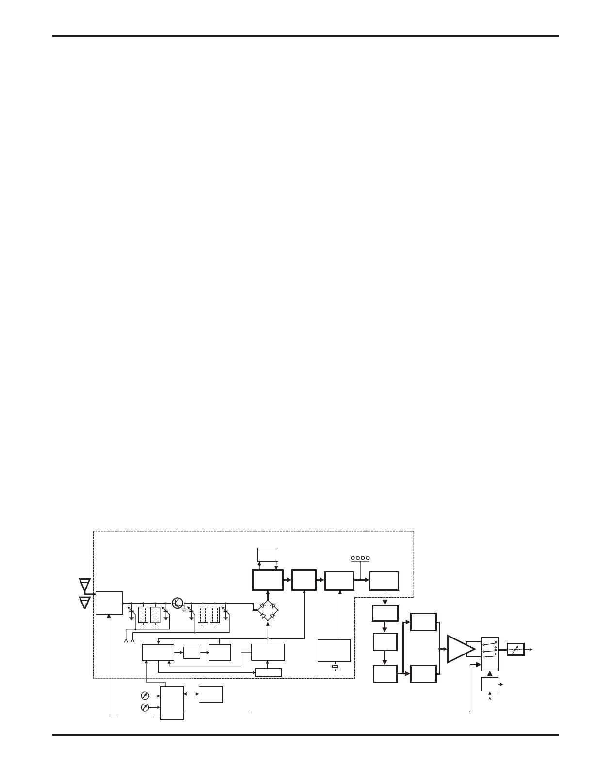
RF MODULE
ANTENNA
SWITCHING
uP
uP
FREQ
SWITCHES
Smart Diversity
FILTER
SYNTHESIZER
UCR210D
3RD MIXER
AND
IF AMP
XTAL
3rd
OSCILLATOR
RF LEVEL
LEDs
COUNTING
DETECTOR
50KHz
LP FILTER
23 KHZ
LP
FILTER
VARIABLE
CUT-OFF
LP FILTER
EXPANDER
EXPANDER
SAW
FILTER
HI-LEVEL
DIODE MIXER
2ND
MIXER
10.7 MHZ
CONTROLLED
71 MHz
IF AMP
AMP
FILTER
1ST
LOCAL
OSCILLATOR
FILTER
2
E PROM
2nd
VCO
Smart Squelch
FILTER
uP
Rio Rancho, NM – USA
BLOCK DIAGRAM
2:1
TREBLE
AUDIO
AMP
2:1
BASS
PILOT
TONE
MUTE
uP
OUTPUT
LEVEL
ADJUST
TO DATA
DISPLAY
XLR
OU
3
Page 4

DOUBLE BALANCED DIODE MIXERS
In all wireless receivers, a mixer is used to convert the carrier
frequency to the IF frequency where most of the filtering and gain
in the receiver takes place. After doing all the right things in the
front end, it would be a shame to waste the performance with a
second rate mixer. In other designs that is exactly what happens
since mediocre mixers cause more intermodulation problems than
mediocre front ends. The only solution was a high power, double
balanced diode mixer driven by a local oscillator with more output
power than most wireless transmitters (50 mW). The mixer in the
UCR210D produces output at only the sum and difference signals,
with minimal spurious signals. This mixer offers a very high
overload threshold and a high degree of isolation between ports.
The IF output of this mixer is at 71 MHz which is unusually high
for a wireless receiver. This high frequency was chosen to increase
the image rejection in the front end to as high or a higher level than
our fixed frequency designs. The mixer is followed by high current, low noise amplifiers and SAW filters to preserve the superior
RF performance.
SURFACE ACOUSTIC WAVE FILTER
The UCR210D is unique in that it uses a state of the art SAW filter
in the IF section. The SAW filter is the only filter that can combine
sharp skirts, constant group delay, and wide bandwidth in one filter.
Though expensive, this special type of filter allows us to follow the
basic receiver rule of doing the primary filtering as early as possible, at as high a frequency as possible and before high gain is
applied to the signal. Since these filters are made of quartz, they
are very temperature stable. Conventional LC filters at these
frequencies don’t begin to perform as well and in addition would
drift unacceptably in the elevated temperatures of an equipment
rack. After following the rule in a rigorous way, and due to the
sharp filtering action of the SAW filters, the 71MHz signal is
converted to 10.7Mhz and then to the low frequency of 300 kHz.
Lots of gain is then applied in a conventional IC and the signal is
then converted to audio. 300 kHz is very unconventional for a
second IF in a wide deviation (±50 kHz) system. We chose to use
300 kHz to obtain an outstanding AM rejection figure over a very
wide range of signal strengths and to produce an excellent noise
improvement at low signal strengths (capture ratio). To use an IF at
300 kHz requires an unusual circuit to convert the IF to audio.
DIGITAL PULSE COUNTING DETECTOR
The UCR210D receiver uses an advanced digital pulse detector to
demodulate the FM signal, rather than a conventional quadrature
detector. The common problem with quadrature detectors is thermal drift, particularly those that operate at higher frequencies like
10.7 MHz. Though the quadrature detectors may work well at
room temperature, if they are not carefully compensated, they will
produce amplitude changes and audio distortion in the elevated
temperatures of an equipment rack. Some manufacturers try to get
around the problem by tuning their systems at higher temperatures
after they’ve been on for some time. This just means that for the
first hours in a cool room the receiver is well out of specification or
after a few hours in a hot rack.
The UCR210D design presents an elegantly simple, yet highly
effective solution to this age old problem. The UCR210D detector
basically works like this: A stream of precision pulses is generated
at 300kHz locked to the FM signal coming from the 300 kHz IF
section. The pulse width is constant, but the timing between pulses
varies with the frequency shift of the FM signal. The integrated
voltage of the pulses within any given time interval varies in direct
proportion to the frequency modulation of the radio signal. Another way of describing it is that as the FM modulation increases
the frequency, the circuit produces more pulses and as the modulation decreases the frequency, the circuit produces fewer pulses.
More pulses produces a higher voltage and fewer pulses a lower
voltage. The resultant varying voltage is the audio signal.
This type of detector eliminates the traditional problems with
quadrature detectors and provides very low audio distortion, high
temperature stability and stable audio level. The counting detector
also adds additional AM rejection, in addition to the limiting in the
IF section. The amplitude of the pulses is constant, so level
differences in the IF signal do not affect the pulse.
TRI MODE DYNAMIC FILTER
The audio signal is passed through a “dynamic noise reduction
circuit”. The cutoff frequency of this filter is varied automatically
by measuring the amplitude and frequency of the audio signal and
the quality of the RF signal. The audio bandwidth is held only to
that point necessary to pass the highest frequency audio signal
present at the time. If the RF level is weak, then the filter becomes
more aggressive. This results in a dramatic reduction of “hiss” at
all times. During passages with a high frequency content, this filter
gets completely “out of the way” and passes the signal with no
decrease in high-frequency response. Keep in mind that if hiss is
added to a signal, there is a psycho acoustic effect that makes the
sound seem brighter. The other side of this is that if hiss is removed
from a signal it will sound duller. Basically the ear’s detection
apparatus is pre-sensitized to high frequency sounds by small
amounts of high frequency hiss. Consider this effect when making
a judgment about the sound quality of various wireless systems and
this particular filter. We have satisfied ourselves through elaborate
tests that this filter is totally transparent.
PILOT TONE MUTE
The UCR210D uses a pilot tone muting technique in order to
protect against the reception of stray signals. The Lectrosonics
transmitter adds an inaudible signal, known as the pilot tone, to the
transmitted signal. The receiver detects (and removes) the pilot
tone, and is thus able to identify the desired signal and mute all
others.
When the receiver is powered up, receive audio is muted unless a
proper pilot tone is detected. The pilot tone must be present for
approximately one second before the signal is accepted.
If the PILOT TONE BYPASS button is pressed, received audio
remains unmuted regardless of the presence or absence of a pilot
tone. This position is useful for locating a clear frequency, since
any potential interference may be heard. It may also be used in
situations where squelching behavior is undesirable. The “PILOT
TONE BYPASS” disables the squelch, as described below.
SMART SQUELCH
The UCR210D employs a sophisticated squelching system in an
attempt to deliver the cleanest possible audio during marginal
conditions of reception. Any squelching system faces inevitable
trade-offs: squelch too much and valuable audio information may
be lost, squelch too little and excessive noise may be heard; re-
4
Page 5

spond too rapidly and the audio sounds “choppy”, respond too
sluggishly and syllables or entire words are cut off.
The UCR210D combines several techniques to achieve an optimal
balance, removing distracting noise, without the squelching action
itself becoming a distraction. One of these techniques involves
waiting for a word or syllable to complete before squelching.
Another incorporates recent squelching history and recent signal
strength, adjusting squelching behavior dynamically for the most
serviceable result under variable conditions. Using these and other
techniques, the UCR210D can deliver acceptable audio quality
from otherwise unusable signals.
UHF Wireless Diversity Receiver
In the “PILOT TONE BYPASS” mode, the squelch system is
disabled. Received audio remains unmuted at all times with this
setting.
OUTPUT LEVEL ADJUST AND RANGE SWITCH
The front panel Output control will adjust the audio output within
the range set by the -20/0/+8 range switch (located on the back
panel.) In the -20 position the adjustment range is from –50dBm to
–20dBm, the 0 position (center) allows an adjustment from –
30dBm to 0dBm, and the +8 position sets the audio output to a
fixed +8dBm with no front panel control.
POWER SUPPLY
The UCR210D may be operated from an external DC source (see
Specifications and Features section for allowed voltages.) The
power supply has a built in Poly-Fuse to protect the unit. This fuse
resets if the power supply is disconnected for about 15 seconds.
Rio Rancho, NM – USA
5
Page 6

FRONT PANEL CONTROLS AND FUNCTIONS
RCVR
PT
AUX
RF LEVEL
PILOT
TONE
BYPASS
INT
PWR
B A T
MOD
LEVEL
OFF
EXT
PWR
AUDIO
LEVEL
TX
BAT
MAIN
0° 180°
PT LED (Pilot Tone)
The audio output muting (squelch) function of the UCR210D is
controlled by a 32kHz tone modulation of the RF carrier. The
audio output is muted until this tone is present. This LED shows
three conditions:
Off - No pilot tone detected
Green - Pilot tone detected
Red - Pilot tone bypassed - press pilot tone
bypass button to engage
TRANSMITTER MOD LEVEL METER
The two audio level LED’s are bi-colored (red/.green) and indicate
5 levels -
off - off no audio modulation
Green - off low audio
Green - green moderate audio
Red - off full audio
Red - Red limiting
RF LEVEL INDICATORS
The RF (radio frequency) level meter has three tri-colored LED’s
which can indicate 10 levels
off off off no RF level
red off off
red red off
red red red
yellow red red
yellow yellow red
yellow yellow yellow
green yellow yellow
green green yellow
green green green Strongest RF level
RCVR BAT LED
This tri-color LED will indicate the battery condition in the receiver as follows
Green
Yellow
Red
- battery good
- battery getting low
- battery very low - change now
Blinking Red - battery critical failure imminent
Note: When using external power, this LED will only show
GREEN as a power indicator. It doesn’t monitor the level of the
external voltage. (Later versions of this receiver do monitor the
external voltage as well as the internal battery voltage.)
TX BAT LED
This tri-color LED will indicate the condition of the battery in the
transmitter as follows:
Blinking Green - condition unknown - checking
level - wait for one of the
following indications:
Green - battery good
Yellow - battery getting low
Red - battery very low - change now
Blinking Red - battery critical - failure imminent
POWER SWITCH
This switch turns on the receiver - when switched to the left INT
PWR the unit will run on the internal batteries. When switched to
the right EXT PWR the unit operates on the external power connection - the power source could be an external battery, a camera
battery or the AC adpater.
PILOT TONE BYPASS
Pressing the pilot tone bypass switch over-rides the pilot tone
circuitry to allow you to listen to an interfering signal for determine
its source or for diagnostic purposes. Be careful when bypassing
pilot tone. Gross audio noise may come through if the radio is
receiving severe interference. To re-engage pilot tone, press the
button again.
AUDIO OUTPUT LEVEL CONTROL
The front panel Audio Output Level control will adjust the audio
output within the range set by the Lo/Mid/Hi range switch (located
on the rear panel.) In the Low position the adjustment range is
from –50dBm to –20dBm, the High position (center) allows an
adjustment from –30dBm to 0dBm, and the Fixed position sets the
audio output to a fixed +8dBm with no front panel control.
ANTENNA CONNECTORS
These are standard 50 Ohm BNC type jacks for the RF input to the
receiver. The left jack is the main antenna and the right jack is for
the diversity antenna.
ANTENNA PHASE LEDs
These two LEDs labeled “0o” and “180o” indicate the Smart Diversity circuitry is active. If one stays off constantly, double check
antenna position. In typical operation, the lights will change back
and forth as the signal changes.
6
Page 7

UHF Wireless Diversity Receiver
REAR PANEL CONTROLS AND FUNCTIONS
DC IN JACK
The UCR210D can be powered from external DC applied directly
to this jack (see Specifications and Features section for allowed
voltages), or from the supplied CH20 adapter. The UCR210D is
protected from reverse polarity conditions which prevents damage
if a positive ground power source is applied. The center pin of this
jack is POSITIVE. This power connector is threaded to allow the
plug to be locked to prevent accidental pull-out.
AUDIO OUTPUT XLR JACK
This jack is a standard 3 pin XLR connector. For balanced applications, Audio High is on pin 2, audio Low is on pin 3, and audio
Common is pin 1. For unbalanced use, the signal is developed
between pin 2 (Audio High) and pin 1 (Audio Common or Ground.)
It’s not necessary or desirable to ground pin 3. (The output is
balanced and center tapped.)
AUDIO OUTPUT RANGE SWITCH
The audio output range switch controls the range of adjustment of
the front panel Audio Output control. In the -20 position the
adjustment range is from -50dBm to -20dBm, the 0 position allows
an adjustment from -30dBm to 0dBm and the fixed position sets the
audio output to a fixed +8dBm (the front panel control has no effect
when the switch is in this position).
BATTERY RELEASE
To release the battery magazine, slide the battery release latch
away from the audio output jack. If batteries are already inside, the
force of the springs will push the magazine clear. Slide the magazine off. After replacing the batteries, slide the magazine back into
place making sure the latch engages securely.
FREQUENCY ADJUSTMENT SWITCHES
To gain access to these switches, slide the access door sideways
with a fingernail. These two rotary switches change frequency of
the receiver. The frequency range (block) of the unit is laser
engraved on this switch cover.
ADJUSTING THE RECEIVER FREQUENCY
If you are experiencing interference from another signal on your
frequency, you may want to change the operating frequency of your
system. The left switch changes the operating frequency by 1.6
MHz per step and the right switch changes it 100 kHz per step. If
you are experiencing interference, change the operating frequency
in 100 kHz steps to find a clear channel. If it is not possible to find
a clear channel using the 100 kHz switch, return it to its original
position and change the 1.6 MHz switch by one click then try the
100 kHz switch again.
Important - make certain that the switches on the transmitter are
set to the same position. If not the system will not be on matched
frequencies and will not work. Transmitter and receiver must also
be on the same block.
AUDIO
1
3
BATTERY
RELEASE
OUT
2
UCR210D
9-16VDC
AUDIO
0–20 +8
0
F
E
D
C
B
A
9
8
1.6M 100k
0
F
1
E
2
3
D
C
4
5
B
6
A
9
7
8
1
2
3
4
5
6
7
Rio Rancho, NM – USA
7
Page 8

ANTENNA USE AND PLACEMENT
The receiver is supplied with two straight BNC antenna. In some
circumstances remote anteannas such as the SNA600 or ALP700
may be useful for improving reception. Position remote antennas
at least three or four feet apart and so that they are not within 3 or 4
feet of large metal surfaces. If this is not possible, try to position
the antennas so that they are as far away from the metal surface as is
practical. It is also good to position the receiver so that there is a
direct “line of sight” between the transmitter and the receiver
antenna. In situations where the operating range is less than about
100 feet, the antenna positioning is much less critical. The antennas can also be configured with one whip mounted directly onto the
panel of the UCR210D receiver, and the other one mounted remotely.
Be careful about the length of cabling from antenna to receiver.
Long cable runs can have serious signal loss. Lectrosonics has inline RF amplifiers suitable for compensating for long cable runs.
Contact your dealer of the factory for more information.
A wireless transmitter sends a radio signal out in all directions.
This signal will often bounce off nearby walls, ceilings, etc. and a
strong reflection can arrive at the receiver antenna along with the
direct signal. If the direct and reflected signals are out of phase
with each other a cancellation may occur. The result would be a
“drop-out.” A drop-out sounds like either audible noise (hiss), or in
severe cases, may result in a complete loss of the carrier and the
sound when the transmitter is positioned in certain locations in the
room. A UHF drop-out normally sounds like a short “hiss” or a
“swishing” sound. Moving the transmitter even a few inches will
change the sound of the hum or hiss, or eliminate it. A drop-out
situation may be either better or worse as the crowd fills and/or
leaves the room, or when the transmitter or receiver is operated in a
different location.
The UCR210D receiver offers a sophisticated diversity design
which overcomes drop-out problems in almost any situation. In the
event, however, that you do encounter a dropout problem, first try
moving the antenna at least 3 or 4 feet from where it was. This may
alleviate the drop-out problem on that antenna. If drop-outs are
still a problem, try moving the antenna to an entirely different
location in the room or moving the antennas in closer to the
transmitter location.
Lectrosonics transmitters radiate power very efficiently, and the
receivers are very sensitive. This reduces drop-outs to an insignificant level. If, however, you do encounter drop-outs frequently, call
the factory or consult your dealer. There is probably a simple
solution.
TRANSMITTER
REFLECTIVE SURFACE
INDIRECT SIGNAL
DIRECT SIGNAL
DIRECT SIGNAL
RECEIVER
INDIRECT SIGNAL
PHASE
CANCELLATION
MULTI-PATH DROPOUT
8
Page 9

UHF Wireless Diversity Receiver
INSTALLATION AND OPERATING INSTRUCTIONS
1. Install batteries or connect the power cord. Batteries should be inserted negative end first into the battery magazine. See the illustration
on the magazine.
2. Attach the antennas.
3. Set the frequency switches to match the transmitter frequency switch setting. See page 7.
4. Connect the audio cable to the audio output XLR.
5. Set the front panel Audio Output Level control to minimum and set the Power switch to ON (right position.) Check to see that the front
panel Power LED lights up.
6. Adjust the transmitter gain. THIS IS PERHAPS THE MOST IMPORTANT STEP IN THE SET UP PROCEDURE. See your
transmitter manual (Operating Instructions section) for details on how to adjust the transmitter gain. In general, adjust the transmitter
gain so that the voice peaks will cause the first Mod Level LED on the front of the receiver to light red on the loudest peak audio levels.
Normal levels should cause both LED’s to show green. This will result in the best possible signal to noise ratio for the system without
causing overload distortion.
7. Adjust the Audio Output control according to the type of input on your equipment. The Range switch sets the adjustment range of the
front panel Audio Output control and has three positions.
-20: The adjustment range is from –50dBm to –20dBm.
0: Allows an adjustment from –30dBm to 0dBm
+8: Sets the audio output to a fixed +8dBm with no front panel control.
The input levels of different cameras, VCRs, and PA equipment vary, which may require that you set the Audio Output control to an
intermediate position. Try different settings and listen to the results. If the output of the receiver is too high, you may hear distortion
or a loss of the natural dynamics of the audio signal. If the output is too low, you may hear steady noise (hiss) along with the audio.
The UCR210D audio output is designed to drive any audio input device from microphone level to +8dBm line level.
AUDIO
AMP
MUTE
RELAY
OUTPUT LEVEL ADJUST
AND RANGE SWITCH
50
50
511
511
LO
511
MID
HI
1k
LO
511
MID
HI
XLR
OUT
2 (Hi)
1 (Common or Ground)
3 (Lo)
UCR210D Simplified Audio Output Circuit
Note:
When using the +8 dBm HI position of the output range switch, do not ground pin 2 or pin 3 of the XLR output! The output impedance is
only 50 Ohms (unbalanced) when in the HI position and this is not enough to isolate the audio amplifier from a short to ground. Distortion
will result
UCR210D REPLACEMENT PARTS and ACCESSORIES
Part No. Description
A8U UHF Marine Phosphor Bronze Antenna, straight connector - specify block
BP210AA Battery magazine - holds 4 AA batteries
32251 Velcro mounting strips
35753 Zippered, padded vinyl system pouch
PS200 Power supply cable locking plug on one end and a
Hirose plug on the other for hookup to a camera.
21586 Power supply cable with locking plug on one end and pigtail leads on the other
Rio Rancho, NM – USA
9
Page 10

FREQUENCY BLOCKS AND RANGES
The table below lists the factory designated frequency ranges available for the UCR210D receiver. For convenience, the table includes
information about the transmitter antennas as well.
Each UCR210D receiver is built to cover a pre-selected range of
frequencies (a “block”) as shown below. The receiver will tune to
any of 256 different frequencies within this factory assigned block.
FREQUENCY ANT SLEEVE ANTENNA
BLOCK RANGE COLOR WHIP LENGTH
21 537.600 - 563.100 Brown 4.74"
22 563.200 - 588.700 Red 4.48"
23 588.800 - 614.300 Orange 4.24”
24 614.400 - 639.900 Yellow 4.01"
25 640.000 - 665.500 Green 3.81"
26 665.600 - 691.100 Blue 3.62"
The UCR210D UHF Receiver antennas (model A8U) are color
coded to indicate the frequency block that they operate within. The
length of the antenna varies with the frequency block. The actual
length of the antenna is not as critical as it might appear in the table
below. The usable bandwidth of the A8U antennas are +/- 50 MHz
from the center frequency, so it is acceptable to use an antenna
from an adjacent block above or below the operating frequency.
The color of the antenna sleeve is in keeping with standard resistor
value color codes for the second digit of the block number.
27 691.200 - 716.700 Violet (Pink) 3.46"
28 716.800 - 742.300 Grey 3.31"
29 742.400 - 767.900 White 3.18"
30 768.000 - 793.500 Orange/Black 3.08"
31 793.600 - 819.100 Orange/Brown 2.99”
32 819.200 - 844.700 Orange/Red 2.92”
33 844.800 - 865.000 Orange/Orange 2.87”
Whip Length
A8U Receiver Antenna
10
Whip Length
A6U Transmitter Antenna
Page 11

TROUBLESHOOTING
UHF Wireless Diversity Receiver
POWER SUPPLY AND FUSE
LEDs not lit or dimly lit
• External power supply disconnected or inadequate.
• Main power supply fuse tripped. Turn the receiver off,
remove the cause of the overload and turn the receiver
back on.
• Wrong polarity power source. The external DC in
requires POSITIVE to be on the center pin.
PILOT TONE SQUELCH
The PILOT indicator lamp on the front panel glows green to
indicate that the audio has been turned on at the transmitter, and
that the audio output on the receiver is enabled. When the lamp is
on, the audio is enabled. When the lamp is off, the audio is muted.
If the lamp is red, the pilot tone is bypassed.
PILOT lamp green, but no sound
• Audio output cable bad or disconnected.
• Audio Output level set too low.
PILOT lamp does not come on when transmitter audio
switch is turned on
• It takes several seconds for the relay to actuate the
PILOT lamp. Turn the transmitter power and audio
switches on and wait 3 to 5 seconds for the lamp to come
on.
Noise on audio and Pilot lamp is red.
• The pilot tone bypass has been pressed. Press again to
reset.
AUDIO SIGNAL QUALITY
Poor signal to noise ratio
• Transmitter gain set too low
• Noise may not be in wireless system. Mute the audio
signal at the transmitter and see if noise remains. If the
noise remains, then turn the power off at the transmitter
and see if it remains. If the noise is still present, then the
problem is not in the transmitter.
• If noise is still present when the transmitter is turned off,
try lowering the audio output level on the UCR210D rear
panel and see if the noise lowers correspondingly. If the
noise remains, the problem is not in the receiver.
• Receiver output is too low for the input of the device it is
feeding. Try increasing the output level of the UCR210D
and lowering the input gain on the device the UCR210D
is feeding.
Distortion
• Transmitter input gain too high. Check and/or re-adjust
input gain on transmitter according to the LEDs on the
transmitter and then verify the setting with the transmitter
Mod level LED pair on the UCR210D front panel.
• Audio output level too high for the device the UCR210D
is feeding. Lower the output level of the UCR210D.
ANTENNAS AND RF SIGNAL STRENGTH
RF Level is weak.
• Antenna is disconnected or there is a bad connection
• Antenna may need to be moved or re-oriented
• Improper length of antenna, or wrong antenna. UHF
whip antennas are generally about 3 to 5 inches long.
UHF helical antennas may be shorter, but are often less
efficient.
No RF Signal
• Make certain frequency switches on transmitter and
receiver are on the same setting.
• Check battery in transmitter
Rio Rancho, NM – USA
11
Page 12
SPECIFICATIONS AND FEATURES
Operating Frequencies (MHz):
Block 21 537.600 - 563.100
Block 22 563.200 - 588.700
Block 23 588.800 - 614.300 (outside USA)
Block 24 614.400 - 639.900
Block 25 640.000 - 665.500
Block 26 665.600 - 691.100
Block 27 691.200 - 716.700
Frequency Adjustment Range: 25.5 MHz in 100kHz steps
Receiver Type: Triple conversion, superheterodyne, 71MHz , 10.7MHz and 300kHz
Frequency Stability: ±0.002 %
Front end bandwidth: +/- 5.5MHz @ -3dB
Sensitivity
20 dB Sinad: 0.8 uV (-109 dBm), A weighted
60 dB Quieting: 1.12 uV (-106 dBm), A weighted
Squelch quieting: Greater than 125 dB
AM rejection: Greater than 60 dB, 2 uV to 1 Volt (Undetectable after processing)
Modulation acceptance: >90 kHz
Image and spurious rejection: >85 dB
Third order intercept: +12 dBm
Diversity method: Phased antenna diversity
FM Detector: Digital Pulse Counting Detector operating at 300kHz
Antenna inputs: Dual BNC female; 50 Ohm impedance
Audio outputs
Rear Panel XLR: Nominal 600 Ohm balanced, three level ranges:
Front Panel Controls and Indicators: Main and Diversity antenna BNC connectors; Rotary volume control; Power switch and
Rear Panel Controls and features: XLR audio output jack; Frequency selection switches; External DC input; Audio level range
Power Options: Ext DC: Minimum 9 Volts to maximum 16 Volts DC; 1.6 W, 130 mA at 12VDC
Battery Life: Four AA alkaline - 4 hours continuous; 7 hours intermittent
Weight: 20oz.
Dimensions: 3.23" wide x 1.25" high x 6" deep
Block 28 716.800 - 742.300
Block 29 742.400 - 767.900
Block 30 768.000 - 793.500 (outside USA)
Block 31 793.600 - 819.100 (outside USA)
Block 32 819.200 - 844.700 (outside USA)
Block 33 844.800 - 865.000 (outside USA)
LO - Variable -50 dBm to -20 dBm
MID - Variable -30 dBm to 0 dBm
HI - +7 dBm line level.
LED; 3 stage pilot tone LED; Three LED, 10 stage RF signal level;
Two LED, 5 stage TX mod level; 4 stage RX battery level LED;
4 stage TX battery level LED; Two diversity LED’s.
select switch.
Int Batt: Four AA alkaline or lithium
Four AA lithium - up to 16 hours (continuous and intermittent usage are the same)
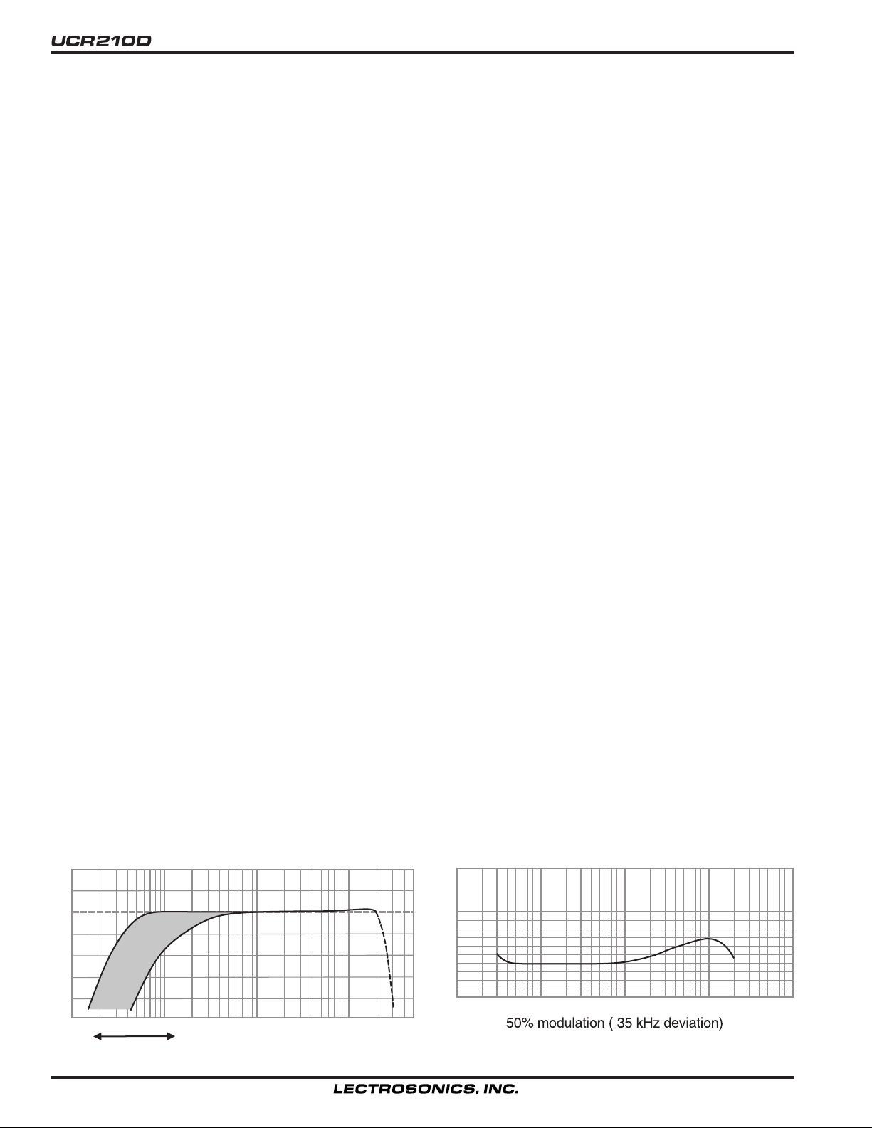
+6
+3
0dB
-3
-6
-9
-12
30 100 1kHz 10k 20k
Adjustable LF Roll-off
12
Specifications subject to change without notice.
System Frequency Response
2.0%
1.0%
0.5%
0%
Typical System THD + Noise
30 100 1kHz 10k 20k
Page 13

UHF Wireless Diversity Receiver
SERVICE AND REPAIR
If your system malfunctions, you should attempt to correct or isolate the trouble before concluding that the equipment needs repair. Make
sure you have followed the setup procedure and operating instructions. Check out the interconnecting cords and then go through the
TROUBLE SHOOTING section in the manual
We strongly recommend that you do not try to repair the equipment yourself and do not have the local repair shop attempt anything other
than the simplest repair. If the repair is more complicated than a broken wire or loose connection, send the unit to the factory for repair and
service. Don’t attempt to adjust any controls inside the units. Once set at the factory, the various controls and trimmers do not drift with
age or vibration and never require readjustment. There are no adjustments inside that will make a malfunctioning unit start
working.
LECTROSONICS’ service department is equipped and staffed to quickly repair your equipment. In warranty repairs are made at no
charge in accordance with the terms of the warranty. Out of warranty repairs are charged at a modest flat rate plus parts and shipping.
Since it takes almost as much time and effort to determine what is wrong as it does to make the repair, there is a charge for an exact
quotation. We will be happy to quote approximate charges by phone for out of warranty repairs.
RETURNING UNITS FOR REPAIR
You will save yourself time and trouble if you will follow the steps below:
A. DO NOT return equipment to the factory for repair without first contacting us by letter or by phone. We need to know the nature of the
problem, the model number and the serial number of the equipment. We also need a phone number where you can be reached 8 am to 4
pm (Mountain Standard Time).
B. After receiving your request, we will issue you a return authorization number (R.A.). This number will help speed your repair through
our receiving and repair departments. The return authorization number must be clearly shown on the outside of the shipping container.
C. Pack the equipment carefully and ship to us, shipping costs prepaid. If necessary, we can provide you with the proper packing
materials. UPS is usually the best way to ship the units. Heavy units should be “double-boxed” for safe transport.
D. We also strongly recommend that you insure the equipment, since we cannot be responsible for loss of or damage to equipment that you
ship. Of course, we insure the equipment when we ship it back to you.
Mailing address: Shipping address: Telephones:
Lectrosonics, Inc. Lectrosonics, Inc. Regular: (505) 892-4501
PO Box 15900 581 Laser Rd. Toll Free (800) 821-1121
Rio Rancho, NM 87174 Rio Rancho, NM 87124 FAX: (505) 892-6243
USA USA
Web: http://www.lectrosonics.com Email: sales@lectrosonics.com
Rio Rancho, NM – USA
13
Page 14

LIMITED ONE YEAR WARRANTY
LIMITED ONE YEAR WARRANTY
The equipment is warranted for one year from date of purchase against defects in
materials or workmanship provided it was purchased from an authorized dealer. This
warranty does not cover equipment which has been abused or damaged by careless
handling or shipping. This warranty does not apply to used or demonstrator equipment.
Should any defect develop, Lectrosonics, Inc. will, at our option, repair or replace any
defective parts without charge for either parts or labor. If Lectrosonics, Inc. cannot
correct the defect in your equipment, it will be replaced at no charge with a similar new
item. Lectrosonics, Inc. will pay for the cost of returning your equipment to you.
This warranty applies only to items returned to Lectrosonics, Inc. or an authorized
dealer, shipping costs prepaid, within one year from the date of purchase.
This Limited Warranty is governed by the laws of the State of New Mexico. It states the
entire liablility of Lectrosonics Inc. and the entire remedy of the purchaser for any
breach of warranty as outlined above. NEITHER LECTROSONICS, INC. NOR
ANYONE INVOLVED IN THE PRODUCTION OR DELIVERY OF THE EQUIPMENT
SHALL BE LIABLE FOR ANY INDIRECT, SPECIAL, PUNITIVE, CONSEQUENTIAL,
OR INCIDENTAL DAMAGES ARISING OUT OF THE USE OR INABILITY TO USE
THIS EQUIPMENT EVEN IF LECTROSONICS, INC. HAS BEEN ADVISED OF THE
POSSIBILITY OF SUCH DAMAGES. IN NO EVENT SHALL THE LIABILITY OF
LECTROSONICS, INC. EXCEED THE PURCHASE PRICE OF ANY DEFECTIVE
EQUIPMENT.
This warranty gives you specific legal rights. You may have additional legal rights which
vary from state to state.
LECTROSONICS, INC.
581 LASER ROAD
RIO RANCHO, NM 87124 USA
November 1, 2001
 Loading...