

Page 1

Quick
Start
Guide
Camera Slot Dual UHF Receiver
SRC
SRC5P
Digital Hybrid Wireless® Technology
Fill in for your records:
Serial Number:
Purchase Date:
U.S. Patent 7,225,135
This guide is intended to assist with
initial setup and operation of your
Lectrosonics product.
For a detailed user manual, download the most current
version at:
www.lectrosonics.com/manuals
14 November 2018
Page 2

Digital Hybrid Wireless
The Lectrosonics Digital Hybrid Wireless® uses innovative technology to
combine the advantages of digital audio with the advantages of analog RF
transmission. The result delivers the superior sound quality of a digital system
and the excellent range of an analog system.
A proprietary algorithm encodes the digital audio information into an analog
format which can be transmitted in a robust manner over an analog FM wireless link. The receiver employs state-of-the-art filters, RF amplifiers, mixers
and detector to capture the encoded signal and a DSP recovers the original
digital audio.
This digital/analog hybrid technique has some very beneficial properties.
Because the information being transmitted is digitally encoded, immunity to
noise is much higher than what a compandor can offer. Because the encoded
audio is sent in analog format, spectral and power efficiency and operating
range are not compromised.
Under weak RF conditions, the received signal degrades gracefully, like an
analog system, delivering as much usable audio as possible at maximum
range. Since the audio is free of compandor artifacts, pumping and breathing
problems are also greatly reduced.
®
LECTROSONICS, INC.2
Page 3

Quick Start Summary
The following checklist includes the minimum required settings to start using
the receiver.
• Install either a battery sled or camera slot adapter kit (see pages 5-6).
• Connect power to the receiver (see page 6-7).
• Set the DIVMODE for single or dual channel operation (see pages 8-9).
• Set the COMPAT (compatibility) mode for the transmitters to be used (see
pages 8-9).
• Find clear operating frequencies for one or both receivers (see page 10).
• Set transmitters on the matching frequencies (see transmitter manual).
• Verify transmitters are set to the same compatibility mode as the receiver
(see transmitter manual).
• Adjust transmitter input gain to match voice level and mic position (see
transmitter manual).
• Adjust receiver output level as needed for the camera or mixer input level
desired (see pages 8-9).
IMPORTANT:
Performance will be degraded if
FREQ.
WARNING
Receiver 2 is set 4.2 to 4.8 MHz higher
than Receiver 1. The LCD will also flash
this message periodically.
www.lectrosonics.com 3
Page 4
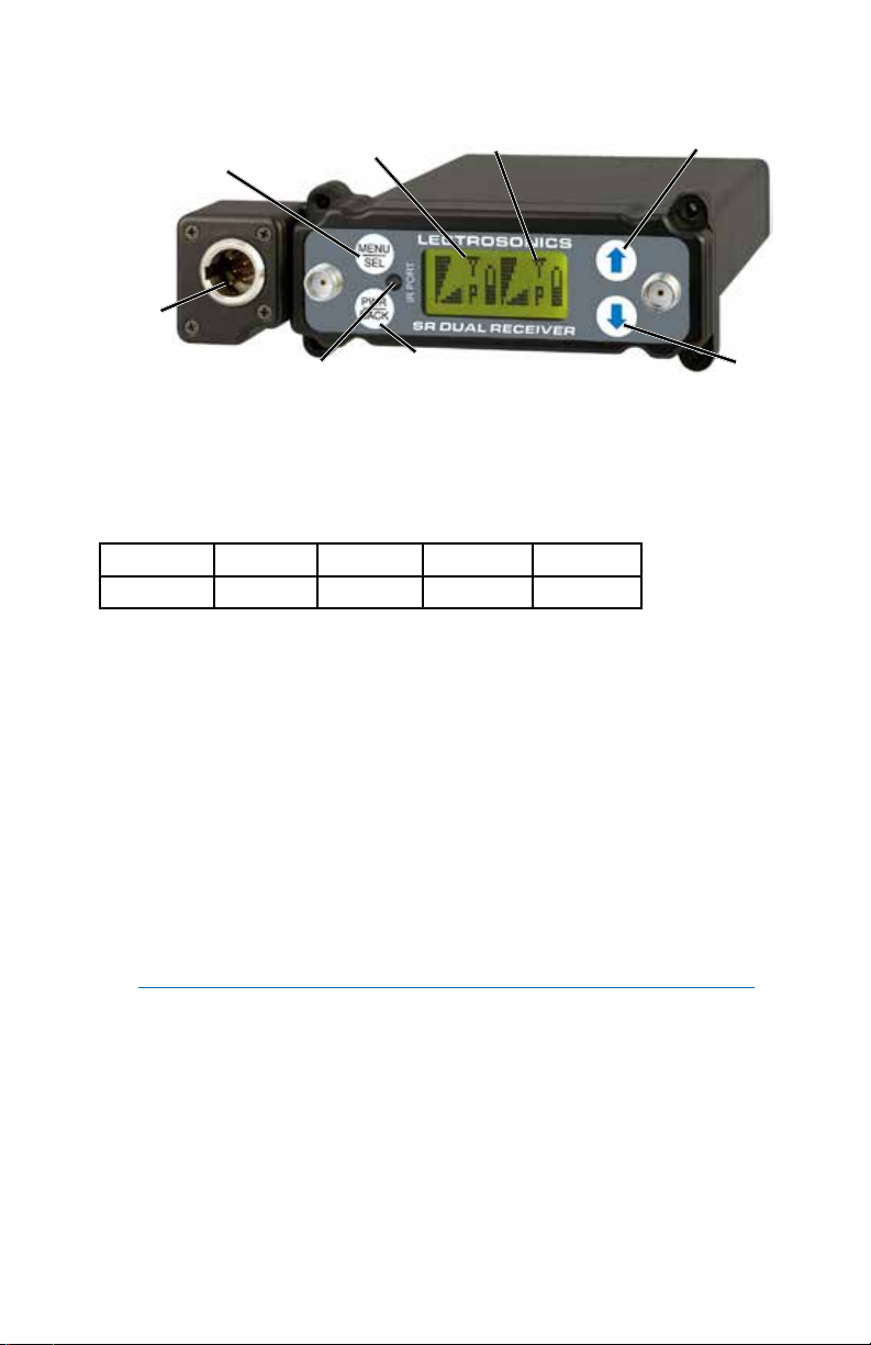
Front Panel Controls and Functions
MENU/SELECT
Secondary
Audio
Output
Button
Receiver 1
Receiver 2
UP Button
Audio Outputs
IR Sync Port
In addition to the audio outputs on the rear panel, the front panel of the receiver provides a second set of outputs through a 5-pin connector. This allows
both audio channels to be connected through external cables for cameras
with only one audio channel enabled in the slot.
The TA5M connector provides two balanced outputs with the following pinouts:
Pin 1 Pin 2 Pin 3 Pin 4 Pin 5
Shields CH1 + CH1 – CH2 + CH2 –
POWER/BACK
Button
LCD Screen
A backlit, graphics-type LCD is used to set up and monitor the receiver. The
Main Window shown above is used during normal operation, to display RF
and audio levels, transmitter battery status, pilot tone status and diversity
activity for both receivers.
MENU/SEL Button
This button is used to select menu items and enter setup screens during
setup.
IR (Infrared) Sync
An IR Sync Port is used for quick setup with transmitters that offer this feature.
Settings for frequency, step size, compatibility mode and talk back are transferred from receiver to transmitter via the IR ports.
DOWN
Button
NOTE: Selected compatibility mode and talk back will only sync if they
are available options on the transmitter you are syncing with.
LECTROSONICS, INC.4
Page 5

PWR/BACK Button
Press the PWR/BACK switch to turn the power on. Press and hold it until the
display goes blank to turn power off. It also functions as a “back” button while
navigating the various menus and setup screens to return to the previous
screen or menu item.
The firmware “remembers” whether the receiver was turned on or off after
power is disconnected, and it returns to that state when power is restored.
This allows the receiver to power up and down as the camera or external supply is turned on and off.
Press the PWR/BACK button from the Main Window to briefly display the
external power voltage.
UP/DOWN Arrow Buttons
The UP and DOWN arrow buttons are used to select various options and
adjust values in the setup screens, and provide secondary functions such as
locking out the panel to guard against accidental changes.
Installing Rear Panel Adapters
Installation of the rear panel output/power adapters is the same for all models.
Panels are held in
place by two Phillips
head screws on the
sides of the housing.
Connections
between the panel
and main circuit
board are made via
miniature mating
connectors.
Align the mating
connectors and slide
the panel straight
into the housing until
the screw holes align
with the housing.
www.lectrosonics.com 5
Page 6

Battery Adapters
Battery sled adapters configure the receiver for standalone use or to provide
battery backup power. Several options are available:
• SRBATTSLEDTOP
• SRBATTSLEDBOTTOM
• SR9VBP (inserts into the SLED adapters)
SRBATTSLEDTOP
SRBATTSLEDBOTTOM
The battery sled adapters accept L and M type video camera rechargeable
batteries and the optional SR9VBP 9 volt battery case.
L or M type video
camera batteries
mount directly onto
the battery sled
SR9VBP
battery
case for
two 9 volt
batteries
The battery sled adapters do not include charging circuitry. Batteries must
be charged with their respective chargers. The adapters include an integral
circuit that automatically selects between the battery and the external source,
whichever delivers the highest voltage.
LECTROSONICS, INC.6
Page 7

External Power Supply
DCR12/A5U
AC power supply with interchangeable
blades/posts for use in Europe, UK,
Australia and USA; 100-240 V, 50/60
Hz input; 12 VDC (regulated), 0.3 A
max. output, 6.0 W. Sold separately.
Main Window (LCD)
Receiver 1 Receiver 2
Diversity
Activity
Transmitter
Battery Level
RF Levels Audio Level
The Main Window displays information concerning the condition of the Pilot
Tone, antenna phase, RF and audio signal levels and battery conditions for
both the receiver and the associated transmitter.
NOTE: When the RATIO DIVERSITY mode is selected, both receivers
are combined to pick up the same transmitter, so the Main Window will
display a single audio channel.
Pilot Tone
Indicator
Receiver 1
RF Level
Pressing the MENU/SEL button accesses the menus and screens for setting
up the receiver and searching for clear frequency channels.
www.lectrosonics.com 7
Receiver 2
RF Level
Audio
Level
Pilot Tone
Indicator
Transmitter
Battery Level
Page 8

Navigating the LCD
Note: Press the BACK button from the Main Window to briefly display
the external power supply voltage.
NOTE: Press the
BACK button from the
Main Window to briefly
display the external
power supply voltage.
Accessing Block 606
NOTE: Block 606 is ONLY AVAILABLE in Bands B1, C1 and C2.
Available from any setup screen that displays the two receiver selection options next to each other, press and hold the DOWN arrow and simulatnously
press PWR/BACK. Using the DOWN arrow, toggle between B1/C1/C2 and
Block 606.
LECTROSONICS, INC.8
Page 9

NOTE: This setting does not appear when
NOTE: To reset the timer, set the TXBAT mode to anything
other than 9VT or AAT, then back to the desired mode.
the MIXMODE is set to DIRECT
COMPAT
Compatibility modes adjust the FM deviation and audio processing (companding) to match other Lectrosonics models and some models from other
manufacturers.
www.lectrosonics.com 9
Page 10

Using SmartTune
SmartTune is the easiest and fastest way to scan the local RF spectrum and
find clear operating frequencies.
Navigate to the
SETUP
SMARTUNE
TX 1
BAND
*NOTE: 23N and B1N (“N” refers to North America) scans skip past TV
Channel 37 (608 to 614 MHz) since it is reserved for radio astronomy
in North America.
OK
SYNC
SMARTUNE screen
and press MENU/
SEL.
The scan can cover all three blocks in the band, or only one
of the three. Use the UP and DOWN arrows to select the
tuning range to be scanned:
B1
B1 - the entire Band B1
21 - block 21 only
22 - block 22 only
23 - block 23 including TV37
23N - block 23 bypassing TV37*
B1N - Band B1 bypassing TV37*
After the scanning is complete, the
newly discovered frequency will be set
automatically. The LCD will then prompt
1
to SYNC the frequency to the matching
transmitter via the IR port (DOWN
ARROW), or to continue by pressing OK
(MENU/SEL).
TM
SMART
TUNE
Use the UP and
DOWN arrows to
1
select receiver 1
or 2, and press
MENU/SEL.
TUNE RX2
NOW? YES
IS TX1
ON? YES
OK
SYNC
RF signal strength
Pilot Tone icons (P)
2
LECTROSONICS, INC.10
After leaving the SYNC screen, the
LCD will ask about setting up the other
receiver. Use the UP and DOWN arrows to
select YES to tune the other receiver, then
press MENU/SEL to continue.
Turn on the transmitter that matches the
first receiver that was tuned. Use the
UP and DOWN arrows to select YES and
press MENU/SEL.
After the scanning is complete, the
newly discovered frequency will be set
automatically. The LCD will then prompt
to SYNC the frequency to the matching
transmitter via the IR port (DOWN
ARROW), or to continue by pressing OK
(MENU/SEL).
Press the BACK button several times
to return to the Main Screen and verify
that both transmitters show a strong RF
signal strength and that the Pilot Tone
icons are NOT blinking.
Page 11

Manual Scanning
26
BD
C7
25
Scan Window
Zoom View Window
Previously tuned
frequency
RF activity
Dashed line (cursor)
level
shows the currently
Block
Freq
in hex
selected receiver
Press both UP and DOWN
arrows on control panel to
switch to the Zoom View
Press the BACK
button to return
to the Scan View
Window
Cursor (center bar)
Block
Freq in
hex
First, turn off all of the transmitters you intend to use with the receiver.
Navigate to the SETUP/SCAN screen and press the MENU/SEL button to
start the scanner. The display will switch to the Scan Window (see illustration
above) and start scanning immediately. Allow the receiver to scan across the
entire tuning range at least once, then press the MENU/SEL button to stop
the scanning.
Scroll through the screen with the UP and DOWN buttons and find a frequency where no (or very weak) RF signals are present. Press the PWR/BACK
button to set the receiver to this new frequency.
Press both the UP and DOWN buttons at the same time to switch to the
Zoom View Window (see illustration above). In this view, the cursor remains
fixed in the center of the screen and the background scrolls behind it. The
frequency can be stepped up and down in 100 kHz increments using the UP
and DOWN arrow buttons.
When the receiver is configured for SWITCHED diversity (dual channel
mode), two cursors will appear when the scanning is stopped. Press MENU/
SEL to toggle between the two receivers. The cursor for the selected receiver
will be a dashed rather than solid line. Select each receiver and use the UP
and DOWN buttons to locate a frequency with no (or very weak) RF activity.
Keep the frequencies of the two receivers at least 700 kHz apart to minimize
de-sensing (short range) issues. This spacing is a “worst case” approximation
assuming the transmitters are about 25 feet from the receiver antennas.
Data gathered during a scan is stored until it is intentionally erased or the
power is turned off. Previous data will remain and subsequent scans can be
made to search for additional signals or to accumulate higher peaks.
To clear the scan memory and screens, press the back button several times to
return to the Main Window, then press and hold the PWR/BACK button briefly.
As soon as Powering off... appears on the display, release the button. The
receiver will remain turned on, and the scan data will be erased.
Set your transmitter to the same frequency as shown on the receiver display,
turn the transmitter on and verify that a strong RF signal is present.
www.lectrosonics.com 11
Page 12

LIMITED ONE YEAR WARRANTY
The equipment is warranted for one year from date of purchase against defects in
materials or workmanship provided it was purchased from an authorized dealer. This
warranty does not cover equipment which has been abused or damaged by careless
handling or shipping. This warranty does not apply to used or demonstrator equipment.
Should any defect develop, Lectrosonics, Inc. will, at our option, repair or replace any
defective parts without charge for either parts or labor. If Lectrosonics, Inc. cannot
correct the defect in your equipment, it will be replaced at no charge with a similar new
item. Lectrosonics, Inc. will pay for the cost of returning your equipment to you.
This warranty applies only to items returned to Lectrosonics, Inc. or an authorized
dealer, shipping costs prepaid, within one year from the date of purchase.
This Limited Warranty is governed by the laws of the State of New Mexico. It states the
entire liablility of Lectrosonics Inc. and the entire remedy of the purchaser for any
breach of warranty as outlined above. NEITHER LECTROSONICS, INC. NOR
ANYONE INVOLVED IN THE PRODUCTION OR DELIVERY OF THE EQUIPMENT
SHALL BE LIABLE FOR ANY INDIRECT, SPECIAL, PUNITIVE, CONSEQUENTIAL,
OR INCIDENTAL DAMAGES ARISING OUT OF THE USE OR INABILITY TO USE
THIS EQUIPMENT EVEN IF LECTROSONICS, INC. HAS BEEN ADVISED OF THE
POSSIBILITY OF SUCH DAMAGES. IN NO EVENT SHALL THE LIABILITY OF
LECTROSONICS, INC. EXCEED THE PURCHASE PRICE OF ANY DEFECTIVE
EQUIPMENT.
This warranty gives you specific legal rights. You may have additional legal rights which
vary from state to state.
 Loading...