

Page 1
SRc5P and SRc
Camera Slot Dual UHF Receiver
TECHNICAL DATA
• Fits camera “slots,” Lectrosonics Duopack
adapter and Octopack multicoupler, and
operates stand-alone with various adapters
• Tunes over a 76 MHz range* (3 blocks)
• Dual receiver design for two channels with
phase switched diversity or single channel
with ratio diversity operation
• Digital Hybrid Wireless® with compatibility
modes for use with earlier transmitters
The SRc5P and SRc design includes two separate
receivers built into a single, ultra compact housing with
adapters for video camera receiver slots and for standalone use. Digital Hybrid Wireless® technology provides
superb, compandor-free audio quality and compatibility
with other wireless systems. The RF performance is
extremely stable over a very wide temperature range,
making the receiver perfectly suited to the rough environmental conditions found in field production.
DSP compatibility modes allow the receiver to be used
with a variety of Lectrosonics systems, other brands of
wireless systems and with Lectrosonics IFB transmitters.
Digital Hybrid Wireless
that combines digital audio with an analog FM radio
link to provide both outstanding audio quality and
exemplary, noise-free RF performance.
Using a patented algorithm to encode 24-bit digital
audio information in the transmitter into an analog
format, the encoded signal is then transmitted over an
analog FM wireless link.
®
is a revolutionary design
• Tracking front-end filters for high
performance in tough RF environments
• LCD with RF spectrum scanning
• SmartSquelch
TM
DSP-controlled, noise based
filtering and squelch
• DSP-based pilot tone for squelch control
• IR sync port for quick transmitter setup
• SmartTune
TM
operation for quick and
confident frequency selection
The front panel features a menu-driven LCD interface
and four membrane switches which are used to view
and alter settings. The main LCD window displays the
pilot tone indicator, diversity activity, RF level, audio level
and transmitter battery status for both receivers. To find
clear operating frequencies, a built-in spectrum analyzer
scans across the tuning range of the receiver and displays a histogram of RF activity across the band. Areas
with little or no RF activity are easily recognizable.
The two internal receivers can be operated separately,
each using switching, antenna combining diversity, or in
tandem with ratio diversity reception. The audio outputs
of the receivers can be mixed internally, or left separated
for discrete recording tracks or external mixing.
A variety of output adapters and mounting options are
available for camera slot operation. The receivers are
powered from an external 7 to 18 volt DC source. The
SRC5P model provides a 5-pin connector next to the
control panel with audio output from both channels in addition to the camera slot outputs.
At the receiver, the signal is then decoded to restore
the original digital audio. This process eliminates
compandor artifacts and produces an audio
frequency response flat to 20 kHz.
(US Patent 7,225,135)
*Tuning range varies slightly in different bands
Rio Rancho, NM, USA
www.lectrosonics.com
Page 2
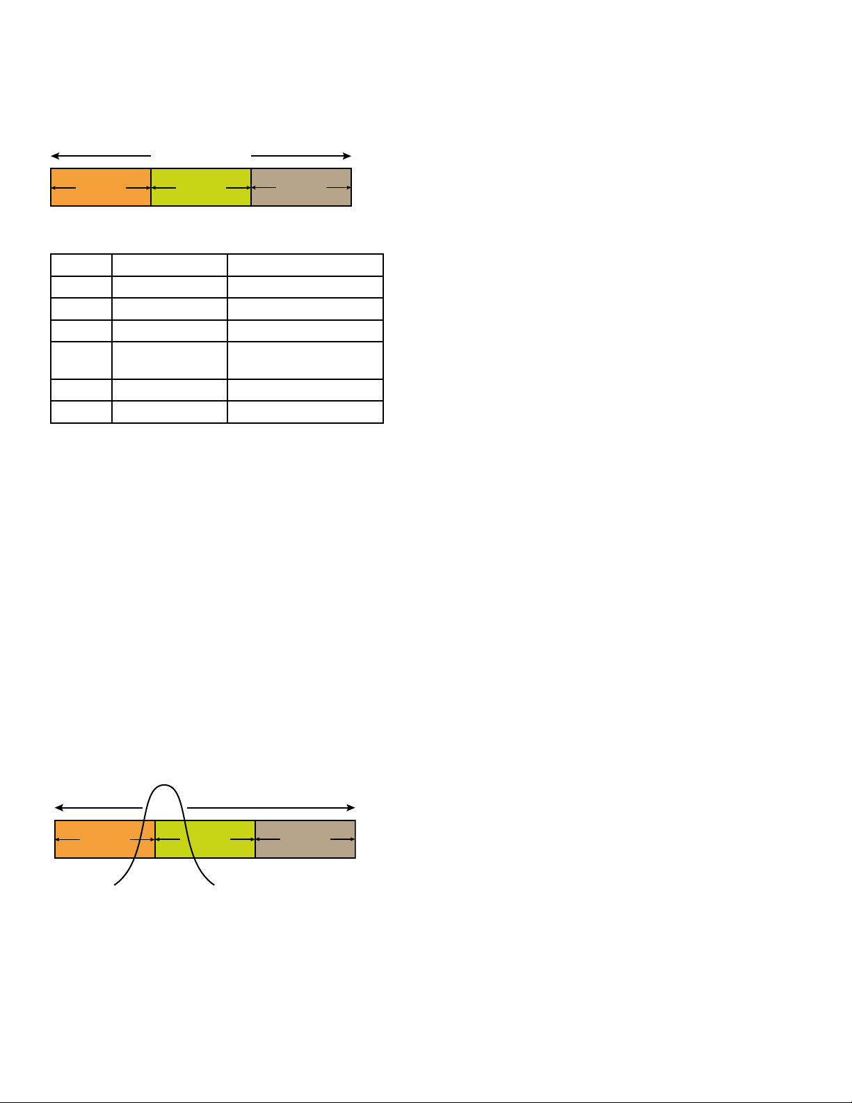
Three Block Tuning Range
TUNING RANGE
The SRC & SRC5P receivers tune across a range of
over 76 MHz. This tuning range covers three standard
Lectrosonics frequency blocks.
BLOCK
BLOCK
BLOCK
IF (Intermediate Frequency) Filters
Following the front-end, the incoming RF signal in each
receiver is mixed down to a lower frequency for additional filtering with two SAW (surface acoustic wave) filters.
The use of two filters significantly increases the depth
of filtering while preserving sharp skirts, constant group
delay, and wide bandwidth.
Tuning ranges are available covering standard blocks
as follows:
Band Blocks Covered Freq. (MHz)
A1 470, 19, 20 470.100 - 537.575
B1 21, 22 23 537.600 - 614.375
B2 22, 23, 24 563.200 - 639.975
Block
606
C1 24, 25, 26 614.400 - 691.175
C2 25, 26, 27 640.000 - 716.775
23, 24
606.000 - 631.500
RF Front-End with Tracking Filter
A wide tuning range is helpful in finding clear frequencies for operation, however, it also allows a greater range
of interfering frequencies to enter the receiver. The UHF
frequency band, where almost all wireless microphone
systems operate, is heavily populated by high power TV
transmissions. The TV signals are immensely more powerful than a wireless microphone transmitter signal and
will enter the receiver even when they are on significantly
different frequencies than the wireless system. This powerful energy appears as noise to the receiver, and has
the same effect as the noise that occurs with extreme
operating range of the wireless system (noise bursts and
dropouts). To alleviate this interference, front-end filters
are needed in the receiver to suppress RF energy below
and above the operating frequency.
Each receiver employs a variable frequency, tracking
filter in the front-end section (the first circuit stage following the antenna). As the operating frequency is changed,
the filters re-tune to stay centered over the selected carrier frequency.
BLOCK
In the front-end circuitry, a tuned tracking filter is followed
by an amplifier and then another tuned tracking filter to
provide the selectivity needed to suppress interference,
yet provide a wide tuning range and retain the sensitivity
needed for extended operating range.
BLOCK
BLOCK
Digital Pulse Counting Detector
Following the IF section, the receiver uses an elegantly
simple, yet highly effective digital pulse counting detector to demodulate the FM signal to generate the audio,
rather than a conventional quadrature detector. This
unusual design eliminates thermal drift, improves AM
rejection, and provides very low audio distortion.
DSP-Based Pilot Tone
The Digital Hybrid system design uses a DSP generated
ultrasonic pilot tone to reliably mute the audio when no
RF carrier is present. The pilot tone must be present in
conjunction with a usable RF signal before the audio output will be enabled. 256 pilot tone frequencies are used
across each 25.6 MHz block within the tuning range of
the system. This alleviates erroneous squelch activity in
multichannel systems where a pilot tone signal can appear in the wrong receiver via IM (intermodulation).
Automatic Power State Restoration
The firmware “remembers” whether it was turned on or
off when power is disconnected and returns to that state
when power is restored.
SmartSquelch
A DSP-based algorithm named SmartSquelchTM optimizes
the receiver performance in very weak signal conditions.
The RF level and supersonic noise in the audio are continuously monitored to determine the appropriate noise
reduction needed and the point at which squelch (complete
muting of the audio) is necessary.
™
SmartTune™ Frequency Selection
SmartTune™ simplifies setup by scanning the tuning range
of the receiver or a selected frequency block, and automatically setting a channel to the best available frequency.
A prompt appears, reminding the user to use IR sync or
manual settings to tune the transmitter to the selected
frequency, then turn it on so the receiver sees it. Then, a
prompt asks if the process should continue for the second
channel. This process allows very quick and accurate tuning, whatever the RF environment.
Page 3

Front Panel Controls and Functions
Receiver 1 Receiver 2
Transmitter
Battery Level
The control panel is a rug-
Receiver 1
RF Level
ged, dust and water resistant design with membrane
switches for the control interface. A backlit, graphicstype LCD is used to set up
and monitor the receiver.
Navigation through the
menus is straightforward
Receiver 2
RF Level
Audio Level
with text prompts for value
and mode selections. In the ratio diversity mode, the
Main Window displays audio levels, transmitter battery
status, pilot tone status and RF level activity for both
receivers, with a single audio channel display.
The 5P version of the SRc receiver is intended for use
with cameras that do not have both audio channels
enabled in the camera slot. In addition to the audio outputs on the rear panel, a second set of outputs are also
provided through a 5-pin connector on an adapter next to
the control panel. The TA5M connector next to the control
panel provides two balanced outputs with the following
pinouts:
Pin 1 Pin 2 Pin 3 Pin 4 Pin 5
Shields CH1 + CH1 – CH2 + CH2 –
Rear Panel and Slot Adapter Kits
Several different rear panel adapters are available to
configure the receiver for popular camera slots and for
stand-alone use. The rear panels are held in place by
two screws and are easily changed. Camera slot adapter
kits include top panel bezels with hardware for a secure
fit into the camera body.
SuperSlot adapter
SRSUPER adapter kit
SREXT adapter
SRSNY adapter
Battery Adapter
The receiver can be powered
with an optional battery “sled”
adapter that accepts standard
“L” and “M” style rechargeable
batteries. The adapter includes
an integrated SREXT plate for the
rear panel audio outputs. Typical
runtime with a 7.2 V, 2200 mA “L”
style battery is approx. 11 hours.
External Power Supply
DCR12/4AU
NOTE: SRSUPER
adapter kit for
®
Unislot
slots such as
those provided
on Ikegami
and Panasonic
cameras, as well as
the SL-6 by Sound
Devices
bezel, hardware
and rear panel
DB25 connector
wired for power and
audio connections.
camera
®
®
®
. Includes
AC power supply with
standard C14 inlet and
locking LZR coaxial
output connector. Interchangeable blades/posts
for use in Europe, UK,
Australia and USA; 100240 V, 50/60 Hz input; 12
VDC (regulated), 0.3 A
max. output, 6.0 W.
Page 4

m
Specifications and Features
Operating Frequencies:
Operating Frequencies:
Band A1: 470.100 - 537.575 MHz
Band B1: 537.600 - 614.375 MHz
Band B2: 563.200 - 639.975 MHz
Block 606: 606.000 - 631.500 MHz
Band C1: 614.400 - 691.175 MHz
Band C2: 640.000 - 713.900 MHz /716.775 MHz
selectable
Frequency selection steps: Selectable; 100 kHz or 25 kHz
Receiver Type: Dual conversion, superheterodyne
IF Frequencies: Ch.1: 248.450 MHz and 350.000 kHz
Ch. 2: 243.950 MHz and 250.000 kHz
Frequency Stability: ±0.001 %
Front end bandwidth: 20 MHz @ -3 dB
Sensitivity
20 dB SINAD: 1.0 uV (-107 dBm), A weighted
60 dB Quieting: 2.2 uV (-100 dBm), A weighted
Squelch quieting: Greater than 100 dB typical
AM rejection: Greater than 60 dB, 4 uV to 1 Volt
Modulation acceptance: 85 kHz
Image and spurious rejection: 85 dB
Third order intercept: 0 dBm
Diversity method: SmartDiversity
combining or Ratio Diversity using both
receivers for a single audio channel
FM Detector: Digital Pulse Counting Detector operating
at 250 and 350 kHz
RF spectrum analyzer: Coarse and ne scanning modes for
RF spectrum site survey
Antenna inputs: 50 Ohm; SMA female connectors
Audio output connectors: • Interchangeable D connector adapters
for camera slot interfaces
• Dual TA3 male (mini XLR) balanced
output adapter
• Balanced output adapter with xed
cables
Front panel audio output (5P model): Control panel TA5M with two balanced
outputs
Audio output level: Adjustable -50 to +5 dBu in 1 dB steps;
unbalanced output is 6 dB lower
Audio channel crosstalk: -80 dB or better
Front Panel Controls and Indicators:
• Sealed panel with membrane switches
• LCD monitors pilot tone; antenna phase,
receiver battery level; transmitter battery
status; audio level, RF level
Audio test tone: 1 kHz, -50 dBu to +5 dBu output (bal);
1% THD
FCC Notice
NOTE: This equipment has been tested and found to
comply with the limits for a Class B digital device, pursuant to part 15 of the FCC Rules. These limits are designed to provide reasonable protection against harmful
interference in a residential installation. This equipment
generates, uses and can radiate radio frequency energy
and, if not installed and used in accordance with the
instructions, may cause harmful interference to radio
communications. However, there is no guarantee that
interference will not occur in a particular installation. If this
equipment does cause harmful interference to radio or
television reception, which can be determined by turning
TM
phased antenna
Transmitter battery type Selection: 9V alkaline, 9V lithium, AA alkaline,
AA lithium, NiMH
Phase invert: Audio output phase normal or inverted
Compatibility modes:
NA HYBR North American Digital Hybrid Wireless
NU HYBR ETSI Compliant Nu Digital Hybrid Wireless
MODE 3 Other manufacturer*
200 SER 200 Series transmitters
100 SER 100 Series transmitters
MODE E Other manufacturer*
EU HYBR European Digital Hybrid Wireless
300 SER 300 Series transmitters (European)
MODE 7 Other manufacturer*
MODE 6 Other manufacturer*
IFB SER Standard IFB mode
®
®
*Contact the factory for details on other manufacturers
SmartNR (noise reduction): OFF, NORMAL, FULL modes
(available in Digital Hybrid mode only)
Audio Performance (overall system):
Frequency Response: 32 Hz to 20 kHz (+/- 1dB)
THD: 0.15% (system) typical in Digital Hybrid
mode
Smart-NRNo Limit-
System Dynamic Range:
(Note: The dual envelope “soft” limiter provides
exceptionally good handling of transients using
variable attack and release time constants.
Once activated, the limiter compresses 30+ dB
of transmitter input range into 4.5 dB of receiver
output range, thus reducing the measured gure
for dynamic range with no limiting by 4.5 dB.
Rear Panel Controls and features: • Audio output connectors;
• External DC input;
Powering and current consumption: Min. 7 V to max. 18 Volts DC; 2.6 W
• 145 mA at 18 VDC
• 290 mA at 7 VDC
Runtime with SRBATTSLED adapter: 7.2 V, 2200 mAH “L” style battery will
typically provide over 7 hours of operation
Transmitter battery level tracking: LCD display with battery icon or timer
readout
Operating temperature: -20°C to +50°C
Weight: 225 grams (7.9 ozs.) with SREXT adapter
Overall dimensions: 2.92” wide x 1.22” high x 4.93” deep
(with SREXT adapter) (74 mm x 31 mm x 125 mm)
Specications subject to change without notice
OFF 103.5 108.0
NOR
MAL
FULL 108.5 113.0
)
-
107.0 111.5
ing
W/ Limiting
the equipment off and on, the user is encouraged to try
to correct the interference by one or more of the following measures:
• Reorient or relocate the receiving antenna.
• Increase the separation between the equipment
and receiver.
• Connect the equipment into an outlet on a circuit
different from that to which the receiver is connected.
• Consult the dealer or an experienced radio/TV
technician for help.
Changes or modifications to this equipment not expressly approved by Lectrosonics, Inc. could void the user’s
authority to operate it.
®
581 Laser Road NE • Rio Rancho, NM 87124 USA • www.lectrosonics.com
(505) 892-4501 • (800) 821-1121 • fax (505) 892-6243 • sales@lectrosonics.co
13 November 2018
 Loading...