

Page 1

DocuCam
™
SR170LE RECEIVER
CONTROLS & CONNECTORS
FRONT PANEL
POWER
The LED glows when the external power source is properly connected. If this lamp is very dim or does
not light up, check the external power source and connections.
RF
This LED lights when the companion transmitter is turned on and there is sufficient radio signal for good
receiver operation. Internal circuits monitor both signal level and interference levels and decide if the
transmitted signal is strong and “clean” enough for satisfactory operation. If not, the RF lamp will go out
and the receiver will “squelch”, shutting off the sound output. This action is automatic and requires no
user adjustment.
MODULATION
-20 — This LED lights when the audio signal is 20 dB below full modulation. It is a general
indicator of minimum modulation required for a good signal to noise ratio. The LED
should flicker or stay lit when the user is speaking into the microphone.
0dB — This LED lights when the audio signal is at full modulation. This LED should only light
during the loudest “peaks” in the audio signal.
These LEDs continuously monitor the modulation (audio level) of the received signal from the transmitter
and are used when making initial adjustment to the transmitter. See the transmitter instructions regarding
adjustment of audio input gain on the transmitter.
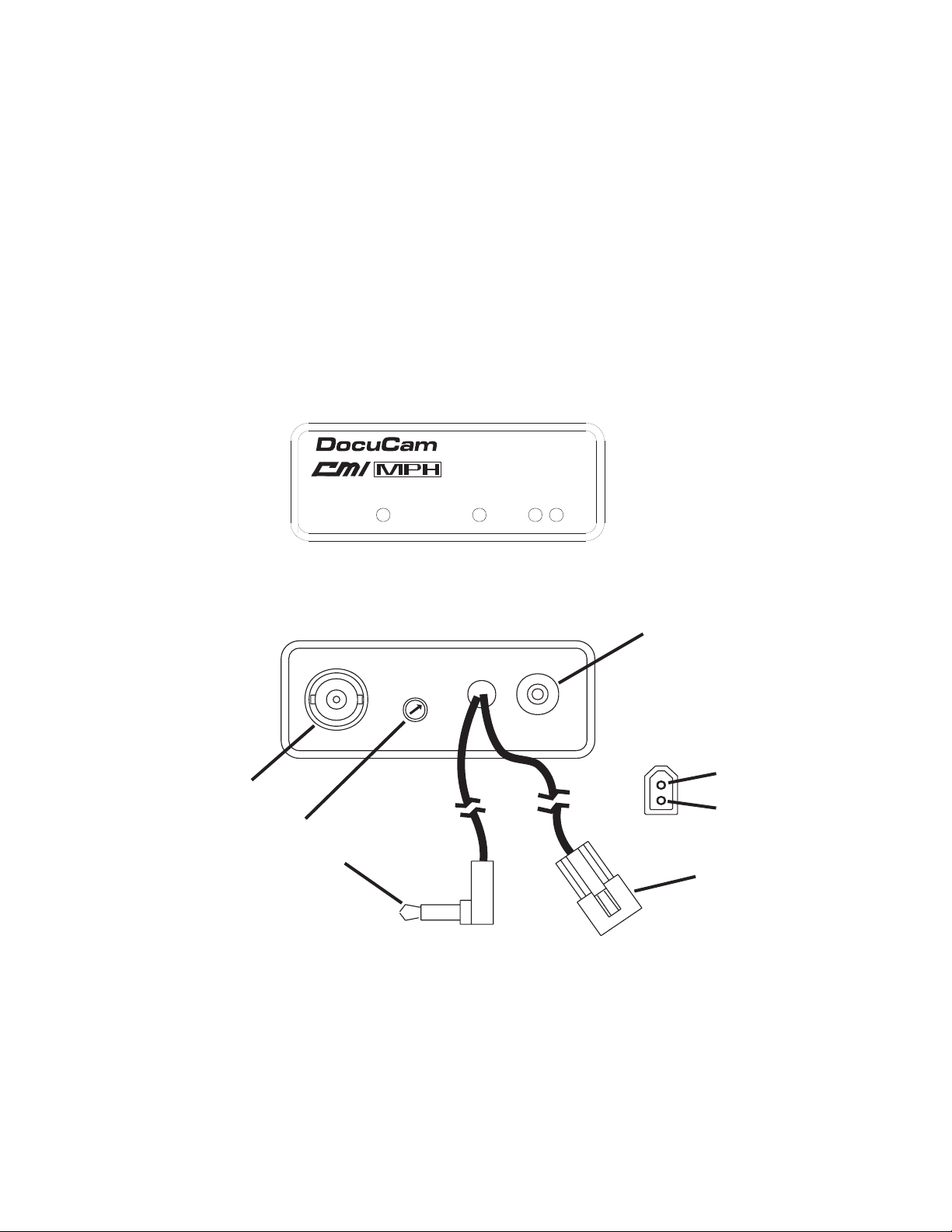
REAR PANEL
AUDIO OUTPUT PLUG
A standard 3.5mm mini-phone plug that connects to the VCR audio input.
AUDIO OUTPUT LEVEL CONTROL
An output attenuator trim pot used to regulate the output audio level of the receiver. When adjusted fully
counter-clockwise, the output will be the same as from a typical microphone. When adjusted fully clockwise, the output level will be at a “line” level (-10dB). Intermediate settings are sometimes necessary due
to the variations in different input compressors and ALC (automatic level control) circuits on different
VCR’s and audio inputs.
ANTENNA
A standard BNC connector accepts RF input from an external antenna. 50 Ohm impedance.
12V DC POWER
Apply 12 Volt DC power to this jack. Power consumption is 100 mA, maximum. Observe the polarity of
the connector illustrated on the next page. The receiver is protected from damage that may be caused by
reverse polarity.
If reverse polarity is applied, the receiver will simply not operate (no LEDs). Re-connect the lead for
proper operation.
Page 2
5
RELAY CONTACT
This locking micro-jack provides a relay driver (open collector) triggered by the RF circuit in the receiver.
When the RF LED lights up, the center conductor on the jack is shunted to ground. This provides a
switch to trigger external devices in conjunction with the RF carrier from the transmitter. For example, the
VCR may be activated to start tape movement when the transmitter is turned on outside of the patrol car.
There is a slight delay in the turn-on and turn-off. This is intended to prevent interruptions in recording, or
accidental turn-on that may be caused by RF interference.
Maximum voltage for the relay power supply cannot exceed the receiver power supply voltage. Maximum
current handling capacity in the “ON” (shunted) mode is 300 mA. This limit is set by an auto-reset thermal
fuse. Reverse polarity protection is provided by a diode and the thermal fuse. If the protection circuitry is
activated, it may be necessary to wait 10 seconds or so after power is removed to allow the thermal fuse
to reset.
F R O N T P A N E L
®
RF
POWER
R E A R P A N E L
by LECTROSONICS
-20
SR170LE
0dB
R E L A Y C O N T A C T
1 2 V
D C P O W E R
N E G A T I V E ( - )
P O S I T I V E ( + )
A N T E N N A
0 O H M B N C
L E V E
A U
D I O O U T P U T
L C O N T R O L
A U D I O
O U T P U T
3 . 5 m m M I N I P L U G
The DocuCam SR170LE receiver is manufactured by:
LECTROSONICS, INC.
PO BOX 15900
RIO RANCHO, NM 87174
Phone: (505) 892-4501
WATS: (800) 821-1121
FAX: (505) 892-6243
 Loading...