

Page 1

SR170 AC
RECEIVER
OPERATING INSTRUCTIONS
and trouble-shooting guide
LECTROSONICS, INC.
Rio Rancho, NM
Page 2

INTRODUCTION
The SR170 AC receiver design is the result of surveying the needs of professional video producers,
audio visual coordinators, and many others in the industry. Numerous conversations with dealers and
end-users have developed the parameters for the design.
The SR170 AC receiver is a fixed frequency design utilizing a quartz crystal oscillator. This assures
that the frequency will not drift and also eliminates the need to "tune" or adjust the receiver every time it
is used. This is the preferred design that professionals have chosen.
Custom made toroidal filters in the front-end reject adjacent channels to avert interference. A noise
reduction "compandor" is used in all Pro-Series systems to suppress audio noise without impairing the
natural dynamics of the audio signal. The receiver is housed in an aluminum extrusion with rugged
connectors for years of professional performance. The SR170 AC receiver is compatible with all
Lectrosonics high-band receivers.
While the SR170 AC was designed primarily to meet the needs of video producers, it has many other
applications in public address.
TABLE OF CONTENTS
INTRODUCTION .......................................... 1
RECEIVER FRONT PANEL ................................... 2
RECEIVER REAR PANEL .................................... 3
SYSTEM SETUP AND OPERATION ............................ 4
INDICATORS ............................................. 4
ANTENNA USE AND PLACEMENT ............................. 5
TROUBLESHOOTING ....................................... 6
REPLACEMENT PARTS and ACCESSORIES ..................... 6
SERVICE AND REPAIR ..................................... 7
RETURNING UNITS FOR REPAIR ............................. 7
SR170 AC SPECIFICATIONS AND FEATURES .................... 8
WARRANTY ........................................ Back cover
1
Page 3
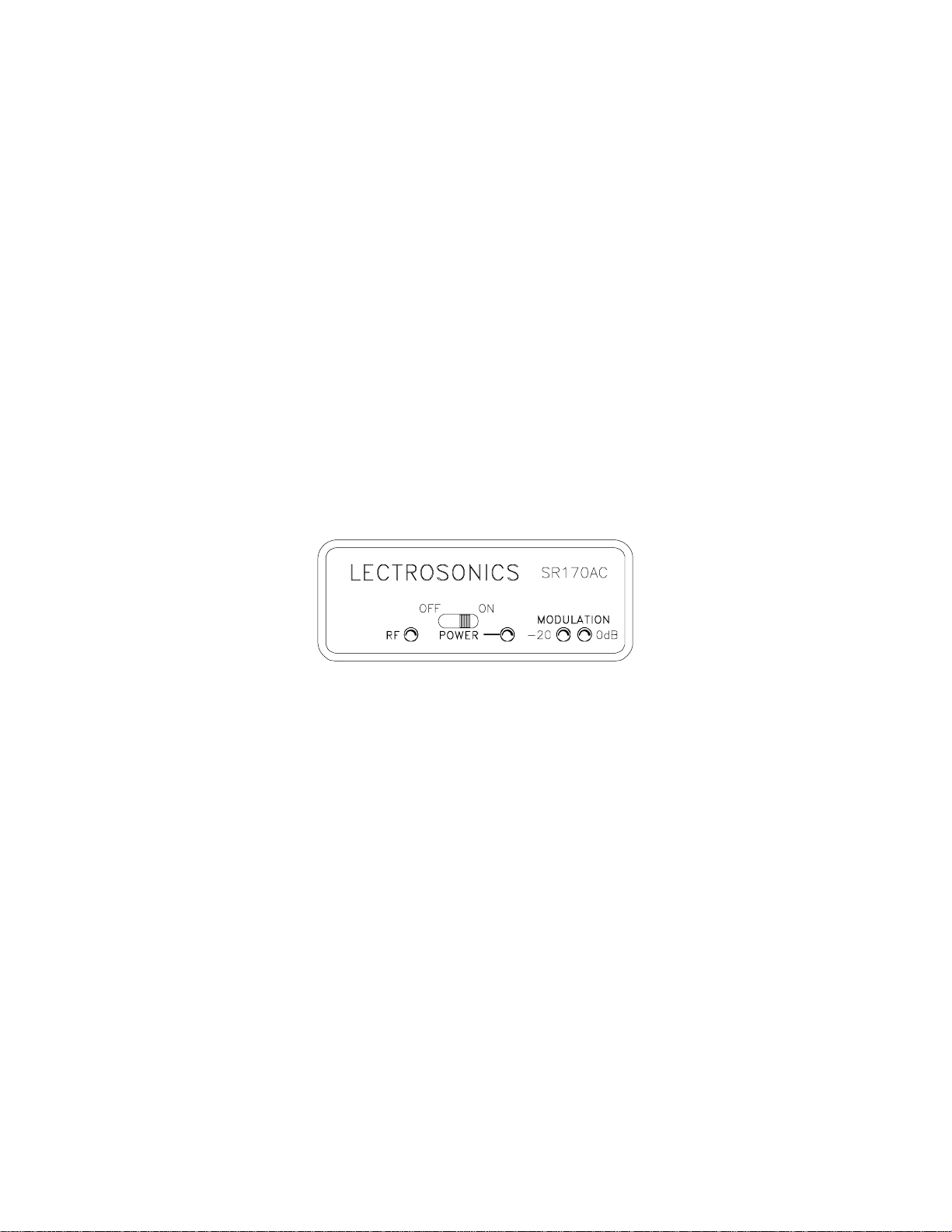
RECEIVER FRONT PANEL
MODULATION - Indicates the modulation (audio level) of the incoming signal - see transmitter manual
for proper adjustment of transmitter "MIC LEVEL" or "GAIN." The -20 lamp should flicker, or stay lit as
you speak into the microphone. The 0dB lamp is a "peak" indicator showing that the audio gain in the
transmitter is set too high. It is normal, however, to see an occasional flicker of the 0dB lamp.
POWER OFF-ON Switch - This slide switch turns the power off and on.
POWER LED - Glows when the switch is in the "ON" position and the power source is good, or when
the AC adapter is properly connected. If this LED is very dim or does not light up when the switch is
turned on, check the power source.
RF LED - Lights when the transmitter is turned on. When the carrier signal from the transmitter is too
weak to produce a clean audio signal the lamp will go out.
Figure 1 -SR170AC Front Panel
2
Page 4

RECEIVER REAR PANEL
ANTENNA terminal - A standard BNC connector compatible with the supplied A-185BNC telescoping
antenna.
12 VDC INPUT - Connect the power supply here - the CH-12 AC adapter is supplied with the receiver
for powering the unit from a 110V AC source. The receiver may also be powered from 12 volt DC
sources using the correct plug (Switchcraft S-760 power plug); the center pin on the receiver jack is
positive (+).
AUDIO OUTPUT (1/4" PHONE JACK) - This is the audio output that should connect into your VCR,
camcorder or sound system. It is a standard 1/4" phone jack which is the same as you will find on
most industrial video equipment. Being such a common type of connector, many different adapters and
cords are available from local audio or electronics dealers in your area, or from the factory.
AUDIO OUTPUT LEVEL CONTROL - An attenuator used to regulate the output level of the receiver.
When fully counter-clockwise in the "MIN" position, the output of the mini jack on the front panel will be
the same as a typical microphone. Fully clockwise in the "MAX" position, the output level will be at a
normal 0dB line level. Intermediate settings are sometimes necessary due to the variations in different
input compressors and ALC (automatic level control) circuits on different VCR’s and audio inputs.
Figure 2 - SR170AC Rear Panel
3
Page 5

SYSTEM SETUP AND OPERATION
1) CONNECT POWER CORD - On your external power source, be sure the center pin is
positive(+).
2) ATTACH AND EXTEND THE ANTENNA
3) CONNECT THE AUDIO CABLE
4) SET FRONT PANEL SWITCH TO "ON."
Check to see that the red POWER LED lights up.
5) ADJUST TRANSMITTER "GAIN."
This is perhaps the most important step in the set up procedure. (see your transmitter manual
for specific instructions on the proper gain adjustment of your transmitter)
6) ADJUST AUDIO OUTPUT LEVEL CONTROL according to the type of input on your equipment.
The input levels on different VCR’s and PA equipment vary which may require that you set the
OUTPUT control in an intermediate position somewhere in between the MIN and MAX positions of
the knob. Try different settings and listen to the results. If the output of the receiver is too high,
you may hear distortion or a loss of the natural dynamics of the audio signal. If the output is too
low, you may hear steady noise (hiss) along with the audio.
INDICATORS
RF - This red LED lights up when the transmitter is turned on. This indicates that the receiver is getting
an adequate RF signal (carrier) from the transmitter.
POWER - This red LED lights up when the receiver is properly connected to a power supply and
switched on.
MODULATION - The red LED (marked -20) lights up when an audio signal is present at an adequate
level to produce a good signal to noise ratio. The red LED (marked 0dB) lights up when the audio
level is too high and is being compressed in the transmitter. An extremely high audio level may also
cause distortion.
REVIEW THE TRANSMITTER INSTRUCTION MANUAL FOR PROPER ADJUSTMENT
AND SETUP OF THE TRANSMITTER MIC LEVEL
4
Page 6

ANTENNA USE AND PLACEMENT
Connect the antenna to the rear panel jack. Extend the antenna fully. Position the antenna so that it is
not touching or within 3 or 4 feet of large metal surfaces. It is also good practice to position the
receiver so that there is a direct "line of sight" between the transmitter and the receiver antenna.
A wireless transmitter sends a radio signal out in all directions. This signal will often bounce off nearby
walls, ceilings, etc. and a strong reflection can arrive at the receiver antenna along with the direct
signal. If the direct and reflected signals are out of phase with each other a cancellation may occur.
The result would be a "dropout." A dropout sounds like either audible noise (hiss), or in severe cases,
may result in a complete loss of the sound when the transmitter is positioned in certain locations in the
room. A dropout normally sounds like "hum" or "hiss." Moving the transmitter even a few inches will
change the sound of the hum or hiss, or eliminate it. A dropout situation may be either better or worse
as the crowd fills and/or leaves the room.
In the event that you do encounter a dropout problem, first try moving the receiver/antenna at least 3 or
4 feet from where it was. This may alleviate the dropout problem. If dropouts are still a problem, try
moving the receiver and/or the antenna to an entirely different location in the room.
Lectrosonics transmitters radiate more power, and the receivers are more sensitive than any other on
the market. This reduces dropouts to an insignificant level. If, however, you do encounter dropouts
frequently, call the factory. There is probably a simple solution.
5
Page 7

TROUBLESHOOTING
Before going through the following chart, be sure that you have a good battery in the transmitter. It is
important that you follow these steps in the sequence listed.
SYMPTOM POSSIBLE CAUSE
TRANSMITTER BATTERY LED OFF 1) External LED is turned off. Check internal slide
switch.
2) Battery is inserted backwards.
3) Battery is dead.
NO TRANSMITTER MOD LEVEL LEDs 1) Gain control turned all the way down.
2) Battery is in backwards. Check power LED.
3) Mic capsule is damaged or malfunctioning.
RECEIVER RF LAMP OFF 1) Transmitter not turned on.
2) Transmitter battery is dead.
3) Receiver antenna missing or improperly positioned.
4) Transmitter and receiver not on same frequency.
Check labels on transmitter and receiver.
5) Operating range is too great.
NO SOUND AND RECEIVER MOD
LEVEL LEDs ARE OFF 1) Transmitter audio muted. Check to see that the audio
is not muted on your transmitter, if this feature is
available on your model transmitter.
NO SOUND BUT RECEIVER MOD
LEVEL LEDs ARE ON 1) Receiver audio is muted. Refer to receiver manual.
2) Receiver audio output is disconnected or cable is
defective or mis-wired.
3) Sound system or recorder input is turned down.
DISTORTED SOUND 1) Transmitter gain (audio level) is too high. Speak or
sing into the transmitter and check mod level lamps
on transmitter and receiver.
2) Receiver output may be mis-matched with the sound
system or recorder input.
3) Excessive wind noise or breath "pops."
HISS AND NOISE - AUDIBLE DROPOUTS 1) Transmitter gain (audio level) too low.
2) Receiver antenna missing or obstructed.
3) Operating range too great.
EXCESSIVE FEEDBACK 1) Transmitter gain (audio level) too high. Check gain
adjustment and/or reduce receiver output.
2) Transmitter too close to speaker system.
3) Transmitter too far from the user’s mouth.
REPLACEMENT PARTS and ACCESSORIES
Part No. Description
CH-12 110 Volt AC adapter for SR170AC receiver
A-185BNC Telescoping, swivel-mount antenna
6
Page 8

SERVICE AND REPAIR
If your system malfunctions, you should attempt to correct or isolate the trouble before concluding that
the equipment needs repair. Make sure you have followed the setup procedure and operating
instructions. Check out the inter-connecting cords and then go through the TROUBLE SHOOTING
section in the manual
We strongly recommend that you do not try to repair the equipment yourself and do not have the local
repair shop attempt anything other than the simplest repair. If the repair is more complicated than a
broken wire or loose connection, send the unit to the factory for repair and service. Don’t attempt to
adjust any controls inside the units. Once set at the factory, the various controls and trimmers do not
drift with age or vibration and never require readjustment. There are no adjustments inside that will
make a malfunctioning unit start working.
LECTROSONICS service department is equipped and staffed to quickly repair your equipment.
In-warranty repairs are made at no charge in accordance with the terms of the warranty. Out of
warranty repairs are charged at a modest flat rate plus parts and shipping. Since it takes almost as
much time and effort to determine what is wrong as it does to make the repair, there is a charge for an
exact quotation. We will be happy to quote approximate charges by phone for out of warranty repairs.
RETURNING UNITS FOR REPAIR
You will save yourself time and trouble if you will follow the steps below:
A. DO NOT return equipment to the factory for repair without first contacting us by letter or by phone.
We need to know the nature of the problem, the model number and the serial number of the
equipment. We also need a phone number where you can be reached 8 am to 4 pm (Mountain
Standard Time).
B. After receiving your request, we will issue you a return authorization number (R.A.). This number
will help speed your repair through our receiving and repair departments. The return authorization
number must be clearly shown on the outside of the shipping container.
C. Pack the equipment carefully and ship to us, shipping costs prepaid. If necessary, we can provide
you with the proper packing materials. UPS is usually the best way to ship the units. Heavy units
should be "double-boxed" for safe transport.
D. We also strongly recommend that you insure the equipment, since we cannot be responsible for
loss of or damage to equipment that you ship. Of course, we insure the equipment when we ship
it back to you.
Mailing address: Shipping address:
Lectrosonics, Inc. Lectrosonics, Inc.
PO Box 15900 581 Laser Rd.
Rio Rancho, NM 87174 Rio Rancho, NM 87124
USA USA
Telephones:
Regular: (505) 892-4501
WATS: (800) 821-1121
FAX: (505) 892-6243
7
Page 9

SR170 AC SPECIFICATIONS AND FEATURES
Operating frequencies: 150 to 216 MHz crystal controlled
Sensitivity: 1.0uV for 20dB SINAD
2.0uV for 50dB S/N ratio
Signal/noise ratio: 96dB flat; 100dB A-weighted
Squelch quieting: greater than 100dB
AM Rejection: -40 dB (10uV to 0.1 Volts)
Modulation acceptance: ±15kHz
Image and spurious rejection: greater than 100 dB
Audio output: Front panel mini jack; variable 40dBm to +3dBm
Antenna input: Rear panel BNC connector
Controls: Front panel output attenuator
Indicators: LED for power "ON"
2 LEDs for modulation level
"RF" LED for transmitter "ON"
Power requirements: * External 12 Volt source
* 110 Volt AC via CH-12 adapter
Power consumption: 35 mA (max.)
Weight: 9.5 ozs. with battery
Dimensions: 1.1 x 2.8 x 4.6
8
Page 10

LIMITED ONE YEAR WARRANTY
The equipment is warranted for one year from date of purchase against
defects in materials or workmanship provided it was purchased from an
authorized dealer. This warranty does not cover equipment which has
been abused or damaged by careless handling or shipping. This
warranty does not apply to used or demonstrator equipment.
Should any defect develop, we will, at our option, repair or replace any
defective parts without charge for either parts or labor. If we cannot
correct the defect in your equipment, we will replace it at no charge
with a similar new item. We will pay for the cost of returning your
merchandise to you.
This warranty applies only to items returned to us, shipping costs
prepaid, within one year from the date of purchase.
This warranty gives you specific legal rights. You may have additional
legal rights which vary from state to state.
LECTROSONICS, INC.
581 LASER ROAD
RIO RANCHO, NM 87124 USA
 Loading...