

Page 1
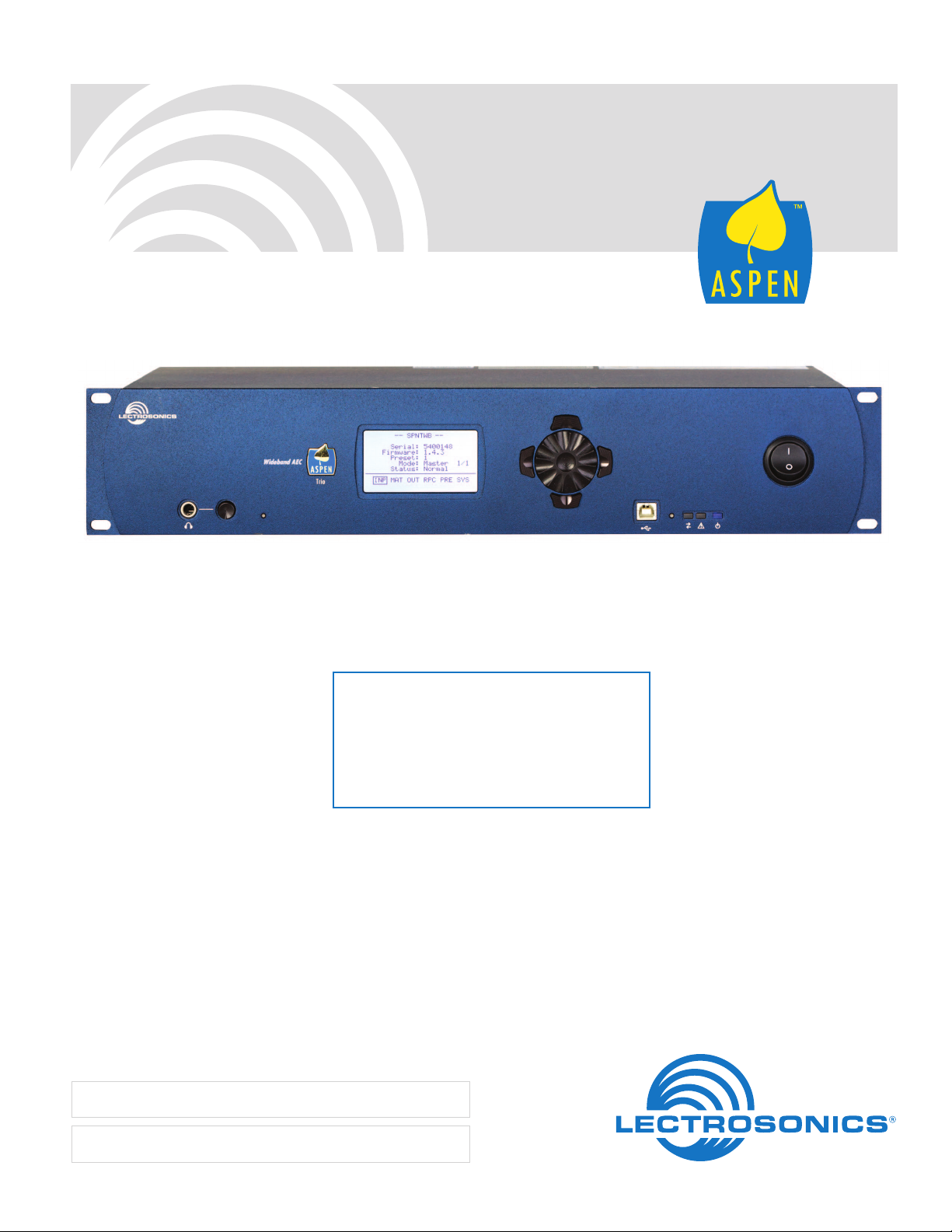
SPNTWB
Trio Conference Interface
Wideband Bridging
INSTALLATION and STARTUP GUIDE
Software and Hardware Installation and Setup
IMPORTANT
See page 14 for
Minimum Setup Requirements
Visit the ASPEN Support web site:
www.lectrosonics.com/aspensupport/
Also link from the home page: www.lectrosonics.com
Fill in for your records:
Serial Number:
Purchase Date:
Rio Rancho, NM, USA
www.lectrosonics.com
Page 2

SPNTWB
2
LECTROSONICS, INC.
Page 3

Important Safety Instructions
Installation and Startup Guide
This symbol, wherever it appears, alerts
you to the presence of uninsulated dangerous voltage inside the enclosure -- voltage
that may be sufficient to constitute a risk of
shock.
This symbol, wherever it appears, alerts
you to important operating and maintenance instructions in the accompanying
literature. Please read the manual.
When using your telephone equipment, basic safety
precautions should always be followed to reduce the
risk of fire, electric shock and injury to persons, including the following:
1) Read these instructions.
2) Keep these instructions.
3) Heed all warnings.
4) Follow all instructions.
5) Do not use this apparatus near water.
6) Clean only with a dry cloth.
7) Do not block any ventilation openings. Install in accordance with the manufacturer’s instructions.
8) Do not install near any heat sources such as radiators, heat registers, stoves, or other apparatus
(including amplifiers) that produce heat.
9) Do not defeat the safety purpose of the polarized or
grounding-type plug. A polarized plug has two blades
with one wider than the other. A grounding type plug
has two blades and third grounding prong. The wider
blade or the third prong are provided for your safety.
If the provided plug does not fit into your outlet,
consult an electrician for replacement of the obsolete
outlet.
10) Protect the power cord from being walked on or
pinched particularly at plugs, convenience receptacles, and the point where they exit from the apparatus.
11) Only use attachments/accessories specified by the
manufacturer.
12) Use only with the cart, stand, tripod,
bracket, or table specified by the
manufacturer, or sold with the apparatus. When a cart is used, use
caution when moving the cart/apparatus combination to avoid injury from
tip-over.
13) Unplug this apparatus during lightning storms or
when unused for long periods of time.
14) Refer all servicing to qualified service personnel.
Servicing is required when the apparatus has been
damaged in any way, such as power-supply cord or
plug is damaged, liquid has been spilled or objects
have fallen into the apparatus, the apparatus has
been exposed to rain or moisture, does not operate
normally, or has been dropped.
15) WARNING -- TO REDUCE THE RISK OF FIRE OR
ELECTRIC SHOCK, DO NOT EXPOSE THIS APPARATUS TO RAIN OR MOISTURE.
16) The AC mains plug, or appliance coupler shall be
readily available to the operator as a means of power
disconnection, if applicable.
17) Unit shall be connected to a MAINS socket outlet
with a protective earthing connection.
18) Do not use this product near water for example, near
a bathtub, washbowl, kitchen sink or laundry tub, in a
wet basement or near a swimming pool.
19) Avoid using a telephone (other than a cordless type)
during an electrical storm. There may be a remote
risk of electric shock from lightning.
20) Do not use the telephone to report a gas leak in the
vicinity of the leak.
21) Use only the power cord and batteries indicated in
this manual. Do not dispose of batteries in a fire.
They may explode. Check with local codes for possible special disposal instructions.
22) “CAUTION: To reduce the risk of fire, use only No.
26 AWG or larger (e.g., 24 AWG) UL Listed or CSA
Certified Telecommunication Line Cord”
SAVE THESE INSTRUCTIONS
Inspection of the Unit
Compare the packing list enclosed with the unit with the
original order. Inspect all items for damage. Immediately
call 1-800-821-1121 to report any items that are missing or damaged. The sooner you notify us, the sooner
you will get any needed replacement items shipped to
your location.
Rio Rancho, NM
3
Page 4

SPNTWB
Introduction
The SPNTWB combines the circuit board assemblies
from the SPN812 and SPNCWB in a 2RU chassis to
provide a complete, stand-alone component for telepresence and audio conferencing systems. The unit can
also be used with additional ASPEN processors to add
additional inputs and outputs. Setup and adjustments
can be made using the control panel software or the
front panel LCD interface. Inputs and outputs appearing
on the LCD have been consolidated into logical groups
to simplify navigation.
The far end audio signals in a conference participate in
the automatic mixing algorithm in same manner as local
microphones connected to the processor. Three sites
connected via two codecs and a telephone line can be
bridged into a single conference with the local site.
The ASPEN acoustic echo canceller was developed to
address the need for a single acoustic echo canceller
that could handle the challenges of multi-site bridging
and an unlimited number of microphones. The AEC
converges very quickly, then continues to increase the
cancellation depth at every opportunity as a conference
continues. Cancellation depth will increase even with
brief signal peaks from the far end, and convergence
will never be lost with any type of signal or in double talk
situations.
Signals from the far ends of the conference are routed
to the local sound system as well as serving as the
reference signal for the AEC. Audio from the local microphones (which includes far end audio from the local
loudspeakers) is routed to the AEC via a second final
mix. Far end audio present in the microphone signal mix
is cancelled, and the output of the AEC is routed back
to the far ends through the matrix.
The AEC in combination with the patented gain proportional mixing algorithm* provides outstanding audio
quality without echo heard at the far ends.
An ethernet port is provided for setup and control via
standard network connections, and an RS-232 port is
provided for use with remote control systems. The design allows simultaneous, multi-point third party control.
A two channel power amplifier is included for loudspeakers in the local sound system. The power amplifier
is driven by final mix outputs from the matrix and has a
full set of signal processing, including parametric EQ,
compressor and limiter. Class-D amplification is implemented with a late generation component that provides
exceptional efficiency, low heat and excellent audio
performance. The amplifier cannot be damaged by wiring errors.
4
LECTROSONICS, INC.
Page 5

Installation and Startup Guide
Table of Contents
IMPORTANT ............................................................................1
Important Safety Instructions...............................................3
Inspection of the Unit ............................................................3
Introduction ............................................................................4
Front Panel .............................................................................6
Rear Panel ..............................................................................7
Hardware Installation ............................................................8
Installing the chassis into a rack ..........................................8
Cables .................................................................................8
Audio Connectors ...............................................................8
Audio Inputs – Unbalanced ..................................................8
Audio Outputs ......................................................................9
Programmable Inputs ...........................................................9
Programmable Outputs ........................................................9
Power Amp Outputs .............................................................9
ASPEN RS-232 Port Wiring Diagram ................................10
Crestron® and AMX® Port Wiring Diagram .........................10
Cabling Of Stacked Units ...................................................10
Software Installation ...........................................................11
Refer to the Help Files .........................................................11
Creating an ASPEN Installer Disk ......................................11
Software and Firmware Updates ........................................12
Firmware Update Procedure ...............................................12
Update Procedure ..............................................................12
MCU Recovery from Interrupted Firmware Update ...........13
Stacking Multiple Units .......................................................14
Using the Control Panel ......................................................14
Minimum Setup ....................................................................14
The Signal Flow Screen ......................................................16
Using the LCD ......................................................................18
LCD Categories and Settings .............................................20
Network Setup .....................................................................21
Web Browser Interface ........................................................21
Service and Repair ..............................................................22
Returning Units for Repair .................................................22
FCC PART 68 COMPLIANCE INFORMATION .....................23
INDUSTRY CANADA NOTICE .............................................23
Rio Rancho, NM
5
Page 6
SPNTWB
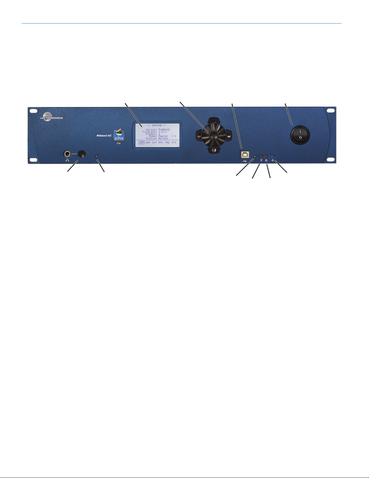
Front Panel
The SPNTWB includes a front panel LCD and rotary
style navigation control for adjustment without the need
for a computer interface. The headphone output is used
to monitor each final mix for diagnostics and system
checkout.
Blue LEDs on the right side of the front panel indicate
power status and communications through USB, serial
and ethernet ports. The center white LED blinks to indicate an error, and glows during firmware updates.
LCD
Headphone Monitor
MCU Recovery
recessed pushbutton
Headphone Monitor
Used to monitor individual final mix buses as selected
on the LCD. Standard 1/4 inch jack and level control.
Drives both channels of stereo headphones.
MCU Recovery (recessed pushbutton)
Used in the procedure to recover from an interrupted
firmware update procedure. See section on Firmware
Update Procedure for details on usage.
Navigation/Select
Control
Firmware Update
recessed pushbutton
USB Port
Standard USB connector for the setup and control of
an SPNTWB from a Windows® XP, Vista or 7 computer
system* with USB interface.
Firmware Update (recessed pushbutton)
Used in the procedure to update the firmware in the
processor. See the section on Firmware Update Pro-
cedure for details.
USB Port
Comm
LED
POWER Switch
Power LED
Alert
LED
LCD
Allows setup and adjustment of most operating parameters and for minor adjustments without a computer
interface.
Navigation/Select Control
Used to navigate menus and make value selections and
settings on the LCD.
*Windows is a registered trademark of Microsoft Corp.
Status LEDs
• CommLED-blinkstoindicateUSB,RS-232and
ethernet communication
• AlertLED-blinkstoindicatefaultorerror
• AlertLED-glowswhiteduringrmwareupdates
• PowerLED-glowstoindicatepowerON
6
LECTROSONICS, INC.
Page 7
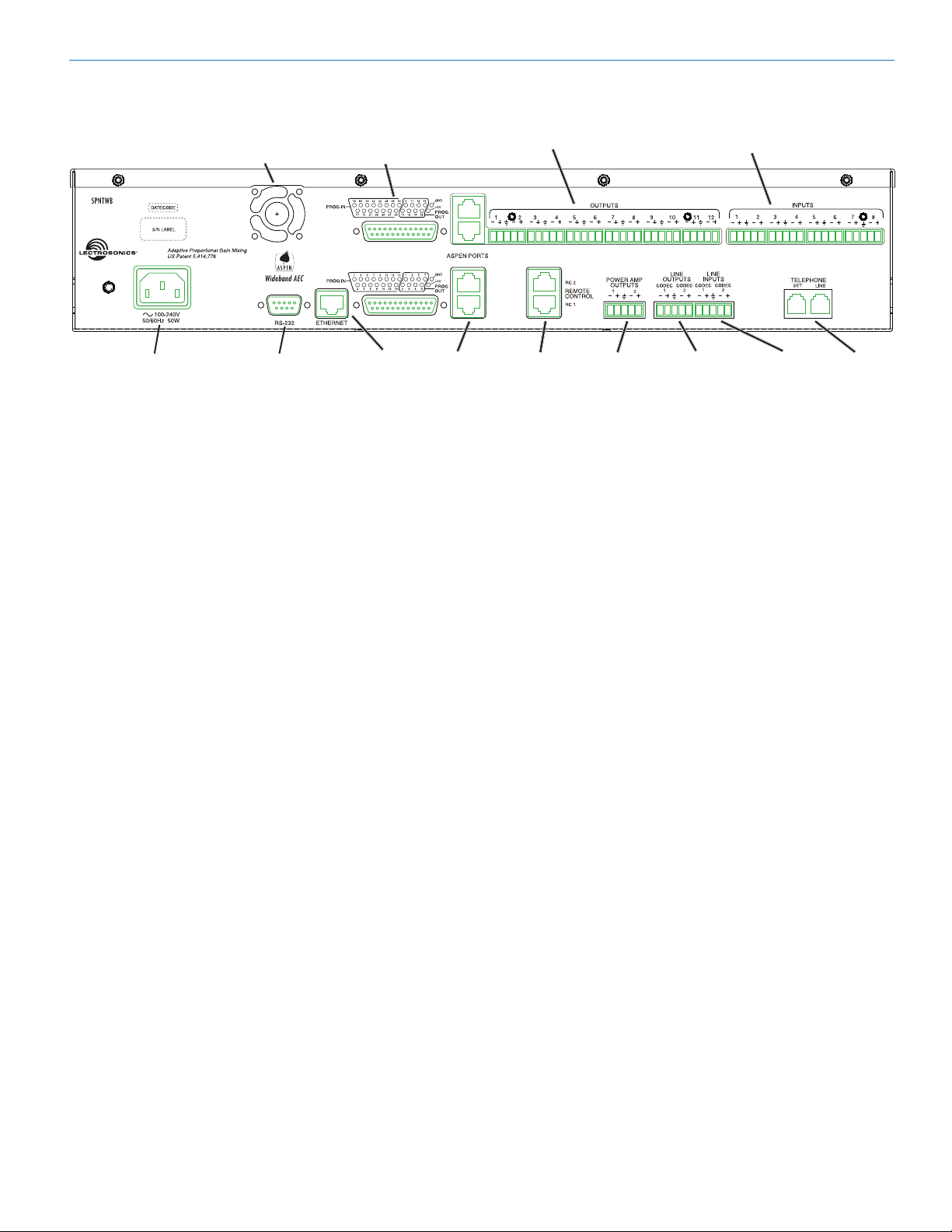
Rear Panel
Installation and Startup Guide
Cooling Fan
Outlet
Power Inlet RS232
Serial Port
Programmable Input
and Output Ports
Ethernet
Port
Power Inlet
The switching power supply will operate with line voltages between 100 and 240 VAC. The inlet socket is a
standard 3-pin C14 type that accepts any cordset with a
C13 connector.
Cooling Fan
The microprocessor monitors the internal temperature
of the processor and controls the variable speed fan as
needed. Operating temperature is very well regulated.
RS-232 and Ethernet Ports
Each host assembly provides RS-232 and Ethernet
ports for communication with the microprocessor. The
ports can be utilized simultaneously for monitoring,
setup and control.
ASPEN Ports
This gigabit bus transports audio and data from one
board to the next through CAT-6 cabling and RJ-45 connectors. Processors are normally installed with the Master unit on top and Slave units below it. The cabling is
then connected from the uppermost jack on one board
to the lowermost jack on the unit just above it. See page
9 for more information.
Balanced Mic/Line Inputs
Every mic/line input is a balanced, differential type with
adjustable gain from -10 to +60 dB. Connectors are a
standard 5-pin Phoenix depluggable type with adjacent
channels sharing a common ground.
Data/Audio
Bus Ports
Balanced Outputs Balanced Inputs
Made In the USA
Remote
Control
Power Amp
Outputs
Line Outputs
(Codecs)
Line Inputs
(Codecs)
Telephone
Set/Line
Balanced Outputs
All outputs are a balanced, differential type. Channels 1
through 8 on each board are nominal line level outputs
with gain adjustment from -60 to +20 dB. Channels 9
through 12 on each board are also line level outputs
with switchable attenuation of -20 and -40 dBu nominal
levels (mic level), with gain adjustment from OFF to +20
dB.
Programmable Input and Output Ports
Programmable inputs and outputs used to control
levels, settings, indicate the current state of a programmable input and control a variety of other parameters.
ASPEN Bus Data/Audio Ports
These RJ-45 jacks carry the audio signals and control data between each system board as well as units
stacked together.
Remote Control
These RJ-45 jacks provide interfaces for RCWTH4
remote control units. Each jack is assignable to CODEC
1 or 2, or to the telephone line.
Conferencing Inputs and Outputs (Codecs)
Analog audio input and output connectors for the Codec
ports.
Telephone Set/Line
RJ11 jacks for connecting a standard telephone line
and a single-line telephone set.
Rio Rancho, NM
Power Amp Outputs
The amplifier is designed to run continuously (idle or
with a load) without heat buildup, making it ideal for
permanent installations where prolonged operation is
required.
7
Page 8
SPNTWB
Processor
Balanced source to
ASPEN input
Source
Shield
Hardware Installation
Installing the chassis into a rack
Install the chassis so that the cooling fan vent is not
blocked. Mount with 4 rack screws using the appropriate mounting holes. Use nylon washers to prevent
damage to the front panel’s finish when tightening the
mounting screws.
All ASPEN processors have internal switching power
supplies that can tolerate voltages ranging from 100
to 240 VAC. Use an approved power cord with an IEC
60320 C13 connector.
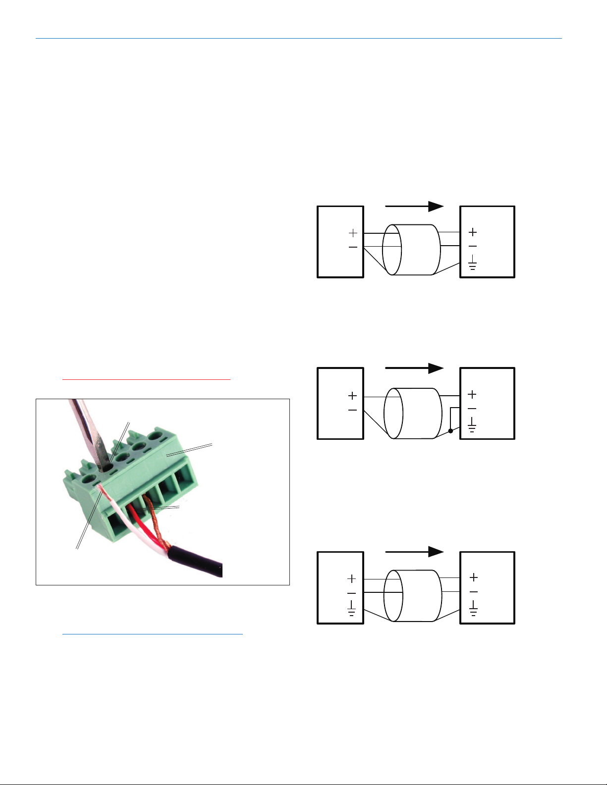
Cables
It is recommended to use lacing bars for cable strain
relief when mounting in a rack. Use only professional
audio cable with proper shielding – typically, two conductor plus ground/shield.
Audio Connectors
The analog audio inputs and outputs are connected
through 5 pin de-pluggable connectors. Strip the insulation back 1/8 to 3/16” but do not tin (apply solder to)
the leads. Insert the wire into a de-pluggable connector, leaving less than 1 mm of bare wire exposed, then
tighten the retaining screw.
Audio Inputs – Unbalanced
Unbalanced audio sources include items such as
consumer VCR’s, DVD players, etc., which can be connected with either two wire or three wire cables. The (+)
terminal of the source is connected to the (+) terminal
of the processor. The shield and (–) connections are
made as shown here.
Three wire cables should have the shield connected to
the (–) connector at the source end of the cable.
Source
Unbalanced source to
ASPEN input – 3-wire cable
Two wire cables should have a jumper between the
processor (–) input and ground.
Shield
Processor
Caution: Do not overtighten the screws.
Retaining Screw
(Do not overtighten)
5-pin depluggable
connector
Do not leave more than
1 mm of exposed wire
beyond the connector.
Do not apply
solder to leads
Note the labeling on the rear panel for the positive and
negative leads. Ground is shared between two connections (the center pin).
Note: ASPEN processors do not have a “pin 1
problem.” Inputs and outputs are true differential
connections.
Source
Shield
Processor
Unbalanced source to
ASPEN input – 2-wire cable
Audio Inputs – Balanced
Balanced audio sources connect to the processor inputs in a straight “pin to pin” configuration.
8
LECTROSONICS, INC.
Page 9

Installation and Startup Guide
10K Linear Potentiometer
CCW
CW
+5V
To Programmable Input Pin
Gnd
Contact Closure as Programmable Input
To Programmable Input Pin
Gnd
DC Voltage Source as Programmable Input
To Programmable Input Pin
0VDC (Off) to +5VDC (On)
Gnd
Potentiometer Connection for
Analog Control of Gain
+
Audio Outputs
The line outputs are a balanced differential configuration which can drive balanced or unbalanced inputs on
other audio equipment with the wiring shown here.
Balanced output to a balanced input is a straightforward
“pin to pin” configuration.
Shield
Output
Destination
Balanced output to
balanced destination
Balanced output to unbalanced input with a 3-wire
cable is connected with the cable shield added to the
(–) terminal on the destination input.
Shield
Output
Destination
Balanced output to unbalanced
destination – 3-wire cable
Balanced output to unbalanced input with a 2-wire cable
is connected with the output (–) connected to the cable
shield at the processor output.
Programmable Inputs
Programmable inputs are provided to enable external
control over a variety of parameters. Each input can
respond to a contact closure, a DC voltage source, or
the variable voltage output from a potentiometer. The
following illustrates common connections to the programmable input pins.
Programmable
Inputs
Programmable
Outputs
Ground
+5VDC
Output
Shield
Balanced output to unbalanced
destination – 2-wire cable
Power Amp Outputs
Each output can drive a
variety of loads, including
loudspeakers, long cable
runs and headphones.
The BTL (bridge tied load)
configuration allows the
two channels to be wired
in parallel on a common
load to double the output
power.
Rio Rancho, NM
-
+
Destination
Programmable Outputs
Programmable outputs are used for several purposes:
• indicatethecurrentstateofaprogrammableinput
• monitoractivityontelephoneorcodecinterfaces
• monitoractivepresetchanges
Each programmable output is the electrical equivalent
of a contact closure to ground. When a programmable
output is “active,” it conducts current to ground. When
the programmable output is “inactive,” no current flows
to ground. The maximum usable voltage for the programmable outputs is 40 V and they will safely conduct
up to 100 mA DC continuous.
Both LEDs and 5V relay coils can be powered by the
+5 V DC pins on the programmable input connector, as
long as the maximum combined current for all LEDS
and relay coils does not exceed 100 mA.
9
Page 10

SPNTWB
380 Ohms
Pro gr amma b le Output Pi n
380 Ohms
Programmable Output Pin
1N4001
or equi v .
Exte r na l
DC V oltag e
Source
(<40VDC)
Rel a y Coi l
Coil current <100mA
Pro gr amma b le Output Pi n
Relay is on when the programmable output is active
+5VDC
+5VDC
GND
LED is ON when the programmable output is active
GND
LED is OFF when the programmable output is active
LED
380 TO
500 OHM
10K
LINEAR
POT
CW
CCW
IN 1
IN 3
ON
OFF
LOGIC OUTPUTS
GROUND
5VDC
LOGIC INPUTS
LOGIC
OUT 7
LOGIC IN 3
ANODE CATHODE
V
R
Anode
Cathode
CathodeAnode
Wiring Diagram
1
1
Crestron® and AMX® Port Wiring Diagram
Note: The diagram above shows an external DC source powering the relay coil. This is necessary whenever coil voltages
exceed 5 volts.
2
RX
3
TX
4
5
GND
6
7
8
9
Female
connector
Crestron
RS-232
Port
Male jack
ASPEN
RS-232
Port
Female jack
TX
RX
GND
2
3
4
5
6
7
8
9
Male
connector
Wiring Diagram
Cabling Of Stacked Units
In a stacked configuration, ASPEN processors must
be interconnected as shown here. Each Slave unit in
a stack gathers data and audio signals from the unit
below it, adds its own signals and passes the total on to
the unit above it. At the top of the stack, the Master unit
gathers all signals from below, adds its own and then
sends the total back down the bus to all Slave units
below it. In this manner, all Slave units have access to
all inputs on any unit in the stack.
Each circuit board has an upper and a lower CAT-5 connector. Since there are two circuit boards in a 2RU unit,
the circuit boards are connected in the same manner as
if they were in separate chassis. The ASPEN bus is bidirectional, handling data and audio signal forward and
back propagation through a single cable connection.
ASPEN RS-232 Port Wiring Diagram
ASPEN Device to PC
1
2
TX
3
ASPEN
RS-232
Port
DCE pin
functions
Female
jack
10
RX
GND
connector
4
5
6
7
8
9
Male
Female
connector
1RU SPN
Processor
configured as
Master
ASPEN PORT
2RU SPN
Processor
1
DCD
2
RX
3
TX
DTR
GND
DSR
RTS
CTS
RI
Host
Serial
Port
(PC)
DTE pin
functions
4
5
6
7
8
9
configured as
intermediate
Slave
1RU SPN
Processor
configured
as lowermost
Slave
Male jack
The processors automatically configure themselves for
Master and Slave status as determined by the cabling.
If a unit is connected to another unit above it through
the upper connector, it is automatically configured as
a Slave. If there is no unit above it, then it becomes a
Master.
LECTROSONICS, INC.
Page 11

Software Installation
Installation and Startup Guide
NOTE: Uninstall any previous version before
installing the software.
ASPEN Control Panel software can be installed from
the disk supplied with each processor, or from files
downloaded from the ASPEN Support web site.
http://www.lectrosonics.com/aspensupport
Installation is straightforward and requires no special
instructions.
The downloaded ASPEN Control Panel Installer will
automatically install the USB driver, GUI and Help files.
The disk supplied with the processor has separate
installers. Make sure you have at least the USB driver
and control panel GUI installed.
The Welcome screen appears first with a brief message
about closing other programs before installing. Click
Next to continue.
The third screen displays an option to select the desired
installation. It is best to check all three boxes so the
the USB driver, Control Panel and Help utility will all be
installed.
Follow the on-screen prompts to complete the installation. On the last screen, click Finish to exit the installer.
Refer to the Help Files
Once the processors are installed, configured and communicating with a computer system, refer to the Help
files in the software ASPEN Control Panel program for
additional information regarding the available settings,
adjustments and control.
The next screen displays the License Agreement.
Click on I Agree to continue.
Creating an ASPEN
Installer Disk
If you do not have the disk supplied with the processor,
go to the web site and download the ASPEN Installation
Disk .iso file.
http://www.lectrosonics.com/aspensupport/index.php/
installation-disk
Save the file to your local drive in a familiar location.
Open a disk copier utility such as Roxio Classic and
select the operation to Burn from a Disk Image File.
NOTE: The .iso file cannot be simply copied to the
disk. The disk recording utility must run a process
that creates a disk from a stored image file.
The .iso file format is recognized by almost any disk
creation software.
Rio Rancho, NM
11
Page 12

SPNTWB
Software and Firmware
Updates
On ASPEN models with a front panel LCD, the firmware
version is displayed on the Main menu screen.
For all ASPEN models, the firmware version is displayed in the Control Panel program when connected to
the processor.
Firmware
version
Firmware version
Firmware Update
Procedure
Update Procedure
1) It is assumed that the USB drivers and ASPEN control panel software have been installed. If not, go the the
web site and download the Control Panel Installer and
follow the instructions to install the USB driver, GUI and
Help file.
http://www.lectrosonics.com/aspensupport/index.php/
control-panel-software
2) Launch the Control Panel program. After the panel
opens, click on Connect->Update Firmware... The
Update Wizard will open, with instructions on connecting and configuring the processor.
Obtaining Updates
The latest versions of software and firmware can be
downloaded from the ASPEN support site:
http://www.lectrosonics.com/aspensupport
ASPEN Control Panel Updates:
Open the Control Panel program and choose Help>Check for Updates... from the Main menu. If and
update is available, it will be downloaded and installed
automatically.
Firmware Updates:
Downloaded files arrive in a single .zip file with the
model number and version indicated by the filename.
Extract the file to a folder on your local drive. The resulting filename will indicate the model number and version, followed by the extension “.update.”
3) On the processor, hold the Firmware Update pushbutton switch in with a pen or paper clip and turn on
the power to the processor. The unit will boot into the
firmware update mode and the white Alert LED on the
processor front panel will glow.
Firmware Update
pushbutton
4) Connect the processor to the computer with the USB
cable.
White Alert LED
12
LECTROSONICS, INC.
Page 13

Installation and Startup Guide
5) Click on Next in the control panel and another page
will open, allowing you to select the device to be updated. Highlight the device and click Next to proceed.
6) The next page allows you to select the update file.
Use the “Browse” button to point at the firmware update
file and click Next to continue.
8) Do not disturb the USB cable connection during the
update process. The firmware update takes up to 15
minutes to complete. Be sure the computer does not
go into hibernation or sleep mode during the update
process.
NOTE: If the procedure is interrupted, see the
next section on recovery
9) When the update is complete, click Finish to exit the
Update Wizard.
10) Cycle the power on the processor to restart using
the updated firmware.
MCU Recovery from Interrupted Firmware
Update Procedure
If instructed to do so by Lectrosonics Customer Support, the firmware in a non-functioning unit can be
restored.
Launch the Control Panel program. After the panel
opens, click on Connect->Update Firmware...
In the lower part of the screen is a check box that is
used only for the recovery process. When the box is
checked, the instructions will change to describe the
recovery procedure.
Browse button
7) Review the information displayed and click on Start
Update.
Recovery check box
Follow the on-screen prompts to return the unit to normal operation.
Rio Rancho, NM
13
Page 14

SPNTWB
Stacking Multiple Units
If Slave units are not powered up when the Master unit
boots up, the Slave may not be detected for several
minutes. It is good practice to turn all units on simultaneously or turn on Slave units before turning on the
Master unit.
The available processors will appear in a “stack” in the
control panel. The Master unit details will appear at the
top, with Slave units below it appearing in the order that
they are connected with the cable connections to the
ASPEN port jacks.
The Master
unit connected
directly
The Master
and Slaves
connected
below it
Click OK to
open the control
panels
Minimum Setup
A required minimum setup is needed to allow the
processor to pass signals and provide acoustic echo
cancellation:
• DenetheInputsandadjustgain
• DenetheCrosspoints
• Denethemixestobeusedassignalsourcesforthe
outputs
• DenetheOutputsandadjustlevels
• ConguretheConferencingConnections
Inputs
Click on the Inputs tab. The setup screen provides controls for gain, signal polarity (phase) and muting, with
level indicators. Connect signal sources and adjust the
gain as needed.
Input gain slider
Input signal level
Refer to the cabling diagram for the ASPEN ports in the
section entitled Hardware Installation.
Using the Control Panel
To connect to connect a running ASPEN device, choose
a connection method from the Connect menu: USB,
Network or Serial. The device can be configured directly when connected.
USB, Network or Serial
To work on a system design project, choose an option
from the Project menu. You may create a new project or
open an existing project.
Choose Help->ASPEN Online Help... to open an
extensive Help system describing the may features and
functions of the Control Panel program.
Input gain value
Inputs screen
Crosspoints
Click on the Mix Matrix tab. Inputs are assigned to
crosspoints which provide the signal sources for the
outputs.
Mix Matrix screen
14
LECTROSONICS, INC.
Page 15

Installation and Startup Guide
Output Sources
Click on the Output Source tab. These assignments
pass the matrix mixes to the outputs.
Pull down menu for
mix assignment
Output Source screen
Outputs
Click on the Outputs tab. This allows adjustment of
the gain and muting of each output. Level metering is
provided for accurate setup.
Acoustic Echo Canceller
Click on the Acoustic Echo Canceller tab at the bottom of the conferencing screen. The AEC (acoustic
echo canceller) can be enabled on any or all of the
conference interfaces. Strip chart metering indicates the
performance of the AEC on each interface.
Select the desired interface to display, or to display all
four simultaneously.
Select display of individual
or all interface screens
Conferencing screen (AEC setup selected)
Outputs screen
Conference Connections
Click on the Conferencing tab. Conferencing settings
define the behavior of the Codec and Telephone interfaces.
Select Telephone, CODEC and
AEC setup screens
Conferencing screen (Telephone Interface setup selected)
Rio Rancho, NM
15
Page 16

SPNTWB
The Signal Flow Screen
Select the Signal Flow tab. This comprehensive, intuitive interface allows settings to be made through the
entire signal chain. Double left click and single right
click actions open setup and status dialogue boxes.
The view may be panned or zoomed as needed. Hold
down the CTRL key and press + to zoom in. Hold
down the CTRL key and press - to zoom out. The
mouse scroll wheel can also be used. Hold down the
CTRL key and turn the mouse wheel up or down to
zoom in or out.
16
LECTROSONICS, INC.
Page 17

Unused crosspoint columns can be hidden and unhidden by highlighting a range of Mixes across the top,
followed by a right click and selection of the desired
state.
Installation and Startup Guide
Rio Rancho, NM
17
Page 18

SPNTWB
Using the LCD
The LCD can be used to check current settings or make
adjustments without using a computer interface.
Boot Screen
Main Window
The LCD will
show the mode,
the position and
total number
of units in the
stack.
Shown here is
the Master as
unit 1 of 2.
Shortcut Buttons
• LCDBacklightToggle:Press both the LEFT and
RIGHT buttons to turn the backlight on and off.
• EmergencyMute(panicbutton):Pressing the UP
and DOWN buttons together will mute all outputs to
remedy situations such as runaway feedback.
• RestoreDefaultSettings(MasterReset):Hold in
the LEFT and UP buttons while turning on the power
to restore the factory default settings. The Alert LED
will glow white during the process, which takes about
75 seconds to complete.
Panel Lock/Unlock
From the Main Window, use the rotary control to select
SYS in the lower row window and press the center
switch. Then scroll down with the rotary control to the
menu item named Front Panel Lock and press the cen-
ter switch to enter the setup screen.
Navigation Control
The navigation control for the LCD consists of a rotary
control and four directional buttons for selection of
menu items and to enter values. The four outer buttons
are referenced as LEFT, RIGHT, UP and DOWN. Pressing the center of the rotary control provides a “select” or
“center switch” function.
Center Switch
Press both Left and Right buttons to
turn the LCD backlight OFF and ON
The LEFT functions as a BACK button to return to the
previous menu from setup screens as prompted by the
symbol in the lower left corner of the LCD.
Select the Unlocked/Locked item with the rotary control,
press the center switch.
A prompt will appear asking you to enter the passcode.
The factory default passcode is five presses of the center switch. Once the correct passcode is entered, the
panel will allow access to the screen items to change
the unlocked/locked status, enter a new passcode and
save the results.
The passcode can consist of any combination of five
successive button presses of the four outer switches
and the center switch such as: LEFT > RIGHT > UP >
DOWN > CENTER.
18
LECTROSONICS, INC.
Page 19

Installation and Startup Guide
After selecting the mode and/or changing the passcode,
select SAVE with the rotary control and press the center
switch to save the settings.
A progress bar
will appear as the
settings are saved.
Press the LEFT (9:00 o’clock) button to return to the
previous screen.
Master Reset
Hold the LEFT and UP buttons in at power up to restore
factory default settings.
Navigating Individual Settings
The following example illustrates the structure of the
LCD screens used to set up the processor.
Select a category from the Main Screen.
A submenu will provide a list of the specific adjustments
that can be made in that category. Rotate the scroll
wheel to highlight the desired setting and press the
center switch to select it.
WARNING: Master Reset will remove all stored
settings, unlock the control panel and reset the
passcode to five center button presses.
Master Reset takes about 75 seconds to complete
while the Alert LED on the front panel glows white.
The display will then return to the Main Window and
the power LED will light up to indicate power ON and a
“ready” status.
EXAMPLE: Mic/Line Input Setup accesses a setup
screen where gain values, muting, phantom power,
polarity (phase) and delay can be adjusted.
Highlight the desired item and press the center switch
to enter the value for this setting. Press the center
switch to store the new setting (item highlight is removed) before selecting another item or returning to the
previous menu.
NOTE: Press the center switch to store the value
(highlight is removed) before navigating to a
different item or menu.
Rio Rancho, NM
19
Page 20

SPNTWB
LCD Categories and
Settings
INP (Input)
• InputLevels
• Mic/LineInputSetup
• ConferenceInputSetup
• TestSigInputSetup
• CompressorSetup
• NoiseReductionSetup
• ADFEFilterSetup
• EQFilterSetup
• InputGroupSetup
MAT (Matrix)
• CrosspointGain
• CrosspointMute
• CrosspointMixMode
• CrosspointInvert
OUT (Output)
• OutputLevels(alevelmeterdisplayonly)
• OutputSetup(entergain,mutinganddelay;includes
attenuation value display)
• ConferenceOutputSetup
• OutputSource
• CompressorSetup
• LimiterSetup
• EQFilterSetup
• OutputGroupSetup
PRE (Presets)
• RecallSettings
• StoreSettings
• ResettoDefaults
• RunonRecallMacro
• PowerupDefaults
• ProtectedSettings
SYS (System)
• ConferencingSetup
Telephone Interface
DTMF and Dialing
Codec 1 Interface
Codec 2 Interface
AEC Configuratrion
AEC Status
Remote Control Ports
• HeadphoneMonitor
• CommandView
• NetworkSettings
• RS232Settings
• SetTime
• SetDate
• TimerSetup
• AlarmSetup
• EventSetup
• TestSignalControl
• RunMacro
• Run-On-PowerupMacro
• FrontPanelLock
RPC (Rear Panel Control)
• ProgInputSetup
• VirtProgInputSetup(slaveunittriggersfromProg
Input activity on Master unit)
• ProgOutputSetup
• RPInputGainSetup
• RPOutputGainSetup
• RPCrosspointGain
• InputChActivity
20
LECTROSONICS, INC.
Page 21

Installation and Startup Guide
Network Setup
The SPNTWB is IP addressable over an ordinary Ethernet network. The use of DHCP to configure the network
interface is recommended for easy setup.
Using the front panel LCD, navigate to SYS>Network
Settings and set Use DHCP to YES.
Web Browser Interface
A simple interface is provided to communicate directly
with the processor through a network using the HTTP
port and a standard browser. This interface provides
access to the processor in the same manner as the
Command Terminal interface in the software.
Launch your browser and enter the IP addresses assigned to the processor in the top window.
When the processor is connected a summary screen
will appear to verify the connection. Click on the link to
enter the dialogue screen.
Connect the processor into the network and cycle the
power. The processor will boot up and the DHCP server
will assign an IP address. The address can be viewed in
the Network Settings display.
IP address will
appear here.
NOTE: Changes to the network settings do not
take effect until the processor power is cycled off
and back on again.
Rio Rancho, NM
Click on the link to enter
the dialogue screen
Enter ASPEN commands and view the replies to verify
the processor setup or to make adjustments.
Enter Commands here
View Replies here
21
Page 22

SPNTWB
Service and Repair
If your system malfunctions, you should attempt to correct or isolate the trouble before concluding that the equipment
needs repair. Make sure you have followed the setup procedure and operating instructions. Check the interconnecting cables and then go through the Troubleshooting section in this manual.
We strongly recommend that you do not try to repair the equipment yourself and do not have the local repair shop
attempt anything other than the simplest repair. If the repair is more complicated than a broken wire or loose connection, send the unit to the factory for repair and service. Don’t attempt to adjust any controls inside the units. Once
set at the factory, the various controls and trimmers do not drift with age or vibration and never require readjustment.
There are no adjustments inside that will make a malfunctioning unit start working.
LECTROSONICS’ Service Department is equipped and staffed to quickly repair your equipment. In warranty repairs
are made at no charge in accordance with the terms of the warranty. Out-of-warranty repairs are charged at a modest
flat rate plus parts and shipping. Since it takes almost as much time and effort to determine what is wrong as it does
to make the repair, there is a charge for an exact quotation. We will be happy to quote approximate charges by phone
for out-of-warranty repairs.
Returning Units for Repair
For timely service, please follow the steps below:
A. DO NOT return equipment to the factory for repair without first contacting us by e-mail or by phone. We need to
know the nature of the problem, the model number and the serial number of the equipment. We also need a phone
number where you can be reached 8 A.M. to 4 P.M. (U.S. Mountain Standard Time).
B. After receiving your request, we will issue you a return authorization number (R.A.). This number will help speed
your repair through our receiving and repair departments. The return authorization number must be clearly shown
on the outside of the shipping container.
C. Pack the equipment carefully and ship to us, shipping costs prepaid. If necessary, we can provide you with the
proper packing materials. UPS or FEDEX is usually the best way to ship the units. Heavy units should be “doubleboxed” for safe transport.
D. We also strongly recommend that you insure the equipment, since we cannot be responsible for loss of or damage
to equipment that you ship. Of course, we insure the equipment when we ship it back to you.
Lectrosonics USA:
Mailing address: Shipping address: Telephone:
Lectrosonics, Inc. Lectrosonics, Inc. (505) 892-4501
PO Box 15900 581 Laser Rd. (800) 821-1121 Toll-free
Rio Rancho, NM 87174 Rio Rancho, NM 87124 (505) 892-6243 Fax
USA USA
Web: E-mail:
www.lectrosonics.com sales@lectrosonics.com
Lectrosonics Canada:
Mailing Address: Telephone: E-mail:
49 Spadina Avenue, (416) 596-2202 Sales: colinb@lectrosonics.com
Suite 303A (877) 753-2876 Toll-free Service: joeb@lectrosonics.com
Toronto, Ontario M5V 2J1 (877-7LECTRO)
(416) 596-6648 Fax
22
LECTROSONICS, INC.
Page 23

Installation and Startup Guide
FCC PART 15 COMPLIANCE INFORMATION
This equipment has been tested and found to comply with the limits for a Class A digital device, pursuant to Part 15
of the FCC Rules. These limits are designed to provide reasonable protection against harmful interference when the
equipment is operated in a commercial environment. This equipment generates, uses, and can radiate radio frequency
energy and, if not installed and used in accordance with the instruction manual, may cause harmful interference to
radio communications. Operation of this equipment in a residential area is likely to cause harmful interference in which
case the user will be required to correct the interference at his own expense
FCC PART 68 COMPLIANCE INFORMATION
This equipment complies with Part 68 of the FCC rules. Located on the equipment is a label that contains, among
other information, the ACTA registration number and ringer equivalence number (REN.) If requested, this information
must be provided to the telephone company.
The REN is used to determine the quantity of devices which may be connected to the telephone line. Excessive
REN’s on the telephone line may result in the devices not ringing in response to an incoming call. In most, but not all
areas, the sum of the REN’s should not exceed five (5.0). To be certain of the number of devices that may be connected to the line, as determined by the total REN’s contact the telephone company to determine the maximum REN
for the calling area.
This equipment cannot be used on the telephone company-provided coin service. Connection to Party Line Service is
subject to State Tariffs.
If this equipment causes harm to the telephone network, the telephone company will notify you in advance that temporary discontinuance of service may be required. If advance notice isn’t practical, the telephone company will notify the
customer as soon as possible. Also, you will be advised of your right the file a complaint with the FCC if you believe it
is necessary.
The telephone company may make changes in its facilities, equipment, operations, or procedures that could affect the
operation of the equipment. If this happens, the telephone company will provide advance notice in order for you to
make the necessary modifications in order to maintain uninterrupted service.
If trouble is experienced with this equipment, please contact:
Lectrosonics, Inc.
581 Laser Rd. Rio Rancho, NM 87124
Tel: 505-892-4501
Fax: 505-892-6243
If the trouble is causing harm to the telephone network, the telephone company may request you to remove the equipment from the network until the problem is resolved.
This equipment uses the following USOC jacks: RJ11C
It is recommended that the customer install an AC surge arrester in the AC outlet to which this device is connected.
This is to avoid damaging the equipment caused by local lightening strikes and other electrical surges.
INDUSTRY CANADA NOTICE
This product meets the applicable Industry Canada technical specifications/Le présent materiel est conforme aux
specifications techniques applicables d’Industrie Canada.
The Ringer Equivalence Number is an indication of the maximum number of devices allowed to be connected to a
telephone interface.
The termination on an interface may consist of any combination of devices subject only to the requirement that the
sum of the RENs of all the devices does not exceed five.
L’indice d’équivalence de la sonnerie (IES) sert à indiquer le nombre maximal de terminaux qui peuvent être raccordés à une interface téléphonique.
La terminaison d’une interface peut consister en une combinaison quelconque de dispositifs, à la seule condition que
la somme d’indices d’équivalence de la sonnerie de tous les dispositifs n’excède pas 5.”
Rio Rancho, NM
23
Page 24

581 Laser Road NE • Rio Rancho, NM 87124 USA • www.lectrosonics.com
(505) 892-4501 • (800) 821-1121 • fax (505) 892-6243 • sales@lectrosonics.com
LIMITED THREE YEAR WARRANTY
The equipment is warranted for three years from date of purchase against defects in
materials or workmanship provided it was purchased from an authorized dealer. This
warranty does not cover equipment which has been abused or damaged by careless
handling or shipping. This warranty does not apply to used or demonstrator equipment.
Should any defect develop, Lectrosonics, Inc. will, at our option, repair or replace any
defective parts without charge for either parts or labor. If Lectrosonics, Inc. cannot
correct the defect in your equipment, it will be replaced at no charge with a similar new
item. Lectrosonics, Inc. will pay for the cost of returning your equipment to you.
This warranty applies only to items returned to Lectrosonics, Inc. or an authorized
dealer, shipping costs prepaid, within three years from the date of purchase.
This Limited Warranty is governed by the laws of the State of New Mexico. It states the
entire liablility of Lectrosonics Inc. and the entire remedy of the purchaser for any
breach of warranty as outlined above. NEITHER LECTROSONICS, INC. NOR
ANYONE INVOLVED IN THE PRODUCTION OR DELIVERY OF THE EQUIPMENT
SHALL BE LIABLE FOR ANY INDIRECT, SPECIAL, PUNITIVE, CONSEQUENTIAL,
OR INCIDENTAL DAMAGES ARISING OUT OF THE USE OR INABILITY TO USE
THIS EQUIPMENT EVEN IF LECTROSONICS, INC. HAS BEEN ADVISED OF THE
POSSIBILITY OF SUCH DAMAGES. IN NO EVENT SHALL THE LIABILITY OF
LECTROSONICS, INC. EXCEED THE PURCHASE PRICE OF ANY DEFECTIVE
EQUIPMENT.
This warranty gives you specific legal rights. You may have additional legal rights which
vary from state to state.
5 November 2013
 Loading...