

Page 1

SPNDNT
Network Processor
IMPORTANT NOTICE:
INSTALLATION AND STARTUP GUIDE
Several settings are mandatory to ensure the
processor will connect and operate properly
with a network and other processors.
See page 11 for details.
A trademark of Audinate Pty Ltd.
Fill in for your records:
Serial Number:
Purchase Date:
Rio Rancho, NM, USA
www.lectrosonics.com
Page 2

ASPEN Digital Processor
2
LECTROSONICS, INC.
Page 3

Important Safety Instructions
Installation and Quick Start Guide
This symbol, wherever it appears, alerts
you to the presence of uninsulated dangerous voltage inside the enclosure -- voltage
that may be sufficient to constitute a risk of
shock.
This symbol, wherever it appears, alerts
you to important operating and maintenance instructions in the accompanying
literature. Please read the manual.
When using your telephone equipment, basic safety
precautions should always be followed to reduce the
risk of fire, electrick shock and injury to persons, including the following:
1) Read these instructions.
2) Keep these instructions.
3) Heed all warnings.
4) Follow all instructions.
5) Do not use this apparatus near water.
6) Clean only with a dry cloth.
7) Do not block any ventilation openings. Install in accordance with the manufacturer’s instructions.
8) Do not install near any heat sources such as radiators, heat registers, stoves, or other apparatus
(including amplifiers) that produce heat.
9) Do not defeat the safety purpose of the polarized
or grounding-type plug. A polarized plug has two
blades with one wider than the other. A grounding
type plug has two blades and third grounding prong.
The wider blade or the third prong are provided
for your safety. If the provided plug does not fit into
your outlet, consult an electrician for replacement of
the obsolete outlet.
10) Protect the power cord from being walked on or
pinched particularly at plugs, convenience receptacles, and the point where they exit from the apparatus.
11) Only use attachments/accessories specified by the
manufacturer.
12) Use only with the cart, stand, tripod, bracket, or table specified by
the manufacturer, or sold with the
apparatus. When a cart is used,
use caution when moving the cart/
apparatus combination to avoid
injury from tip-over.
13) Unplug this apparatus during lightning storms or
when unused for long periods of time.
14) Refer all servicing to qualified service personnel.
Servicing is required when the apparatus has
been damaged in any way, such as power-supply
cord or plug is damaged, liquid has been spilled
or objects have fallen into the apparatus, the
apparatus has been exposed to rain or moisture,
does not operate normally, or has been dropped.
15) WARNING -- TO REDUCE THE RISK OF FIRE
OR ELECTRIC SHOCK, DO NOT EXPOSE THIS
APPARATUS TO RAIN OR MOISTURE.
16) The AC mains plug, or appliance coupler shall be
readily available to the operator as a means of
power disconnection, if applicable.
17) Unit shall be connected to a MAINS socket outlet
with a protective earthing connection.
18) Do not use this product near water for example,
near a bathtub, washbowl, kitchen sink or laundry
tub, in a wet basement or near a swimming pool.
19) Avoid using a telephone (other than a cordless
type) during an electrical storm. There may be a
remote risk of electric shock from lightning.
20) Do not use the telephone to report a gas leak in
the vicinity of the leak.
21) Use only the power cord and batteries indicated
in this manual. Do not dispose of batteries in a
fire. They may explode. Check with local codes for
possible special disposal instructions.
22) “CAUTION: To reduce the risk of fire, use only No.
26 AWG or larger (e.g., 24 AWG) UL Listed or
CSA Certified Telecommunication Line Cord”
SAVE THESE INSTRUCTIONS
Rio Rancho, NM
3
Page 4

ASPEN Digital Processor
Table of Contents
IMPORTANT NOTICE: ......................................................... 1
Important Safety Instructions............................................... 3
IMPORTANT NOTICE: ......................................................... 4
Overview ................................................................................. 5
What is Dante? .................................................................... 5
The Role of the SPNDNT Processor ................................... 5
Switched and Redundant Modes ......................................... 5
Front Panel ............................................................................. 6
Rear Panel .............................................................................. 6
USB Driver Installation .......................................................... 7
ASPEN Software .................................................................... 8
ASPEN Control Panel .......................................................... 8
ASPEN Software Installation ................................................ 8
Dante Software .................................................................... 10
Dante Controller ................................................................. 10
DanteTM Software Installation ............................................. 10
Mandatory Settings ............................................................. 11
Hardware Connections ....................................................... 12
Connecting the Master for the First Time ........................... 12
Rear Panel ......................................................................... 12
Cabling Of Stacked Units ................................................... 12
Front Panel USB Port ......................................................... 12
ASPEN RS-232 Port .......................................................... 13
Crestron® RS-232 Port Wiring ............................................ 13
Programmable Inputs ......................................................... 13
Programmable Outputs ...................................................... 13
Network and PC Connections ............................................ 14
System Setup Examples ..................................................... 16
Basic Configuration ............................................................ 16
Using the AEC on Network Connections ........................... 18
Multiple Site Conferencing ................................................ 22
FCC Part 15 Compliance ..................................................... 26
Service and Repair .............................................................. 27
Returning Units for Repair ................................................. 27
IMPORTANT NOTICE:
Several settings are mandatory to ensure the
processor will connect and operate properly
with a network and other processors.
See page 11 for details.
4
LECTROSONICS, INC.
Page 5
Overview
Installation and Quick Start Guide
What is Dante?
Audinate’s patent pending Dante™ technology is a
flexible Internet Protocol (IP) and Ethernet based
digital AV network technology that eliminates the many
bulky cables needed to provide point-to-point wiring for
analog AV installations.
With Dante, existing infrastructure can be used for
high performance audio as well as for ordinary control,
monitoring or business data traffic. Digital networks
utilize standard IP over Ethernet offering high bandwidth capable of transporting hundreds of high quality
channels over Gigabit Ethernet.
Set-up and configuring the system is made easy as
well, saving enormous installation costs and long term
cost of ownership on a digital network. The physical
connecting point is irrelevant: audio signals can be
made available anywhere and everywhere. Patching
and routing now become logical functions configured
in software, not via physical wired links
The Role of the SPNDNT Processor
The SPNDNT acts as a node on the Dante digital audio network, with 32 inputs and 32 outputs. SPNDNT
outputs are mapped to Dante transmit channels. Dante
receive channels are mapped to SPNDNT inputs,
which can be routed to mix busses in the ASPEN mix
matrix. All of the normal automatic mixing features are
available in the SPNDNT mix matrix. Gain control and
muting are available for the SPNDNT inputs (Dante
receive channels) and outputs (Dante transmit channels).
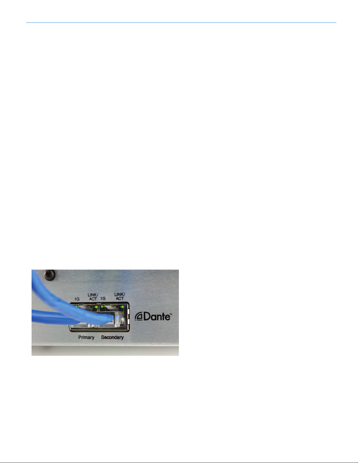
Switched and Redundant Modes
The rear panel Dante ports allow operation in a
switched mode through a single network using either
jack, or in a redundant mode through two separate
networks using both jacks simultaneously. Redundancy
is required in some applications where it is imperative
that no audio is lost due to network problems, such as
in courtroom recording. The secondary network duplicates real-time audio traffic. If the primary network fails
for any reason, the secondary network’s audio continues without losing even a single sample.
See page 15 and also refer to the help files and
documentation provided by Audinate for more information regarding the setup for switched and redundant
modes.
Audinate® is a registered trademark of Audinate Pty Ltd.
Rio Rancho, NM
5
Page 6
ASPEN Digital Processor
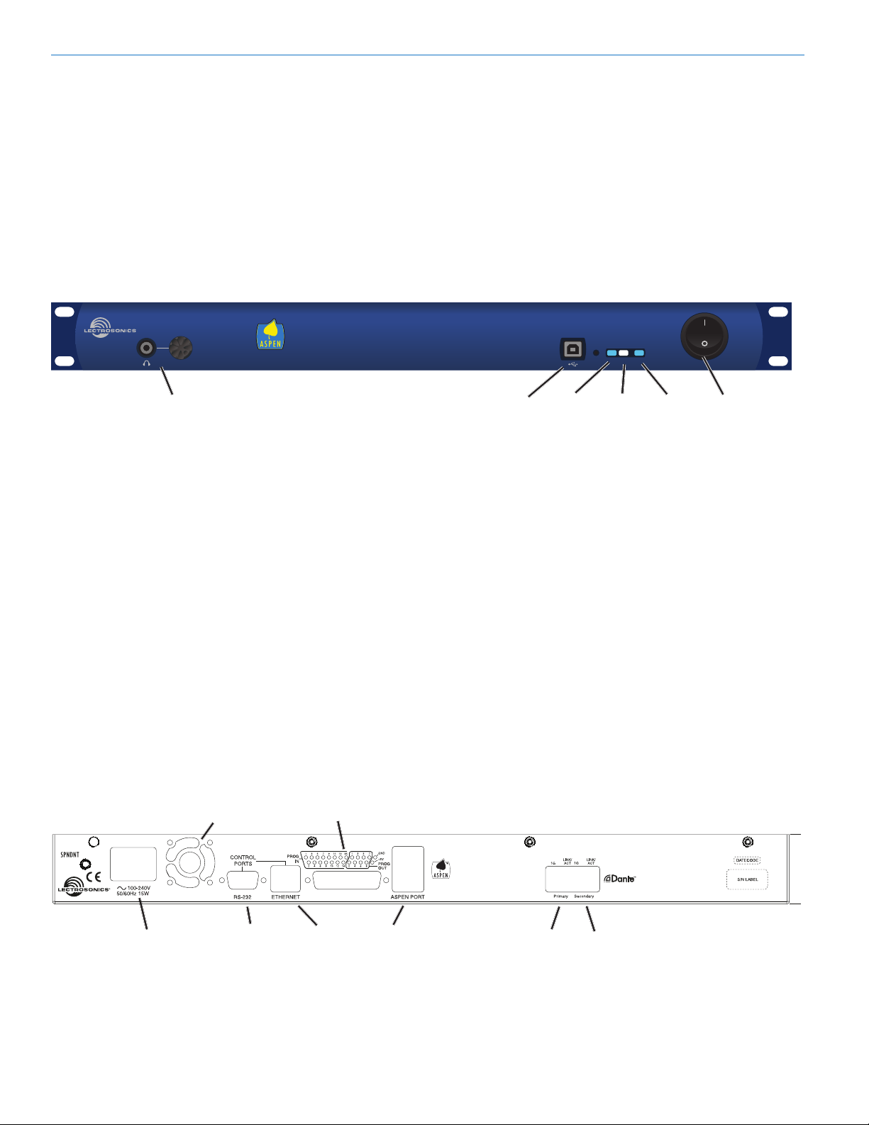
Front Panel
Headphone Monitor
Standard 1/4 inch jack and level control. Drives both
channels of stereo headphones.
USB Port
Standard USB connector for the setup and control
from a computer using Windows XP, Vista or Windows
7 operating system. The USB port is also used for
firmware updates.
DNT
Headphone Monitor
Rear Panel
Programmable Input and Output Ports
Programmable inputs and outputs used to control
levels, settings, indicate the current state of a programmable input and control a variety of other parameters.
Serial Port
Used for control; typically with third party products
such as touch panel displays.
Status LEDs
• CommLED-indicatesUSB,RS-232andnetwork
communication
• AlertLED-blinkstoindicatefaultorerror
• AlertLED-glowssteadyinrmwareupdatemode
• PowerLED-glowstoindicatepowerON
USB Port
Comm
LED
Alert
LED
Power
LED
POWER
Switch
Dante Ports
The network audio ports. Either port can be used with
a single network connection. When a second network
is configured for redundancy, all processors connected
to the network must have consistent connections, i.e.
all Primary ports connected to one network and all
Secondary ports connected to the other network.
Ethernet Port
Used for control only. Does not pass audio.
ASPEN Bus Data/Audio Ports
These RJ-45 jacks carry the audio signals and control
data between processors stacked together.
Cooling Fan
Outlet
Power Inlet
6
RS232
Serial Port
Programmable Input
and Output Ports
Ethernet
Port
Data/Audio
Bus Ports
Made In the USA
Primary Secondary
Dante Ports
LECTROSONICS, INC.
Page 7
USB Driver Installation
The ASPEN USB drivers are installed from the ASPEN
Installation Disk, which comes with each device, by
running the ASPEN Device Installer. Normally this is
done before connecting an ASPEN device to the PC
for the first time, but it can be done afterwards if necessary. The driver installation only needs to be done once
on each PC that will be connected to an ASPEN unit.
If an ASPEN device is connected to a PC without prior
installation of the drivers from the ASPEN Installation
Disk, manual installation is possible for Windows XP
and Vista operating systems using the New Hardware
Found wizard. In the case of Windows 7, there is no
New Hardware Found wizard, so manual installation is
a bit more involved. In any of these cases it’s not really
necessary if you have the installation disk. Just cancel
the New Hardware Found wizard (if open) and run the
ASPEN Device Installer from the Installation Disk.
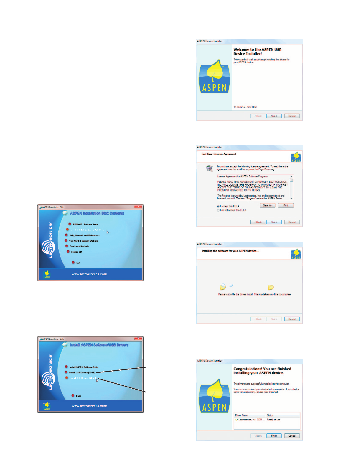
Installation with ASPEN Device Installer
Place the ASPEN Installation Disk into the CD-ROM
drive. If “AutoRun” is enabled on that drive then the
ASPEN Installation Disk utility will open. Click on
Install ASPEN Software/USB Drivers.
Installation and Quick Start Guide
The ASPEN Device Installer opens.
Click Next to proceed.
The End User License Agreement is presented.
Note: If AutoRun is not enabled use Start->Run
to run “autoRun.exe” on the drive holding the
ASPEN Install Disk. For example, if the CD-ROM
drive is drive E: then run “E:\autoRun.exe” to
open the ASPEN Software CD utility.
On the next screen, select the correct driver for your
operating system (32-bit or 64-bit).
32-bit Drivers
64-bit Drivers
Accept, then click Next to proceed.
The drivers are installed from the CD.
When installation is complete, the Driver Name and
Status are displayed. Click Finish to close the Device
Installer.
Rio Rancho, NM
7
Page 8
ASPEN Digital Processor
ASPEN Software
ASPEN Control Panel
ASPEN processors are set up and monitored using
the ASPEN Control Panel program. The software will
run on Windows 7, Windows Vista® and Windows XP®
operating systems.
Use the disk included with every processor to install
the software, or download the installer from the web
site at:
http://www.lectrosonics.com/aspensupport
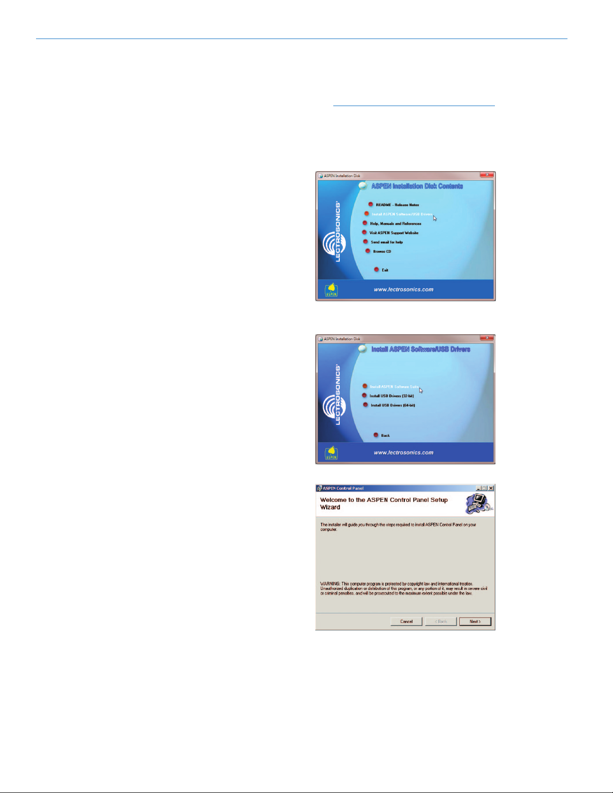
ASPEN Software
Installation
NOTE: Uninstall previous version before
installing the software.
Insert the disk into the drive and wait for the opening
screen to appear. Click on Install ASPEN Software to
launch the installer.
On the next screen, click on Install ASPEN Software
Suite.
When the Welcome screen appears, click on Next.
8
LECTROSONICS, INC.
Page 9
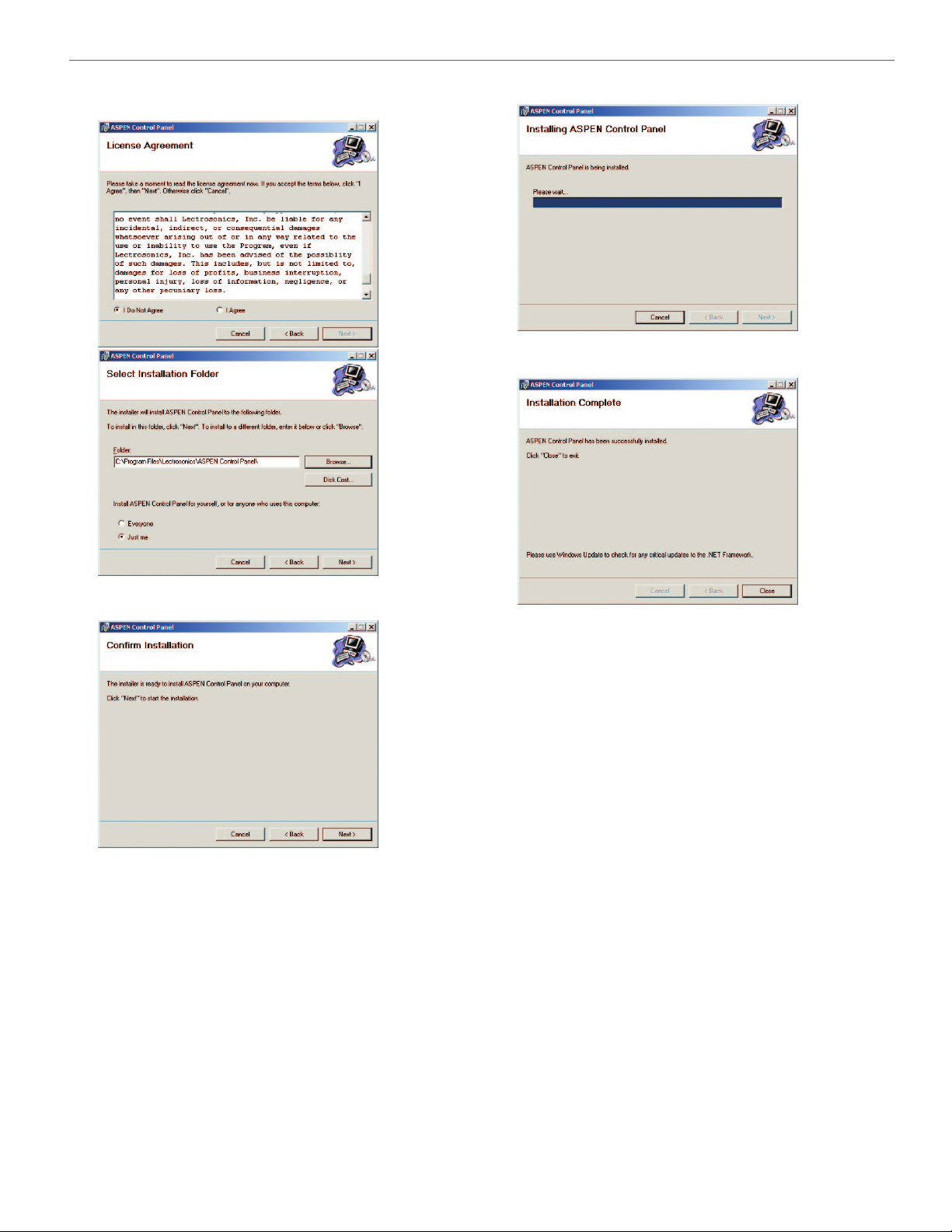
Installation and Quick Start Guide
The End User License Agreement screen appears.
Click on I Agree, then on Next to continue.
Click on Next to confirm the installation and continue.
When the installation is complete the final screen will
appear. Click on Close to finish the installation.
It is usually best to accept the default folder for the
installation. Click on Next to continue.
Rio Rancho, NM
9
Page 10

ASPEN Digital Processor
Dante Software
Dante Controller
This is a second software package needed to route
network audio signals between the SPNDNT and other
nodes on a Dante network. The software is downloaded from the Audinate web site and will run on Windows
and Mac platforms.
Dante Controller is
used to assign the
transmit and receive
signals between
multiple Dante
devices. When a
device is set to
receive a signal from
another device that
is transmitting, it is said to subscribe to the transmitted signal. These subscriptions appear in the Dante
Controller window as green check marks.
DanteTM Software
Installation
Bonjour Print Services (for Windows only)
Download the Bonjour Print Services for Windows
installer into a temporary folder or desktop on your PC.
http://support.apple.com/kb/DL999
Double click on the file to open the installer. If the
Security Warning dialog box opens, click on Run to
launch the installer and follow the on screen prompts.
Set Up Audinate Account and Download the
Dante Controller Installer
Set up an account with Audinate to gain access to the
free Dante Controller software. Click on Login at the
top of the screen and the forms page will open.
http://www.audinate.com
After your account is set up, return to the home page
and click on Support->Software Downloads->Dante
Controller. Log In on the next page and follow the on
screen prompts to download the installer and store the
file on your local drive.
Browser based Help Files are provided to explain various icons and setup tabs.
Download the software from: http://www.audinate.com
The installation is quick and simple.
10
Install Dante Controller
NOTE: Install Bonjour Print Services for
Windows before installing Dante Controller.
Double click on the downloaded file to open the installer. If the Security Warning dialog box opens, click
on Run to launch the installer and follow the on screen
prompts.
LECTROSONICS, INC.
Page 11

Mandatory Settings
Set up the system in the Switched Mode in the Network Config screen in Dante Controller. Once everything is set up and audio is flowing to and from the
network, a second network and gigabit switch can be
added and the mode can be changed to Redundant.
Connect an SPNDNT Dante port to the computer either
directly or through a gigabit switch.
Installation and Quick Start Guide
Dante Primary Port
Made In the USA
Connect the PC to the Primary Port in case the mode
had previously been set to Redundant. Confirm that
the 1G and LINK/ACT LEDs next to the Dante port are
flickering.
Launch the Dante Controller software. A brief splash
screen appears, followed by the Network View/Routing
screen. The serial number of the connected processor
will appear in the bars labeled Receivers and Trans-
mitters.
Processor name and
serial number appear in
the blue bars
Double click on either blue
bar to open the Device View
dialogue box
Select the Device Config tab, then set the sample
rate to 48k. The sample rate MUST be 48k so the DSP
(filters, etc.) will operate as they should.
Device Config Tab
Select 48k Sample Rate
Latency under the same tab can be adjusted depending upon the number of switches in the network.
The other tabs in the Device View dialog box are used
to rename channels and check the status of several
parameters.
Consult the Help menu for details and explanations of
Dante Controller software.
Double click on the processor name/serial number to
open the Device View dialog box. Under the Network
Config tab, select Switched.
Select
Network
Config
Select
Switched
Rio Rancho, NM
11
Page 12

ASPEN Digital Processor
88
8
11122
1612
Hardware Connections
Installing the chassis into a rack
Install the chassis so that the cooling fan vent is not
blocked. Mount with 4 rack screws using the appropriate mounting holes. Use nylon washers to prevent
damage to the front panel’s finish when tightening the
mounting screws.
All ASPEN processors have internal switching power
supplies that can tolerate voltages ranging from 100
to 240 VAC. Use an approved power cord with an IEC
60320 C13 connector.
Connecting the Master for the First Time
NOTE: Install ASPEN software before
connecting the Master unit to a computer.
The computer operating system will automatically detect and configure a USB port for the Master unit when
it is connected and turned on the first time. Wait for the
screen message that advises that the new device has
been configured and is ready for use.
Rear Panel
Review the rear panel connectors on page 6. Connectors are used for the following purposes.
Port Purpose
RS-232 Third party control devices such
as LCD touch panels
ETHERNET ASPEN control panel software
interface for setup, monitoring and
control
ASPEN
PORTS
DANTE Network audio I/O ports and setup
RS-232 is a common interface with LCD touch panel
control systems such as Crestron® and AMX®. The
wiring diagram for DB-9 connectors is shown on the
opposite page.
The ETHERNET port is used with ASPEN control
panel software for setup, monitoring, control and
diagnostics. It does not transport audio. IP addresses
can be set up statically, or one can be assigned by
a network server if DHCP is enabled in the software
control panel.
ASPEN Ports connect multiple processors for data and
signal flow. 2RU units have two internal circuit boards
that must be connected with cables in the same manner as two separate processors.
The DANTE ports connect to network switches.
Multiple SPNDNT processors can also be connected
directly to each other through these ports.
Interconnect multiple ASPEN
processors
with Dante Controller software
Cabling Of Stacked Units
NOTE: The SPNDNT must always be the Master
at the top of the stack to synchronize the ASPEN
system and network clocks.
The ASPEN bus is bidirectional, allowing data and
audio to be propagated forward and backward through
a single cable connection. Each Slave unit in a stack
gathers data and audio signals from the unit below it,
adds its own signals and passes the total on to the
unit above it. At the top of the stack, the Master unit
gathers all signals from below, adds its own and then
sends the total back down the bus to all Slave units.
This architecture allows all Slave units to have access
to the mixing data and audio in all 48 final mixes.
Each circuit board has an upper and a lower ASPEN
bus connector. Since there are two circuit boards in a
2RU unit such as the SPN1624, the circuit boards are
connected in the same manner as if they were each in
a separate chassis.
1RU SPNDNT
configured as
Master
ASPEN PORT
2RU SPN1624
configured as
intermediate
Slave
1RU SPN16i
configured
as lowermost
Slave
The processors automatically configure themselves for
Master and Slave status as determined by the cabling.
Front Panel USB Port
This is the easiest connection point to run ASPEN
control panel software until the network is configured
and IP addresses have been established. Connect the
computer to the Master unit in the ASPEN stack and
launch the control panel software. The Master unit will
appear on the screen, and the Slave units below it will
then be accessible as well.
DNT
1612
812
12
LECTROSONICS, INC.
Page 13

Installation and Quick Start Guide
1
2
3
4
5
6
7
8
9
1
2
3
4
5
6
7
8
9
DCD
RX
TX
DTR
GND
DSR
RTS
CTS
RI
TX
RX
GND
Host
Serial
Port
(PC)
ASPEN
RS-232
Port
Wiring Diagram
ASPEN Device to PC
DTE pin
functions
Female
connector
Male
connector
DCE pin
functions
Female
jack
Male jack
1
2
3
4
5
6
7
8
9
1
2
3
4
5
6
7
8
9
RX
TX
GND
TX
RX
GND
Crestron
RS-232
Port
ASPEN
RS-232
Port
Wiring Diagram
Female
connector
Male
connector
Female jack
Male jack
10K Linear Potentiometer
CCW
CW
+5V
To Programmable Input Pin
Gnd
Contact Closure as Programmable Input
To Programmable Input Pin
Gnd
DC Voltage Source as Programmable Input
To Programmable Input Pin
0VDC (Off) to +5VDC (On)
Gnd
Potentiometer Connection for
Analog Control of Gain
LOGIC INPUTS
ASPEN RS-232 Port
Crestron® RS-232 Port Wiring
Programmable Inputs
Programmable inputs are provided to enable external
control over a variety of parameters. Each input can
respond to a contact closure, a DC voltage source,
or the variable voltage output from a potentiometer.
The following illustrates common connections to the
programmable input pins.
Programmable Outputs
Programmable outputs are used for several purposes:
• indicatethecurrentstateofaprogrammableinput
• monitoractivityonaudioinputchannels
• monitoractivepresetchanges
Each programmable output is the electrical equivalent
of a contact closure to ground. When a programmable
output is “active” it conducts current to ground. When
the programmable output is “inactive,” no current flows
to ground. The maximum usable voltage for the programmable outputs is 40 V and they will safely conduct
up to 100 mA DC continuous.
Both LEDs and 5V relay coils can be powered by the
+5 V DC pins on the programmable input connector, as
long as the maximum combined current for all LEDS
and relay coils does not exceed 100 mA.
LED is ON when the programmable output is active
+5VDC
Pro gr amma b le Output Pi n
LED is OFF when the programmable output is active
+5VDC
Programmable Output Pin
Relay is on when the programmable output is active
Rel a y Coi l
Coil current <100mA
Pro gr amma b le Output Pi n
GND
Note: The diagram above shows an external DC source
powering the relay coil. This is necessary whenever coil voltages exceed 5 volts.
GND
380 Ohms
380 Ohms
1N4001
or equi v .
Exte r na l
DC V oltag e
Source
(<40VDC)
Programmable
Inputs
Rio Rancho, NM
Programmable
Outputs
Ground
+5VDC
LOGIC IN 3
IN 3
ON
OFF
CCW
IN 1
380 TO
500 OHM
ANODE CATHODE
CW
10K
LINEAR
POT
LOGIC OUTPUTS
GROUND
5VDC
LED
LOGIC
OUT 7
Anode
Cathode
13
Page 14

ASPEN Digital Processor
Network and PC
Connections
The SPNDNT processor must be the Master at the top
of the ASPEN stack to synchronize the system and
network clocks.
Gigabit ethernet switch
PROG IN
PROG IN
RS-232 ports for
external control system
SPN 1624
DATECODE
S/N LABEL
100-240V
50/60Hz 30W
PC
Adaptive Proportional Gain Mixing
US Patent 5,414,776
Supplied ASPEN cables
ETHERNET
RS-232
GND
+5V
PROG
OUT
ASPEN PORTS
GND
+5V
PROG
OUT
Server
CAT-6 cable
Audio I/O
OUTPUTS
OUTPUTS
Gigabit ethernet switch
Audio I/O
Network Audio Transport
Network Audio Transport
INPUTS
INPUTS
CAT-5 or better
cables
(optional)
Ethernet switch
These connections
are for setup and
control with ASPEN
Control Panel
software.
To front panel
USB port
OR
Using DHCP for IP Address Assignment
Follow these steps to make a network connection for
each processor:
1) Open the ASPEN Control Panel program and
connect to the processor via USB.
2) Click on the Device Settings tab (lower left)
then on the Network tab (left side). Click the
checkbox to enable DHCP.
3) Close the ASPEN Control Panel program.
4) Connect the network cable to the Ethernet port
on the rear panel.
5) Turn the processor power off then back on.
6) Open the ASPEN Control Panel program and
connect to the processor via USB.
7) Navigate to the Device Settings/Network tab
and make a note of the IP address and TCP
port number.
8) Close the USB connection and re-connect via
network. When the dialog box opens, enter the
IP address and the port number noted, then
click on Refresh. Click on the processor icon to
connect.
14
LECTROSONICS, INC.
Page 15

Secondary network for redundancy
CAT-6 cable
RS-232 ports for external control system
Installation and Quick Start Guide
SPN 1624
DATECODE
S/N LABEL
100-240V
50/60Hz 30W
Adaptive Proportional Gain Mixing
US Patent 5,414,776
CAT-5 or better
cables
(optional)
Ethernet switch
These connections
are for setup and
control with ASPEN
Control Panel
software.
RS-232
PROG IN
PROG IN
ETHERNET
OR
GND
+5V
PROG
OUT
ASPEN PORTS
GND
+5V
PROG
OUT
To front panel
USB port
OUTPUTS
OUTPUTS
INPUTS
INPUTS
Supplied ASPEN cables
Using Switched and Redundant Modes
NOTE: See page 11 for instructions on
selecting the mode using Dante Controller
software.
Set processors to the Switched mode for setup.
In the Switched mode, the Primary and Sec-
ondary ports can be connected in any combination since there is an ethernet switch in the
hardware.
In the Redundant mode, the Primary ports on
all processors must be connected to the first network and the Secondary ports on all processors
must be connected to the second network.
After all connections and settings are completed
and the system is passing audio through the network, connect the second network and set the
processors to the Redundant mode.
Rio Rancho, NM
15
Page 16

ASPEN Digital Processor
System Setup Examples
Basic Configuration
X = INPUT
O = OUTPUT
This example illustrates the basic signal routing between two ASPEN subsystems connected via a Dante
network. This setup creates a “full-duplex” connection
where each ASPEN subsystem transmits and receives
signals simultaneously as might be used to conduct
conferencing between two meeting rooms. In this example, no local sound reinforcement is in use.
The success of this setup could be limited by loudspeaker/microphone acoustical coupling in the sound
systems in each room. If the level of the sound from
the loudspeakers arriving at each microphone is not far
below the loudness of the talker, an echo will be heard
at the far end (opposite ASPEN system). With careful
placement of loudspeakers and microphones, and the
use of mix-minus zoning, this type of system can be
used.
NOTE: See the next example regarding the use
of the AEC (acoustic echo canceller) on network
connections.
In the ASPEN subsystem on the left, the blue lines
indicate inputs with the signal path starting at the
microphones. The audio is routed to Mix 1 and Mix 2 in
the ASPEN matrix, which are then assigned to Dante
transmit channels 1 and 2 (labeled Out 1 and Out 2) in
the SPNDNT processor.
In the ASPEN subsystem on the right, Dante receive
channels 1 and 2 are assigned to Mix 1 and Mix 2 in
the ASPEN matrix by the SPNDNT processor. These
two mixes are then selected as the signal sources for
outputs 1 and 2 of the mixer.
The reverse of this signal flow (in red) from the ASPEN
system on the right to the system on the left takes
place through ASPEN Mixes 3 and 4, and Dante transmit channels 3 and 4.
Each ASPEN system is an independent sub-system,
so the Mix numbers used in one system have no bearing on those used in any other ASPEN sub-system.
The Mix numbers used here were chosen only for clarity in visualizing the signal paths.
16
LECTROSONICS, INC.
Page 17

Installation and Quick Start Guide
Set up the inputs for the microphones with the gain
value set to achieve 0 dBu on the meter during speech.
Select mixer
Inputs tab
Audio level meter
Select the source signal to be delivered to the outputs.
• ForsubsystemA:Mix3toOut3;Mix4toOut4
• ForsubsystemB:Mix1toOut1;Mix2toOut2
Select mixer Output Source tab
Route the microphone inputs to Mix 1 and Mix 2 on
subsystem A and Mix 3 and Mix 4 on subsystem B
under the matrix tab (subsystem A shown).
Select mixer Matrix tab
Assign Dante receive channels 3 and 4 to Mixes 3 and
4 respectively in the SPNDNT processor in subsystem A and Dante channels 1 and 2 to Mixes 1 and 2
respectively in subsystem B (subsystem A shown)
Select SPNDNT
Matrix tab
Select the signal sources to deliver audio to the network from The SPNDNT in each subsystem.
• ForsubsystemA:Mix1forOut1
• ForsubsystemB:MIx2forOut2
Select SPNDNT Output Source tab
Rio Rancho, NM
Create Dante subscriptions in a diagonal pattern: 1:1,
2:2, 3:3, 4:4.
17
Page 18

ASPEN Digital Processor
Using the AEC on Network Connections
When the Trio or Conference processor is used in the
ASPEN subsystem, the AEC (acoustic echo canceller)
can be applied to the network connections to suppress
echo caused by acoustical coupling between microphones and loudspeakers. In this example, a local
sound reinforcement system is in place, which further
increases the potential echo.
SUBSYSTEM A
(1->1, 2->2...)
(1->1, 2->2...)
(1->1, 2->2...)
(1->1, 2->2...)
SUBSYSTEM B
18
INPUTS
OUTPUTS
LECTROSONICS, INC.
Page 19

Installation and Quick Start Guide
Assign the two microphone inputs to Mix Buses 16 and
17 to be used for local sound reinforcement. Make the
assignments under the SPNTrio matrix tab.
Select SPNTrio Matrix tab
Assign the AEC output to Mix 1, which is the signal
source for the audio sent to the other ASPEN system
via the network.
Select SPNTrio
Matrix tab
Assign the two microphone inputs to Mix Bus 47 to deliver audio to the other ASPEN system via the network.
Make the assignments under the SPNTrio matrix tab.
Select SPNTrio
Matrix tab
Assign the Signal Mix and Reference Mix in the
SPNTrio under the Conferencing tab. The Signal Mix
contains the audio from the local microphones. The
Reference Mix contains the audio from the other
ASPEN system which the AEC cancels to remove an
echo that might be heard due to coupling between the
local microphones and loudspeakers.
Select SPNTrio Conferencing tab
Select Mixes 16 and 17 as the signal source for the
power amp outputs to feed the local loudspeakers.
Select SPNTrio Output Source tab
Rio Rancho, NM
(See next page)
19
Page 20

ASPEN Digital Processor
Assign the Dante receive channel 1 to Mixes 16 and
17 to deliver the audio from the network into the local
sound system under the SPNDNT Matrix tab.
Select SPNDNT
Matrix tab
Subscribe to the transmit channels from the opposite
ASPEN subsystems to flow audio back and forth between the ASPEN systems.
Assign Dante receive channel 1 to Mix 48 to deliver
the audio from the network to the AEC to provide a
reference signal for echo cancellation.
Select SPNDNT Matrix tab
Audio from sub system B to sub system A via
subscription on subsystem A receive channel 1
to flow from subsystem B transmit channel 1.
Audio from system A to system B via
subscription on subsystem B receive channel 1
to flow from subsystem A transmit channel 1.
20
LECTROSONICS, INC.
Page 21

Installation and Quick Start Guide
Rio Rancho, NM
21
Page 22

ASPEN Digital Processor
Multiple Site Conferencing
This example illustrates how multiple ASPEN subsystems can be set up identically and use Dante channels
to transmit and receive audio.
22
LECTROSONICS, INC.
Page 23

Installation and Quick Start Guide
Route the inputs as follows:
• In1toMix1andMix5
• In2toMix2andMix5
In this example, Mixes 1 and 2 are routed to the local
sound system in a mix-minus pattern. Mix 5 delivers
the audio from the local microphones into the Dante
network.
Select SPNTrio Matrix tab
Route the Dante network channels in the SPNDNT as
follows:
• In1toMix3
• In2toMix4
This will provide the audio source from the network to
the local sound system.
Select SPNDNT
Matrix tab
Set up the inputs for the microphones connected to the
SPNTrio. Adjust the gain so the level is close to 0dBu
during normal speech.
Select SPNTrio Inputs tab
Select the signal sources for the output channels on
the SPNTrio to feed the local sound system.
Select SPNTrio
Output Source tab
Rio Rancho, NM
Output Channel Signal Source
1 Mix 2
2 Mix 1
3 Mix 3
4 Mix 4
Outputs 1 and 2 are configured in a “criss cross” manner to imply that there is a mix-minus arrangement in
the local sound system.
Outputs 3 and 4 deliver the audio from the other two
ASPEN systems on the network into the local sound
system.
(see next page)
23
Page 24

ASPEN Digital Processor
In this example, the processors in the subsystems all
subscribe to receive audio from the other two subsystems on Dante transmit channels 1 and 2.
A system configuration like this would be an ideal solution for multi-site Telepresence video conferencing by
allowing a full-duplex, system wide audio signal flow.
SPNDNT 102
Transmit
Channels
These areas grayed out
because a Dante device
cannot transmit to itself
SPNDNT 102
Receive Channels
This setup is also an effective solution for signal routing in room combining systems.
SPNDNT 106
Transmit
Channels
SPNDNT 102 subscriptions
to other two transmitters
SPNDNT 115
Transmit
Channels
SPNDNT 106
Receive Channels
SPNDNT 115
Receive Channels
SPNDNT 106 subscriptions
to other two transmitters
SPNDNT 115 subscriptions
to other two transmitters
24
LECTROSONICS, INC.
Page 25

Installation and Quick Start Guide
Rio Rancho, NM
25
Page 26

ASPEN Digital Processor
FCC Part 15 Compliance
This device complies with Part 15 of the FCC Rules.
Operation is subject to the following two conditions: (1)
This device may not cause harmful interference, and
(2) this device must accept any interference received,
including interference that may cause undesired operation.
CAUTION: Changes or modifications not expressly
approved by Lectrosonics, Inc. could void the user’s
authority to operate the equipment.
This equipment has been tested and found to comply
with the limits for a Class A digital device, pursuant to
Part 15 of the FCC Rules. These limits are designed to
provide reasonable protection against harmful interference when the equipment is operated in a commercial
environment. This equipment generates, uses, and can
radiate radio frequency energy and, if not installed and
used in accordance with the instruction manual, may
cause harmful interference to radio communications.
Operation of this equipment in a residential area is
likely to cause harmful interference in which case the
user will be required to correct the interference at this
own expense.
26
LECTROSONICS, INC.
Page 27

Installation and Quick Start Guide
Service and Repair
If your system malfunctions, you should attempt to correct or isolate the trouble before concluding that the equipment needs repair. Make sure you have followed the setup procedure and operating instructions. Check the interconnecting cables and then go through the Troubleshooting section in this manual.
We strongly recommend that you do not try to repair the equipment yourself and do not have the local repair shop
attempt anything other than the simplest repair. If the repair is more complicated than a broken wire or loose connection, send the unit to the factory for repair and service. Don’t attempt to adjust any controls inside the units.
Once set at the factory, the various controls and trimmers do not drift with age or vibration and never require readjustment. There are no adjustments inside that will make a malfunctioning unit start working.
LECTROSONICS’ Service Department is equipped and staffed to quickly repair your equipment. In warranty repairs
are made at no charge in accordance with the terms of the warranty. Out-of-warranty repairs are charged at a modest flat rate plus parts and shipping. Since it takes almost as much time and effort to determine what is wrong as it
does to make the repair, there is a charge for an exact quotation. We will be happy to quote approximate charges by
phone for out-of-warranty repairs.
Returning Units for Repair
For timely service, please follow the steps below:
A. DO NOT return equipment to the factory for repair without first contacting us by e-mail or by phone. We need
to know the nature of the problem, the model number and the serial number of the equipment. We also need a
phone number where you can be reached 8 A.M. to 4 P.M. (U.S. Mountain Standard Time).
B. After receiving your request, we will issue you a return authorization number (R.A.). This number will help
speed your repair through our receiving and repair departments. The return authorization number must be
clearly shown on the outside of the shipping container.
C. Pack the equipment carefully and ship to us, shipping costs prepaid. If necessary, we can provide you with
the proper packing materials. UPS or FEDEX is usually the best way to ship the units. Heavy units should be
“double-boxed” for safe transport.
D. We also strongly recommend that you insure the equipment, since we cannot be responsible for loss of or dam-
age to equipment that you ship. Of course, we insure the equipment when we ship it back to you.
Lectrosonics USA:
Mailing address: Shipping address: Telephone:
Lectrosonics, Inc. Lectrosonics, Inc. (505) 892-4501
PO Box 15900 581 Laser Rd. (800) 821-1121 Toll-free
Rio Rancho, NM 87174 Rio Rancho, NM 87124 (505) 892-6243 Fax
USA USA
Web: E-mail:
www.lectrosonics.com sales@lectrosonics.com
Lectrosonics Canada:
Mailing Address: Telephone: E-mail:
49 Spadina Avenue, (416) 596-2202 Sales: colinb@lectrosonics.com
Suite 303A (877) 753-2876 Toll-free Service: joeb@lectrosonics.com
Toronto, Ontario M5V 2J1 (877-7LECTRO)
(416) 596-6648 Fax
Rio Rancho, NM
27
Page 28

581 Laser Road NE • Rio Rancho, NM 87124 USA • www.lectrosonics.com
(505) 892-4501 • (800) 821-1121 • fax (505) 892-6243 • sales@lectrosonics.com
LIMITED THREE YEAR WARRANTY
The equipment is warranted for three years from date of purchase against defects in
materials or workmanship provided it was purchased from an authorized dealer. This
warranty does not cover equipment which has been abused or damaged by careless
handling or shipping. This warranty does not apply to used or demonstrator equipment.
Should any defect develop, Lectrosonics, Inc. will, at our option, repair or replace any
defective parts without charge for either parts or labor. If Lectrosonics, Inc. cannot
correct the defect in your equipment, it will be replaced at no charge with a similar new
item. Lectrosonics, Inc. will pay for the cost of returning your equipment to you.
This warranty applies only to items returned to Lectrosonics, Inc. or an authorized
dealer, shipping costs prepaid, within three years from the date of purchase.
This Limited Warranty is governed by the laws of the State of New Mexico. It states the
entire liablility of Lectrosonics Inc. and the entire remedy of the purchaser for any
breach of warranty as outlined above. NEITHER LECTROSONICS, INC. NOR
ANYONE INVOLVED IN THE PRODUCTION OR DELIVERY OF THE EQUIPMENT
SHALL BE LIABLE FOR ANY INDIRECT, SPECIAL, PUNITIVE, CONSEQUENTIAL,
OR INCIDENTAL DAMAGES ARISING OUT OF THE USE OR INABILITY TO USE
THIS EQUIPMENT EVEN IF LECTROSONICS, INC. HAS BEEN ADVISED OF THE
POSSIBILITY OF SUCH DAMAGES. IN NO EVENT SHALL THE LIABILITY OF
LECTROSONICS, INC. EXCEED THE PURCHASE PRICE OF ANY DEFECTIVE
EQUIPMENT.
This warranty gives you specific legal rights. You may have additional legal rights which
vary from state to state.
13 March 2013
 Loading...