

Page 1
SMKITTA5
Wiring for UHF Transmitters
The diagrams shown on page 3 represent the
basic wiring necessary for the most common
types of microphones and other audio inputs.
Some microphones may require extra jumpers
or a slight variation on the diagrams shown.
TECHNICAL DATA
If you encounter a microphone that differs from or
is not included in these instructions, please call
our toll-free number or visit our web site at:
www.lectrosonics.com
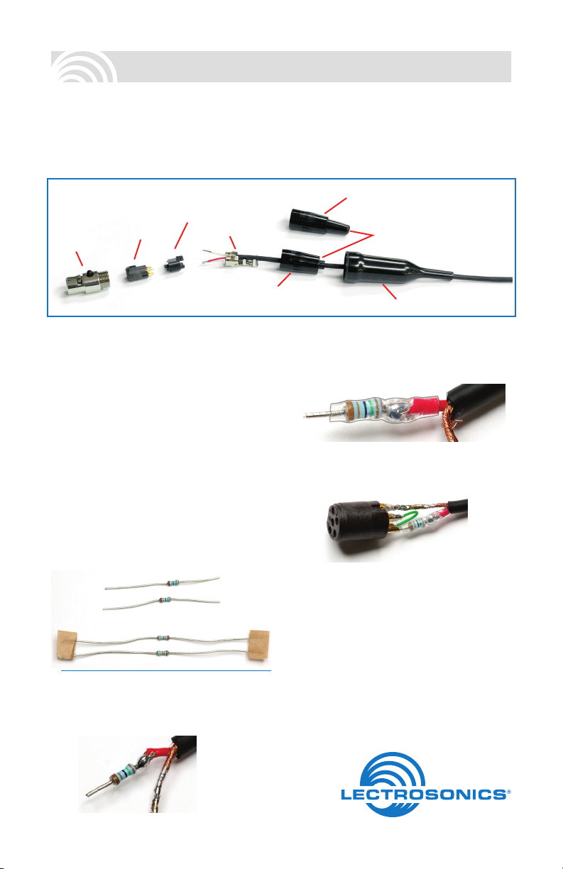
Component Parts
Insulator
Latchlock
Insert
Installing the Connector:
1) If necessary, remove the old connector from
microphone cable.
2) Slide the Dust Boot onto microphone cable
as shown. Remove the Strain Relief from
the backshell (if present).
3) If necessary, slide the supplied 1/8-inch
diameter black shrink tubing onto the microphone cable to ensure that the cable fits
snugly in the Dust Boot.
4) If required, use the resistors included with
this kit to configure the TA5F to your particular microphone according to the wiring
diagrams on page 3.
Resistors included:
•Two1.5Kohm(shorterleads)
•Two3.32Kohm(longerleads)
NOTE: The resistors may also be supplied on a
card with the values indicated.
The resistors are soldered onto the wires as
indicated in the diagrams on page 3.
Cable Clamp
TA5F Backshell
(Strain Relief removed)
TA5F Backshell
with Strain Relief
Remove strain relief
if using dust boot
Dust Boot
Slide a length of the supplied .065” OD clear
tubing over the resistor and wire before
soldering the resistor to the pin.
5) Run the wires through the Insulator and
solder the resistors to the correct pins on the
Insert as indicated in the diagrams.
6) Align the flat sides and attach the Insulator
to the Insert.
7) Slide the Cable Clamp over the wires and
attach it to the insert. Crimp the fingers as
shown on the following page, leaving a little
slack in the wires between the fingers and
the insert.
8) Slide the completed assembly into the
Latchlock. Orient the tab on the Insert to
align with the notch in the Latchlock to
allow it to fully seat. Thread the Backshell
onto the Latchlock and tighten it.
Page 2
Microphone Cable Termination
for Non-Lectrosonics Microphones
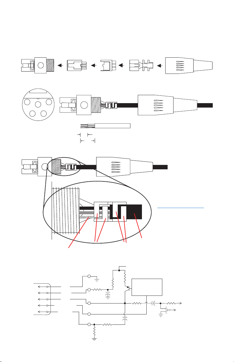
TA5F Connector Assembly
Cable Stripping Instructions
1
4
5
23
VIEW FROM SOLDER
SIDE OF PINS
0.15"
0.3"
Crimping to Shield and Insulation
Shield
Crimp these
fingers to contact
the shield
Insulation
Crimp these
fingers to clamp
the insulation
+5 VDC
Strip and position the cable so that
the clamp fingers can be crimped
to contact both the mic cable shield
and the insulation. The shield
contact reduces noise with some
microphones and the insulation
clamp increases ruggedness.
NOTE: This termination is
intended for UHF transmitters
only. VHF transmitters with
5-pin jacks require a different
termination. Visit the website
for details. Search: “mic wiring.”
Servo Bias
500 Ohm
10k
1k
+
30uF
1
2
3
4
5
GND
BIAS
MIC
BIAS SELECT
LINE IN
100 Ohm
2.7K
Pin 4 to Pin 1 = 0 V
Pin 4 Open = 2 V
Pin 4 to Pin 2 = 4 V
30uF
100 Ohm
+
To Virtual Ground
Audio Amplifier
To Limiter Control
+
200 Ohm
3.3uF
SM Equivalent Input Circuit Wiring
Page 3
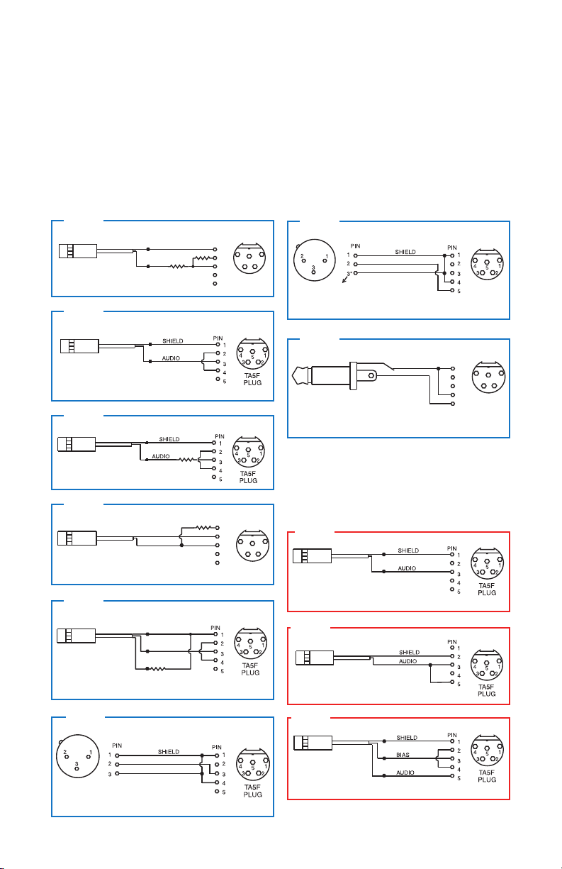
Wiring Hookups for Different Sources
SHIELD
TIP
PIN
5
4
3
2
1
SLEEVE
LINE LEVEL
RCA or 1/4” PLUG
AUDIO
1
2
3
4
5
TA5F
PLUG
UNBALANCED LINE LEVEL SIGNALS
Up to 3V (+12 dBu) levels before limiting.
Fully compatible with 5-pin inputs on non-ServoBias transmitters. 20k ohm
resistor can be inserted in series with Pin 5 for 20 dB of attenuation to handle
up to 30V (+32 dBu).
BALANCED AND FLOATING LINE LEVEL SIGNALS
4 VOLT POSITIVE BIAS 3-WIRE ELECTRET
PLUG
2 VOLT POSITIVE BIAS 2-WIRE ELECTRET
LO-Z MICROPHONE LEVEL SIGNALS
In addition to the microphone and line level
wiring hookups illustrated below, Lectrosonics
makes a number of cables and adapters for
other situations such as connecting musical
instruments (guitars, bass guitars, etc.) to the
transmitter. Visit www.lectrosonics.com and
click on Accessories, or download the master
catalog.
Compatible Wiring for Both Servo Bias Inputs and Earlier Transmitters:
Fig. 1
3.32k
3.32k
1.5k
3.32k
PIN
1
2
4
5
3
3
4
T A5 F
5
PIN
1
2
4
3
3
4
5
T A5 F
PLUG
SHIELD
Compatible wiring for microphones
such as Countryman E6/B6
A UDI O
.
Fig. 2
4 VOLT POSITIVE BIAS 2-WIRE ELECTRET
Most common type of wiring for lavaliere mics.
Fully compatible with 5-pin inputs on Lectrosonics
transmitters such as the LM and UM Series. This is
the standard wiring for the Lectrosonics M152.
Fig. 3
DPA MICROPHONES (Danish Pro Audio miniature models)
This wiring is for DPA lavalier
and headset microphones.
NOTE: The resistor value can range from 3k to 4k ohms.
Fig. 4
2 VOLT NEGATIVE BIAS 2-WIRE ELECTRET
SHIELD
Compatible wiring for microphones such as
negative bias TRAM models.
NOTE: The resistor value can range from 2k to 4k ohms.
AUDIO
Fig. 5
4 VOLT POSITIVE BIAS 3-WIRE ELECTRET
WITH EXTERNAL RESISTOR
Used for 3-wire lavaliere
microphones that require an
external resistor such as the
Sanken COS-11.
This wiring is fully compatible with 5-pin inputs on ServoBias
and non-ServoBias Lectrosonics transmitters.
SHIELD
DRAIN (BIAS)
SOURCE (AUDIO)
1.5k
Fig. 6
A lot of information regarding microphone wiring
is also available in the FAQ section of the web
site at:
http://www.lectrosonics.com/faq.htm
Follow the instructions to search by model number or other search options.
Fig. 7
1
2
XLR JACK
*NOTE: If the output is balanced but center tapped to ground, as on all
Lectrosonics receivers, do not connect Pin 3 of the XLR jack to Pin 4 of the TA5F
connector.
Fig. 8
Simple Wiring - Can ONLY be used
with Servo Bias Inputs:
Fig. 9
2 VOLT POSITIVE BIAS 2-WIRE ELECTRET
1
5
2
Simplified wiring for
microphones such as
Countryman B6/E6.
NOTE: This servo bias wiring is not compatible with earlier
(non-ServoBias) versions of Lectrosonics transmitters.
Fig. 10
2 VOLT NEGATIVE BIAS 2-WIRE ELECTRET
Simplified wiring for microphones
such as negative bias TRAM.
NOTE: This servo bias wiring is not compatible with earlier
(non-ServoBias) versions of Lectrosonics transmitters.
Fig. 11
TA5F
PLUG
XLR JACK
For low impedance dynamic mics or electret
mics with internal battery or power supply.
Insert 1k resistor in series with pin 3 if attenuation is needed.
NOTE: This servo bias wiring is not compatible with earlier
(non-ServoBias) versions of Lectrosonics transmitters.
Page 4
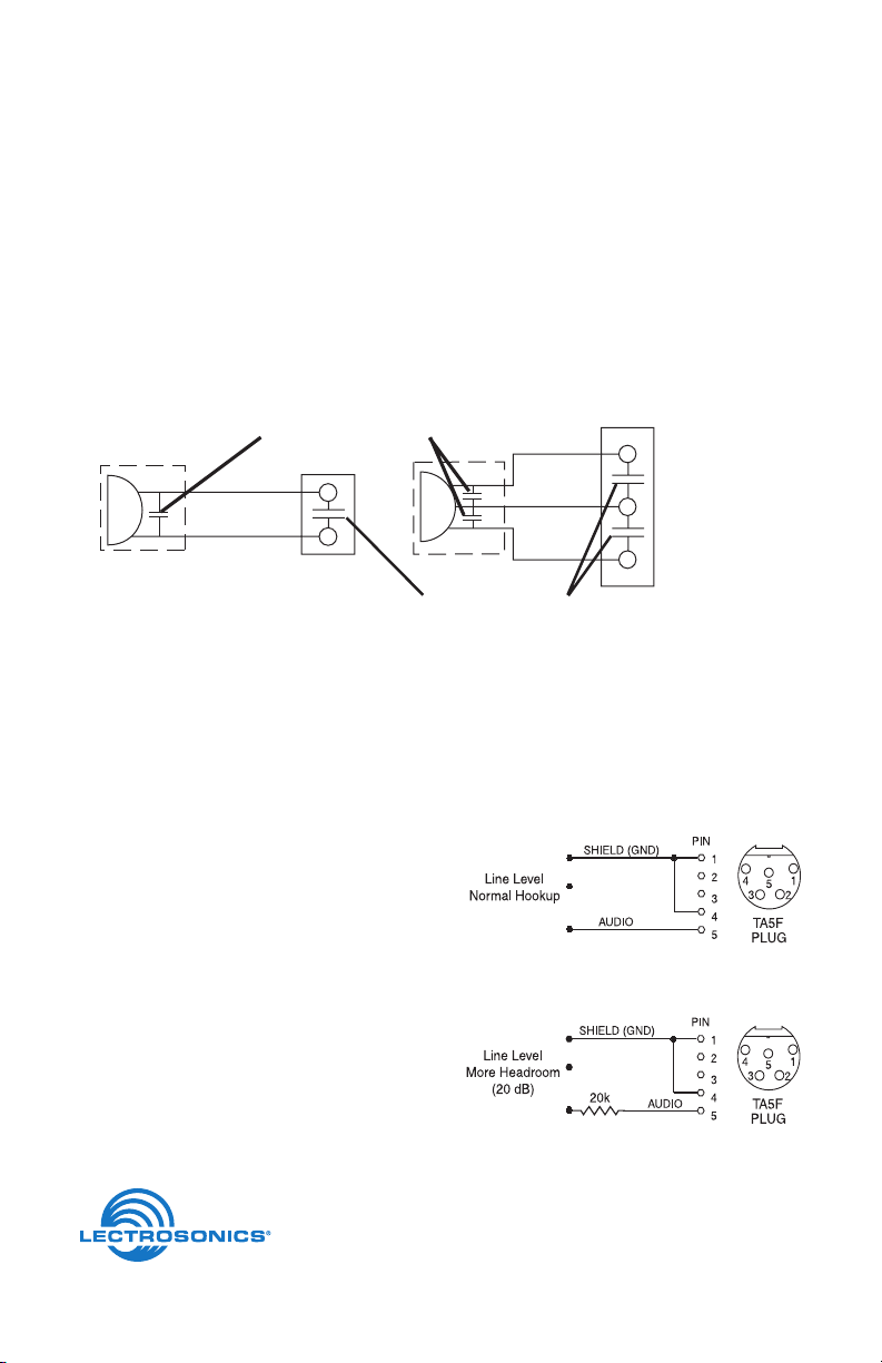
Microphone RF Bypassing
3 WIRE MIC2 WIRE MIC
When used on a wireless transmitter, the microphone element is in the proximity of the RF coming
from the transmitter. The nature of electret microphones makes them sensitive to RF, which can cause
problems with the microphone/transmitter compatibility. If the electret microphone is not designed
properly for use with wireless transmitters, it may be necessary to install a chip capacitor in the mic
capsule or connector to block the RF from entering the electret capsule.
Some mics require RF protection to keep the radio signal from affecting the capsule, even though the
transmitter input circuitry is already RF bypassed (see schematic diagram).
If the mic is wired as directed, and you are having difficulty with squealing, high noise, or poor frequency response, RF is likely to be the cause.
The best RF protection is accomplished by installing RF bypass capacitors at the mic capsule. If this
is not possible, or if you are still having problems, capacitors can be installed on the mic pins inside
the TA5F connector housing.
CAPSULE
Preferred locations for bypass capacitors
SHIELD
AUDIO
TA5F
CONNECTOR
Alternate locations for bypass capacitors
CAPSULE
SHIELD
AUDIO
BIAS
TA 5F
CONNECTOR
Install the capacitors as follows: Use 330 pF capacitors. Capacitors are available from Lectrosonics.
Please specify the part number for the desired lead style.
Leaded capacitors: P/N 15117
Leadless capacitors: P/N SCC330P
All Lectrosonics lavaliere mics are already bypassed and do not need any additional capacitors
installed for proper operation.
Line Level Signals
The normal hookup for line level signals is:
• SignalHottopin5
• SignalGndtopin1
• Pin4jumpedtopin1
This allows signal levels up to 3V RMS to be applied without limiting.
If more headroom is needed, insert a 20 k resistor in series with pin 5. Put this resistor inside the
TA5F connector to minimize noise pickup.
581 Laser Road NE • Rio Rancho, NM 87124 USA • www.lectrosonics.com
(505) 892-4501 • (800) 821-1121 • fax (505) 892-6243 • sales@lectrosonics.com
1 June 2011
 Loading...