

Page 1

Quick
Start
Guide
Wireless Microphone Transmitters
and Recorders
SMWB, SMDWB, SMWB/E01, SMDWB/E01, SMWB/X, SMDWB/X
Fill in for your records:
Serial Number:
Purchase Date:
Digital Hybrid Wireless® US Patent 7,225,135
This guide is intended to assist with
initial setup and operation of your
Lectrosonics product.
For a detailed user manual, download the most current
version at:
www.lectrosonics.com
13 March 2020
Page 2

SMWB Series
The SMWB transmitter delivers the advanced technology and features of Digital
Hybrid Wireless
radio link to eliminate a compandor and its artifacts, yet preserves the extended
operating range and noise rejection of the finest analog wireless systems. DSP
“compatibility modes” allow the transmitter to also be used with a variety of
analog receivers by emulating the compandors found in earlier Lectrosonics
analog wireless and IFB receivers, and certain receivers from other manufacturers (contact the factory for details).
Plus, the SMWB has a built in recording function for use in situations where RF
may not be possible or to work as a stand alone recorder. The record function
and transmit functions are exclusive of each other - you cannot record AND
transmit at the same time. The recorder samples at 44.1kHz rate with a 24 bit
sample depth. (the rate was selected due to the required 44.1kHz rate used for
the digital hybrid algorithm). The micro SDHC card also offers easy firmware
updates capability without the need for a USB cable.
®
and combines 24-bit digital audio chain with an analog FM
Controls and Functions
Modulation
Indicators
Indicates micro
SDHC card present
and recording
status (stopped/not
recording)
microSDHC memory
Antenna
Port
card port
Audio
Input
Jack
REC
-40
-20
0
Antenna
Port
Battery
Status LED
microSDHC
memory card
port
Audio
Input
Jack
LECTROSONICS, INC.2
Page 3
Battery Installation
The transmitters are powered by AA battery(ies). We recommend using
lithium for longest life.
Because some batteries run down quite abruptly, using the Power LED to
verify battery status will not be reliable. However, it is possible to track battery
status using the battery timer function available in Lectrosonics Digital Hybrid
Wireless receivers.
The battery door opens by simply unscrewing the knurled knob part way
until the door will rotate. The door is also easily removed by unscrewing the
knob completely, which is helpful when cleaning the battery contacts. The
battery contacts can be cleaned with alcohol and a cotton swab, or a clean
pencil eraser. Be sure not to leave any remnants of the cotton swab or eraser
crumbs inside the compartment.
A small pinpoint dab of silver conductive grease* on the thumbscrew threads
can improve battery performance and operation. Do this if you experience a
drop in battery life or an increase in operating temperature.
Insert the batteries according to the markings on the back of the housing. If
the batteries are inserted incorrectly, the door may close but the unit will not
operate.
*if you are unable to locate a supplier of this type of grease - a local electronics shop for example - contact the factory for a small maintenance vial.
Turning Power ON
Short Button Press
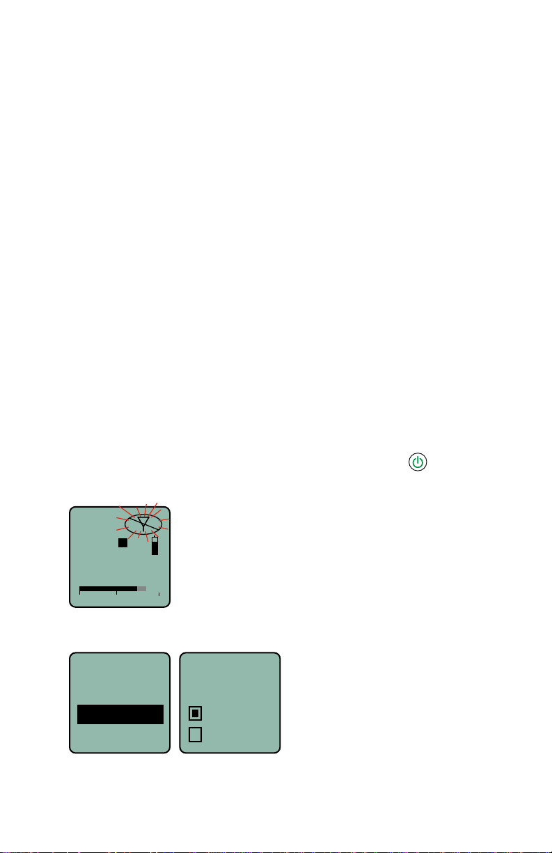
When the unit is turned off, a short press of the power button will turn the
unit on in the Standby Mode with the RF output turned off.
RF indicator blinks
b 19
A
E
494.500
-40
-20
0
To enable the RF output from the Standby Mode, press the Power Button,
select Rf On? option, then select yes.
Resume
Rf On?
Pwr Off
Rf On?
AutoOn?
www.lectrosonics.com 3
No
Ye s
Page 4

Long Button Press
When the unit is turned off, a long press of the power button will start a countdown to turn the unit on with the RF output turned on. Continue to hold the
button until the countdown is complete.
RF indicator not blinking
Hold
for
Rf On
Hold power
button until
the counter
reaches 3
b 19
A
E
503.800
...3
-40
-20
0
If the button is released before the countdown is completed, the unit will
power up with the RF output turned off.
Power Button Menu
When the unit is already turned on, the Power Button is used to turn the unit
off, or to access a setup menu.
A long press of the button begins a countdown to turn the unit off.
A short press of the button opens a menu for the following setup options. Select the option with the UP and DOWN arrow buttons then press MENU/SEL.
• Resume returns the unit to the previous screen and operating mode
• Pwr Off turns the unit off
• Rf On? turns the RF output on or off
• AutoOn? selects whether or not the unit will turn on automatically after a
battery change
• Remote enables or disables the audio remote control (dweedle tones)
• Bat Type selects the type of battery in use
• Backlit sets the duration of the LCD backlight
• Clock sets the Year/Month/Day/Time
• Locked disables the control panel buttons
• LED Off enables/disables control panel LEDs
• About displays the model number and firmware revision
Menu Shortcuts
From the Main/Home Screen, the following shortcuts are available:
• Record: Press the MENU/SEL + UP arrow simultaneously
• Stop Recording: Press the MENU/SEL + DOWN arrow simultaneously
NOTE: The shortcuts are only available from the main/home screen
AND when a microSDHC memory card is installed.
LECTROSONICS, INC.4
Page 5
Transmitter Operating Instructions
• Install battery(s)
• Turn power on in the Standby mode (see previous section)
• Connect microphone and place it in the position where it will be used.
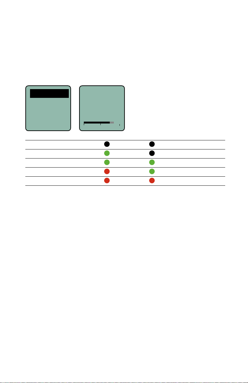
• Have the user talk or sing at the same level that will be used in the
production, and adjust the input gain so that the -20 LED blinks red on
louder peaks.
Gain
Gain
Freq
Rolloff
Compat
Signal Level -20 LED -10 LED
Less than -20 dB
-20 dB to -10 dB
-10 dB to +0 dB
+0 dB to +10 dB
Greater than +10 dB
• Set the frequency and compatibility mode to match the receiver.
• Turn the RF output on with the Rf On? item in the power menu, or by
turning the power off and then back on while holding the power button in
and waiting for the counter to reach 3.
-40
-20
Off Off
Green Off
Green Green
Red Green
Red Red
Use the UP and DOWN
arrow buttons to adjust
25
the gain until the -20
LED blinks red on
louder peaks
0
www.lectrosonics.com 5
Page 6
Record Operating Instructions
• Install battery(s)
• Insert microSDHC memory card
• Turn power on
• Format memory card
• Connect microphone and place it in the position where it will be used.
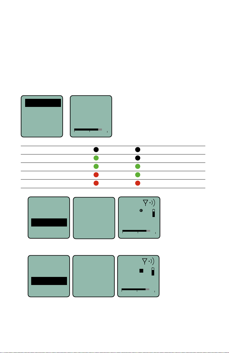
• Have the user talk or sing at the same level that will be used in the
production, and adjust the input gain so that the -20 LED blinks red on
louder peaks
Gain
Gain
Freq.
Rolloff
Compat
Signal Level -20 LED -10 LED
Less than -20 dB
-20 dB to -10 dB
-10 dB to +0 dB
+0 dB to +10 dB
Greater than +10 dB
• Press MENU/SEL and choose Record from the menu
-40
-20
Off Off
Green Off
Green Green
Red Green
Red Red
Files
For mat
Record
RECORD-
ING
Gain
• To stop recording, press MENU/SEL and choose Stop; the word SAVED
appears on the screen
Files
For mat
SAVED
Stop
Gain
Use the UP and DOWN
arrow buttons to adjust
25
the gain until the -20
LED blinks red on
louder peaks
0
b 19
A
E
503.800
-40
b 19
A
E
503.800
-40
REC
-20
-20
0
0
To play back the recordings, remove the memory card and copy the files onto
a computer with video or audio editing software installed.
LECTROSONICS, INC.6
Page 7

SMWB Main Menu
From the Main Window press MENU/SEL.
Use the UP/Down arrow keys to select the item.
Files
SEL
Files
Format
SEL
BACK
BACK
Format?
(erases)
0014A000
0013A000
No
Yes
Select from
listing
Use arrow keys to initiate
formatting the memory card
Use arrow keys to
select file in list
Record
Gain
Freq.
Rolloff
Compat
StepSiz
Phase
TxPower
Sc&Take
Takes
SEL
SEL
SEL
SEL
SEL
SEL
SEL
SEL
SEL
SEL
BACK
BACK
BACK
BACK
BACK
BACK
BACK
BACK
BACK
BACK
RECORD-
Gain
Freq
Rolloff
70 Hz
Compat
Nu Hybrid
StepSiz
Phase
TxPower
Sc&Take
Takes
ING
22
OR
Stop
Select from
listing
b 21
80
550.400
Select from
listing
Select from
listing
Scene 5
Take 3
SEL
BACK
100 kHz
25 kHz
Pos.
Neg.
25mW
50 mW
100 mW
S05 T004
S05 T005
S05 T006
SAVED
Press SEL to
select desired
adjustment
Press SEL to
select desired
adjustment
Use arrow keys to
select input gain
Use arrow keys
to select desired
frequency
Use arrow keys to
select input gain
Use arrow keys to select
compatibility mode
Use arrow keys to select
frequency step size
Use arrow keys to select
audio output polarity
Use arrow keys to select
RF power output
Use arrow keys to
Use arrow keys to select
scene & take
advance scene & take
Naming
SD Info
Default
SEL
SEL
SEL
BACK
BACK
BACK
[SMWB ]
E.........................F
0/ 14G
Max Rec
Default
settings
Seq #
Clock
Battery remaining
Storage used
Storage capacity
Available recording time (H : M : S)
No
Yes
Use arrow keys to select
file naming method
Use arrow keys to return recorder
to default factory settings
Naming
www.lectrosonics.com 7
Page 8

SMWB Power Button Menu
Rf On?
BatType
Remote
Press SEL to return to
the previous screen
SEL
BACK
Use arrow keys to
turn RF signal on/off
No
Yes
Rf On?
SEL
BACK
Use arrow keys to
choose battery type
Alk.
Lith.
BatType
SEL
BACK
Use arrow keys to
enable/disable remote
Enable
Ignore
Remote
From the Main Window press the power button.
Use the UP/DOWN arrow keys to select the item.
Resume
Pwr Off
Press SEL to turn the
power off
AutoOn?
SEL
BACK
ProgSw
Use arrow keys to enable
auto power restore
No
Yes
1.5 V
Backlit
SEL
BACK
Backlit
Use arrow keys to select
LCD backlight duration
On
30 sec
5 sec
Off
About
Locked
SEL
BACK
About
SMWB
v1.00
Displays firmware version
SEL
BACK
Use arrow keys to
lock/unlock keypad
Yes
No
Locked?
LED Off
SEL
BACK
LEDs
Use arrow keys to turn
LEDs on or off
On
Off
Clock
SEL
BACK
Clock
2017
07 / 26
17 : 19
Year
Month / Day
Hour : Minute
LECTROSONICS, INC.8
Page 9

Setup Screen Details
Locking/Unlocking Changes to Settings
Changes to the settings can be locked in the Power Button Menu.
Clock
Locked?
LOCKED
Locked
LED Off
About
When changes are locked, several controls and actions can still be used:
• Settings can still be unlocked
• Menus can still be browsed
• When locked, POWER CAN ONLY BE TURNED OFF by removing the
batteries.
No
Ye s
(menu to
unlock)
Main Window Indicators
The Main Window displays the block number, Standby or Operating mode,
operating frequency, audio level, battery status and programmable switch
function. When the frequency step size is set at 100 kHz, the LCD will look
like the following.
Block number
Frequency
(hex number)
Frequency (MHz)
b 470
2C
474.500
-40
Operating mode
-20
0
Battery status
Audio level
When the frequency step size is set to 25 kHz, the hex number will appear
smaller and may include a fraction.
Fraction
1/4 = .025 MHz
1/2 = .050 MHz
3/4 = .075 MHz
www.lectrosonics.com 9
b 470
1
2C
4
474.525
-40
-20
Note that the
frequency has
increased by 25
kHz from the upper
example.
0
Page 10

Changing the step size never changes the frequency. It only changes the way
the user interface works. If the frequency is set to a fractional increment between even 100 kHz steps and the step size is changed to 100 kHz, the hex
code will be replaced by two asterisks on the main screen and the frequency
screen.
Frequency set to fractional 25 kHz step,
but step size changed to 100 kHz.
b 19
Freq.
b 19
494.525
-40
-20
0
494.525
Connecting the Signal Source
Microphones, line level audio sources and instruments can be used with
the transmitter. Refer to the manual section entitled Input Jack Wiring for
Different Sources for details on the correct wiring for line level sources and
microphones to take full advantage of the Servo Bias circuitry.
Turning Control Panel LEDs ON/OFF
From the main menu screen, a quick press of the UP arrow button turns the
control panel LEDs on. A quick press of the DOWN arrow button turns them
off. The buttons will be disabled if the LOCKED option is selected in the Power
Button menu.
The control panel LEDs can also be turned on and off with the LED Off option
in the Power Button menu.
Helpful Features on Receivers
To aid in finding clear frequencies, several Lectrosonics receivers offer a
SmartTune feature that scans the tuning range of the receiver and displays a
graphical report that shows where RF signals are present at different levels,
and areas where there is little or no RF energy present. The software then
automatically selects the best channel for operation.
Lectrosonics receivers equipped with an IR Sync function allow the receiver
to set frequency, step size and compatibility modes on the transmitter via an
infrared link between the two units.
Files
Files
For mat
Record
Gain
Select recorded
Files
0007A000
0006A000
0005A000
0004A000
0003A000
0002A000
LECTROSONICS, INC.10
files on
microSDHC
memory card.
Page 11

Format
Files
For mat
Record
Gain
Formats the microSDHC memory card.
WARNING: This function erases any content on the
microSDHC memory card.
Record or Stop
Begins recording or stops recording. (See page 7.)
Adjusting the Input Gain
The two bicolor Modulation LEDs on the control panel provide a visual indication of the audio signal level entering the transmitter. The LEDs will glow either
red or green to indicate modulation levels as shown in the following table.
Signal Level -20 LED -10 LED
Less than -20 dB
-20 dB to -10 dB
-10 dB to +0 dB
+0 dB to +10 dB
Greater than +10 dB
NOTE: Full modulation is achieved at 0 dB, when the “-20” LED first
turns red. The limiter can cleanly handle peaks up to 30 dB above this
point.
It is best to go through the following procedure with the transmitter in the
standby mode so that no audio will enter the sound system or recorder during
adjustment.
1) With fresh batteries in the transmitter, power the unit on in the standby
mode (see previous section Turning Power ON and OFF).
2) Navigate to the Gain setup screen.
Off Off
Green Off
Green Green
Red Green
Red Red
Gain
Freq
Gain
25
Rolloff
Compat
3) Prepare the signal source. Position a microphone the way it will be used
in actual operation and have the user speak or sing at the loudest level
that will occur during use, or set the output level of the instrument or
audio device to the maximum level that will be used.
www.lectrosonics.com 11
-40
-20
0
Page 12

4) Use the and arrow buttons to adjust the gain until the –10 dB glows
green and the –20 dB LED starts to flicker red during the loudest peaks
in the audio.
5) Once the audio gain has been set, the signal can be sent through the
sound system for overall level adjustments, monitor settings, etc.
6) If the audio output level of the receiver is too high or low, use only the
controls on the receiver to make adjustments. Always leave the transmitter gain adjustment set according to these instructions, and do not
change it to adjust the audio output level of the receiver.
Selecting Frequency
The setup screen for frequency selection offers several ways to browse the
available frequencies.
Gain
Freq
Rolloff
Compat
Each field will step through the available frequencies in a different increment.
The increments are also different in the 25 kHz mode from the 100 kHz mode.
Freq.
b 19
494.500
51
Press MENU/
SEL to select
one of four
fields to make
adjustments
Freq.
b 19
51
494.500
These two fields step in 25 kHz
increments when the step size is 25
Freq.
b 19
kHz and 100 kHz increments when
the step size is 100 kHz.
51
494.500
Freq.
b 19
51
These two fields
always step in the
same increments
1 block steps
Freq.
b 19
51
494.500
LECTROSONICS, INC.12
1 MHz steps
494.500
Page 13

A fraction will appear next to the hex code in the setup screen and in the main
window when the frequency ends in .025, .050 or .075 MHz.
Freq.
b 19
494.525
51
Fraction appears
next to hex code
1
in 25 kHz mode
4
b 470
1
51
4
474.525
-40
-20
0
Selecting Frequency Using Two Buttons
Hold the MENU/SEL button in, then use the and arrow buttons for alternate increments.
NOTE: You must be in the FREQ menu to access this feature. It is not
available from the main/home screen.
1 block steps
1.6 MHz steps to
nearest 100 kHz
channel
100 kHz steps
to next 100 kHz
channel
10 MHz steps
100 kHz Mode
Freq.
b 19
51
494.500
25 kHz Mode
Freq.
b 19
1
51
10 MHz steps
4
494.525
If the Step Size is 25 kHz with the frequency set between even 100 kHz steps
and the Step Size is then changed to 100 kHz, the mismatch will cause the
hex code to display as two asterisks.
Freq.
b 19
Step Size and
Frequency
mismatch
**
494.500
www.lectrosonics.com 13
1 block steps
1.6 MHz steps
25 kHz steps
b 19
494.525
-40
-20
0
Page 14

About Overlapping Frequency Bands
When two frequency bands overlap, it is possible to select the same frequency at the upper end of one and the lower end of the other. While the frequency
will be the same, the pilot tones will be different, as indicated by the hex
codes that appear.
In the following examples, the frequency is set to 494.500 MHz, but one is
in band 470 and the other in band 19. This is done intentionally to maintain
compatibility with receivers that tune across a single band. The band number
and hex code must match the receiver to enable the correct pilot tone.
Freq.
b 19
51
494.500
Freq.
b470
494.500
band number and
hex code match
the receiver setting
F4
Make sure the
Selecting the Low Frequency Roll-off
It is possible that the low frequency roll-off point could affect the gain setting,
so it’s generally good practice to make this adjustment before adjusting the
input gain. The point at which the roll-off takes place can be set to:
• LF 35 35 Hz
• LF 50 50 Hz
• LF 70 70 Hz
• LF 100 100 Hz
• LF 120 120 Hz
• LF 150 150 Hz
The roll-off is often adjusted by ear while monitoring the audio.
Rolloff
Compat
StepSiz
Phase
Rolloff
70 Hz
LECTROSONICS, INC.14
Page 15

Selecting the Compatibility (Compat) Mode
Rolloff
Compat
Compat
StepSiz
IFB
Phase
Use the UP and DOWN arrows to select the desired mode, then press the
BACK button twice to return to the Main Window.
Compatibility modes are as follows:
Receiver Models LCD menu item
SMWB/SMDWB:
• Nu Hybrid: Nu Hybrid
• Mode 3:* Mode 3
• IFB Series: IFB Mode
Mode 3 works with certain non-Lectrosonics models. Contact the factory for
details.
NOTE: If your Lectrosonics receiver does not have Nu Hybrid mode,
set the receiver to Euro Digital Hybrid Wireless® (EU Dig. Hybrid).
/E01:
®
• Digital Hybrid Wireless
• Mode 3: Mode 3*
• IFB Series: IFB Mode
* Mode works with certain non-Lectrosonics models. Contact the factory for
details.
/X:
• Digital Hybrid Wireless
• Mode 3:* Mode 3
• 200 Series: 200 Mode
• 100 Series: 100 Mode
• Mode 6:* Mode 6
• Mode 7:* Mode 7
• IFB Series: IFB Mode
Modes 3, 6 and 7 work with certain non-Lectrosonics models. Contact the
factory for details.
: EU Hybr
®
: NA Hybr
www.lectrosonics.com 15
Page 16

Selecting Step Size
This menu item allows frequencies to be selected in either 100 kHz or 25 kHz
increments.
Rolloff
StepSiz
StepSiz
Compat
StepSiz
Phase
If the desired frequency ends in .025, .050 or .075 MHz, the 25 kHz step size
must be selected.
Normally, the receiver is used to find a clear operating frequency. All Lectrosonics Digital Hybrid Wireless
ly and easily find prospective frequencies with little or no RF interference. In
other cases, a frequency may be specified by officials at a large event such as
the Olympics or a major league ball game. Once the frequency is determined,
set the transmitter to match the associated receiver.
100 kHz
25 kHz
®
receivers provide a scanning function to quick-
100 kHz
25 kHz
Selecting Audio Polarity (Phase)
Audio polarity can be inverted at the transmitter so the audio can be mixed
with other microphones without comb filtering. The polarity can also be inverted at the receiver outputs.
Rolloff
Phase
Compat
StepSiz
Phase
Pos.
Neg.
Setting Transmitter Output Power
The output power can be set to:
SMWB/SMDWB, /X
• 25, 50 or 100 mW
/E01
• 10, 25 or 50 mW
Compat
StepSiz
Phase
TxPower
LECTROSONICS, INC.16
TxPower
25 mW
50 mW
100 mW
Page 17

Setting Scene and Take Number
Use UP and DOWN arrows to advance Scene and Take and MENU/SEL to
toggle. Press the BACK button to return to menu.
TxPower
Sc&Take
Sc&Take
Ta kes
Scene 1
Ta ke 5
Naming
Choosing Takes for Replay
Use UP and DOWN arrows to toggle and MENU/SEL to play back.
TxPower
Sc&Take
Ta kes
Naming
Ta kes
S01 T001
S01 T002
S02 T001
S03 T001
Recorded File Naming
Choose to name the recorded files by the sequence number or by the clock
time.
TxPower
Sc&Take
Ta kes
Naming
Naming
Seq #
Clock
MicroSDHC Memory Card Info
MicroSDHC Memory Card information including space remaining on card.
Fuel gauge
Storage used
Storage capacity
Available recording
time (H : M : S)
Ta kes
Naming
SD Info
Default
[SMWB ]
E.........................F
0/ 14G
Max Rec
Restoring Default Settings
This is used to restore the factory settings.
www.lectrosonics.com 17
Page 18

Compatibility with microSDHC
memory cards
Please note that the PDR and SPDR are designed for use with the microSDHC memory cards. There are several types of SD card standards (as of this
writing) based on capacity (storage in GB).
SDSC: standard capacity, up to and including 2 GB – DO NOT USE!
SDHC: high capacity, more than 2 GB and up to and including 32 GB – USE
THIS TYPE.
SDXC: extended capacity, more than 32 GB and up to and including 2 TB –
DO NOT USE!
SDUC: extended capacity, more than 2TB and up to and including 128 TB –
DO NOT USE!
The larger XC and UC cards use a different formatting method and bus structure and are NOT compatible with the SPDR recorder. These are typically
used with later generation video systems and cameras for image applications
(video and high resolution, high speed photography).
ONLY the microSDHC memory cards should be used. They are available in
capacities from 4GB to 32GB. Look for the Speed Class 10 cards (as indicated by a C wrapped around the number 10), or the UHS Speed Class I cards
(as indicated by the numeral 1 inside a U symbol). Also note the microSDHC
Logo.
If you are switching to a new brand or source of card, we always suggest testing first before using the card on a critical application.
The following markings will appear on compatible memory cards. One or all of
the markings will appear on the card housing and the packaging.
Speed Class 10
UHS Speed Class 1
UHS Speed Class I
microSDHC Logo is a trademark of SD-3C, LLC
LECTROSONICS, INC.18
Stand-alone
UHS Speed Class I
Accompanying
microSDHC logo
Page 19

Formatting SD Card
New microSDHC memory cards come pre-formatted with a FAT32 file system
which is optimized for good performance. The PDR relies on this performance
and will never disturb the underlying low level formatting of the SD card. When
the SMWB/SMDWB “formats” a card, it performs a function similar to the
Windows “Quick Format” which deletes all files and prepares the card for recording. The card can be read by any standard computer but if any write, edit
or deletions are made to the card by the computer, the card must be re-formatted with the SMWB/SMDWB to prepare it again for recording. The SMWB/
SMDWB never low level formats a card and we strongly advise against doing
so with the computer.
To format the card with the SMWB/SMDWB, select Format Card in the menu
and press MENU/SEL on the keypad.
NOTE: An error message will appear if samples are lost due to a poor
performing “slow” card.
WARNING: Do not perform a low level format (complete format) with a
computer. Doing so may render the memory card unusable with the SMWB/
SMDWB recorder.
With a windows based computer, be sure to check the quick format box before
formatting the card.
With a Mac, choose MS-DOS (FAT).
IMPORTANT
The formatting of the SD card sets up contiguous sectors for maximum efficiency in the recording process. The file format utilizes the BEXT (Broadcast
Extension) wave format which has sufficient data space in the header for the
file information and the time code imprint.
The SD card, as formatted by the SMWB/SMDWB recorder, can be corrupted
by any attempt to directly edit, change, format or view the files on a computer.
The simplest way to prevent data corruption is to copy the .wav files from the
card to a computer or other Windows or OS formatted media FIRST. Repeat
– COPY THE FILES FIRST!
Do not rename files directly on the SD card.
Do not attempt to edit the files directly on the SD card.
Do not save ANYTHING to the SD card with a computer (such as the take
log, note files etc) - it is formatted for SMWB/SMDWB recorder use only.
Do not open the files on the SD card with any third party program such as
Wave Agent or Audacity and permit a save. In Wave Agent, do not IMPORT you can OPEN and play it but do not save or Import - Wave Agent will corrupt
the file.
In short - there should be NO manipulation of the data on the card or addition of data to the card with anything other than an SMWB/SMDWB recorder. Copy the files to a computer, thumb drive, hard drive, etc. that has been
formatted as a regular OS device FIRST - then you can edit freely.
iXML HEADER SUPPORT
Recordings contain industry standard iXML chunks in the file headers, with
the most commonly used fields filled in.
www.lectrosonics.com 19
Page 20

 Loading...