

Lectrosonics SMDB/E01 Series, SMB/E01 Instruction Manual
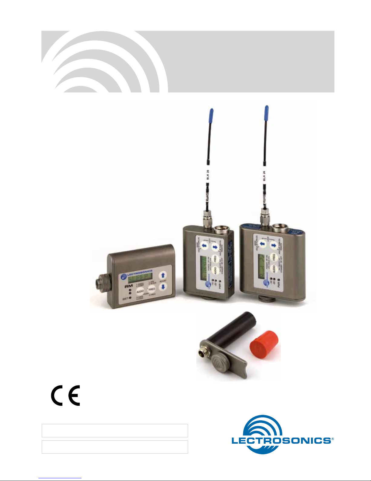
SMB/E01Series
Super Miniature Transmitters
With Digital Hybrid Wireless® Technology
SMDB/E01 Dual battery
SMB/E01 Single battery
RM/E Remote Control
SMBATELIM Battery eliminator
INSTRUCTION MANUAL
Fill in for your records:
Serial Number:
Purchase Date:
Rio Rancho, NM, USA
www.lectrosonics.com
US Patent 7,225,135

SMB/EO1 Series
LECTROSONICS, INC.
2
Table of Contents
Introduction ...................................................................................................................................................................................... 3
General Technical Description ....................................................................................................................................................... 4
Servo Bias Input............................................................................................................................................................................. 4
No Pre-Emphasis/De-Emphasis .................................................................................................................................................... 4
Low Frequency Roll-Off ................................................................................................................................................................. 4
Input Limiter ................................................................................................................................................................................... 4
Signal Encoding and Pilot Tone ..................................................................................................................................................... 5
Microprocessor Control .................................................................................................................................................................. 5
Compatibility Modes ....................................................................................................................................................................... 5
Control Panel ................................................................................................................................................................................. 5
Battery Options and Operating Time ............................................................................................................................................. 5
Frequency Blocks ........................................................................................................................................................................... 5
Circulator/Isolator ........................................................................................................................................................................... 5
Controls and Functions .................................................................................................................................................................. 6
LCD Screen ................................................................................................................................................................................... 6
Power LED ..................................................................................................................................................................................... 6
Audio Input Jack ............................................................................................................................................................................. 6
AUDIO Button ................................................................................................................................................................................ 6
FREQ Button .................................................................................................................................................................................. 6
Up/Down Arrows ............................................................................................................................................................................ 6
Antenna .......................................................................................................................................................................................... 6
Setup Screens .................................................................................................................................................................................. 7
Audio Screen ................................................................................................................................................................................. 7
Frequency Screen .......................................................................................................................................................................... 7
Lock/Unlock Screen ....................................................................................................................................................................... 7
Remote Control Operation ............................................................................................................................................................. 7
Configuring for Power Restore ....................................................................................................................................................... 7
Battery and Battery Eliminator Installation ................................................................................................................................... 8
Operating Instructions .................................................................................................................................................................... 8
Power Up and Boot Sequence ....................................................................................................................................................... 8
Power Down ................................................................................................................................................................................... 8
Standby Mode ................................................................................................................................................................................ 9
Selecting the Compatibility Mode ................................................................................................................................................... 9
Setting Transmitter Operating Frequency ....................................................................................................................................... 9
5-Pin Input Jack Wiring ................................................................................................................................................................. 10
Installing the Connector: .............................................................................................................................................................. 10
Microphone Cable Termination for Non-Lectrosonics Microphones ........................................................................................11
Microphone RF Bypassing ........................................................................................................................................................... 12
Line Level Signals ........................................................................................................................................................................ 12
Wiring Hookups for Different Sources ........................................................................................................................................ 13
Compatible Wiring for Both Servo Bias Inputs and Earlier Transmitters: ..................................................................................... 13
Simple Wiring - Can ONLY be used with Servo Bias Inputs: ........................................................................................................ 13
Optional RM/E Remote Control .................................................................................................................................................... 14
Powering the RM on and off ......................................................................................................................................................... 14
Setup Screens ............................................................................................................................................................................. 14
Operating Notes ........................................................................................................................................................................... 15
RM Quick Reference .................................................................................................................................................................... 15
Troubleshooting ............................................................................................................................................................................. 16
RM Troubleshooting ..................................................................................................................................................................... 17
Straight Whip Antennas ................................................................................................................................................................ 18
Included Accessories .................................................................................................................................................................... 19
Optional Accessories .................................................................................................................................................................... 19
Adjusting Audio Level (Gain) ........................................................................................................................................................ 20
Locking or Unlocking the Controls ............................................................................................................................................... 20
Attaching and Removing the Microphone .................................................................................................................................... 20
Specifications and Features ......................................................................................................................................................... 21
Service and Repair ........................................................................................................................................................................ 23
Returning Units for Repair ........................................................................................................................................................... 23

Super-Minature Belt Pack Transmitters
Rio Rancho, NM
3
Introduction
The SMB Series transmitters are the product of many
years of engineering and experience in professional
audio markets. The unique design provides several
distinct features for professional applications:
• Superb,compandor-freeaudioquality
• Ultra-lightweight,corrosionresistanthousing
• Waterresistantsealsforuseindampenviron-
ments
• Programmablecompatibilitymodesforusewitha
wide variety of different receivers
The Digital Hybrid Wireless® design (US Patent
7,225,135) combines 24-bit digital audio with analog
FM resulting in a system that has the same operating
range as analog systems, the same spectral efficiency as analog systems, the same long battery life
as analog systems, plus the excellent audio fidelity
typical of pure digital systems.
The transmitters feature the unique servo bias input
circuitry with a standard TA5M type input jack for use
with electret lavaliere mics, dynamic mics, or line level
signals. A water resistant control panel with LCD,
membrane switches and multi-color LEDs make input
gain adjustments, frequency and compatibility mode
selection quick and accurate, without having to view
the receiver. The battery compartment accepts AA
lithium or rechargeable batteries. The housings are
machined from solid aluminum blocks to provide an
extremely lightweight and rugged package. A special
non-corrosive finish resists salt water exposure and
perspiration in extreme environments.
The DSP-based design works with Euro version Digital Hybrid and IFB receivers.

SMB/EO1 Series
LECTROSONICS, INC.
4
Variable 1.8 - 4v
+6V
+5V
5V
Regulator
Servo Bias Input
The voltage and current requirements of the wide
variety of electret microphones used in professional
applications has caused confusion and compromises
in the wiring needed for wireless transmitters. To address this problem, the unique Servo Bias input circuit
provides an automatically regulated voltage over a
very wide range of current for compatibility with all
microphones.
Digital Hybrid Wireless® Technology
All wireless links suffer from channel noise to some
degree, and all wireless microphone systems seek to
minimize the impact of that noise on the desired signal. Conventional analog systems use compandors for
enhanced dynamic range, at the cost of subtle artifacts
(typically “pumping” and “breathing”). Wholly digital systems defeat the noise by sending the audio information
in digital form, at the cost of some combination of power,
bandwidth and resistance to interference.
Digital Hybrid systems overcome channel noise in
a dramatically new way, digitally encoding the audio
in the transmitter and decoding it in the receiver, yet
still sending the encoded information via an analog
FM wireless link. This proprietary algorithm is not a
digital implementation of an analog compandor but a
technique that can be accomplished only in the digital
domain, even though the inputs and outputs are
analog.
Because it uses an analog FM link, the Digital Hybrid
system enjoys all the benefits of conventional FM
wireless systems and it does away with the analog
compandor and its artifacts.
General Technical Description
No Pre-Emphasis/De-Emphasis
The Digital Hybrid design results in a signal-to-noise
ratio high enough to preclude the need for conventional
pre-emphasis (HF boost) in the transmitter and deemphasis (HF roll off) in the receiver. This eliminates
the potential for distortion of signals with abundant
high-frequency information.
Low Frequency Roll-Off
The low frequency roll-off can be set for a 3 dB down
point at 35, 50, 70, 100, 120 and 150 Hz to control
subsonic and very low frequency audio content in
the audio. The actual roll-off frequency will vary slightly
depending upon the low frequency response of the
microphone.
Excessive low frequency content can drive the transmitter into limiting, or in the case of high level sound
systems, can even cause damage to loudspeaker
systems. The roll-off is normally adjusted by ear
while listening as the system is operating.
Input Limiter
A DSP-controlled analog audio limiter is employed
before the A-D converter. The limiter has a range of
more than 30 dB for excellent overload protection. A
dual release envelope makes the limiter acoustically
transparent while maintaining low distortion. It can be
thought of as two limiters in series, a fast attack and
release limiter followed by a slow attack and release
limiter. The limiter recovers quickly from brief transients, with no audible side effects, and also recovers slowly from sustained high levels to keep audio
distortion low while preserving short term dynamics.

Super-Minature Belt Pack Transmitters
Rio Rancho, NM
5
Signal Encoding and Pilot Tone
In addition to controlling the limiter, the DSP also encodes the digitized audio from the A/D converter and
adds an ultrasonic pilot tone to control the squelch
in the receiver. A pilot tone squelch system provides a
reliable method of keeping a receiver output muted
when the squelch is active, even in the presence of
significant interference. When the system is operating
in the hybrid mode, a different pilot tone frequency
is generated for each carrier frequency to prevent
squelch problems in multi-channel systems.
Microprocessor Control
A microprocessor monitors user command inputs
from the control panel buttons and numerous other
internal signals. It works intimately with the DSP to
ensure the audio is encoded according to the selected Compatibility Mode and that the correct pilot tone
is added to the encoded signal.
Compatibility Modes
SMB transmitters are designed to operate with Lectrosonics Digital Hybrid receivers and will yield the
best performance when doing so, however, due to the
flexibility of digital signal processing, they can also
operate with Lectrosonics Euro version IFB receivers.
Control Panel
The control panel includes four membrane switches and
an LCD screen to adjust the operational settings. Multicolor LEDs are used to indicate audio signal levels for
accurate gain adjustment and for battery status.
Battery Options and Operating Time
Switching power supplies convert regulated battery
voltages to operate various circuit stages with maximum efficiency. With the variety of alkaline, lithium
and rechargeable NiMH batteries available today in
the AA format, there are many choices to maximize
operating time or minimize cost as needed for any
application.
The firmware “remembers” the power status when a
battery fails or power is disconnected, so the transmitter will be turned on automatically when power is
restored and previous settings will be enabled.
Frequency Blocks
Lectrosonics established a “block” numbering system
years ago to organize the range of frequencies that
are available. Legacy transmitters and receivers used
two binary switches, each with 16 positions, to set the
operating frequency. 16 x 16 = 256, which defined the
standard number of frequencies in each block to be
256. Since the steps between frequencies is 100 kHz,
this results in a switching range of 25.6 MHz.
The lowest frequency in the switching range divided by 25.6 yields the block number. For example,
640.000 divided by 25.6 equals 25. In other words,
block 25 starts at 640.000 MHz.
To determine what block a particular frequency falls
into, divide the frequency and use the two significant
digits to the left of the decimal. For example, to calculate the block for 580.500 MHz, divide 580 by 25.6,
which equals 22.656, which indicates block 22.
Circulator/Isolator
The RF output circuit includes a one way circulator/
isolator using a magnetically polarized ferrite. This
device greatly reduces RF intermodulation produced
when multiple transmitters are used in close proximity
to one another (a meter or two, or less). The isolator
also protects the output amplifier against static shock.

SMB/EO1 Series
LECTROSONICS, INC.
6
Controls and Functions
LCD Screen
The LCD is a numeric-type Liquid Crystal Display with
screens for adjusting power, frequency, audio level
and low frequency audio roll-off. The transmitter can
be powered up with or without the RF output turned
on. A countdown appears in the LCD when powering
on and off, allowing the transmitter to be turned on
without RF for adjustments, and to prevent accidentally turning it off with momentary button presses.
Power LED
The PWR LED glows green when the battery is good.
The color changes to red at a mid-point of operating
life, and will continue to glow red until the battery gets
close to the end of its life. When the LED begins to
blink red, there are only a few minutes remaining.
The exact point at which the LED turns red will vary
with battery brand and condition, temperature and
current drain. The LED is simply a reminder intended
to catch your attention, not an exact indicator of remaining time.
1.6
1.4
1.2
1.0
.8
2468
Hours
Voltage
Varies
Green Red Blink
Example of AA lithium battery in SMB transmitter
A NiMH rechargeable battery will give little or no
warning when it is depleted because the voltage does
not vary much during its operating life. If you wish
to use NiMH batteries, we recommend trying fully
charged batteries in the unit and using the battery
timer feature available in most receivers to determine
the available operating time.
A weak battery will sometimes cause the PWR LED
to glow green immediately after the transmitter is
turned on, but the battery will soon discharge to the
point where the LED will turn red or the unit will turn
off completely. When the transmitter is in SLEEP
mode, the LED blinks green every few seconds.
Audio Input Jack
The Servo Bias input circuitry accommodates virtually every lavaliere, handheld or shotgun microphone
available, plus line level signals.
Modulation LEDs
Proper input gain adjustment is critical to ensure the
best audio quality. Two bicolor LEDs will glow either
red or green to accurately indicate modulation levels.
The input circuitry includes a wide range DSP controlled limiter to prevent distortion at high input levels.
It is important to set the gain (audio level) high
enough to achieve full modulation during louder peaks
in the audio. The limiter can handle over 30 dB of level
above full modulation, so with an optimum setting,
the LEDs will flash red during use. If the LEDs never
flash red, the gain is too low. In the table below, +0 dB
indicates full modulation.
Signal Level -20 LED -10 LED
Less than -20 dB Off Off
-20 dB to -10 dB Green Off
-10 dB to +0 dB
Green Green
+0 dB to +10 dB
Red Green
Greater than +10 db
Red Red
AUDIO Button
The AUDIO button is used to display the audio level
and low frequency roll-off settings. The UP and
DOWN arrows adjust the values.
The AUDIO button is also used with the FREQ button to
enter standby mode and to turn the transmitter on or off.
FREQ Button
The FREQ Button displays the selected operating frequency and also toggles the LCD between displaying
the actual operating frequency in MHz and a two-digit
hexadecimal number that corresponds to the equivalent Lectrosonics Frequency Switch Setting.
The FREQ button is also used with the AUDIO button to
enter standby mode and to turn the transmitter on or off.
Up/Down Arrows
The Up and Down arrow buttons are used to select
the values on the various setup screens and to lock
out the control panel. Pressing both arrows simultaneously enters the lock countdown. When an attempt is
made to change a setting while the control panel is
locked, a message will flash on the LCD reminding
you that the unit is locked. Once locked, the buttons
can only be unlocked by removing the battery, or via
the RM remote control (if the remote function was
enabled in the transmitter setup).
Antenna
The transmitter uses a whip antenna with a flexible
woven, galvanized steel mesh cable and a standard
SMA connector.
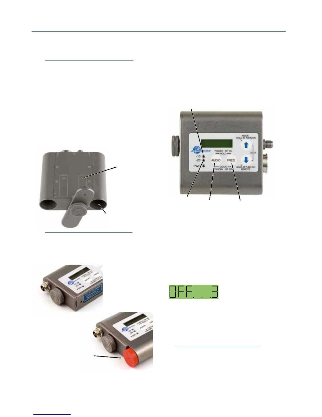
Battery
Compartment
Retaining
Screw
Battery
Compartment
Cover Plate
Audio
Input Jack
AUDIO Button
LCD
FREQ Button
Modulation
LEDs
PWR LED
UP Arrow
DOWN Arrow
Antenna
Jack

Super-Minature Belt Pack Transmitters
Rio Rancho, NM
7
Setup Screens
Audio Screen
The Audio screen is used
to adjust input gain from 0
to +44 dB, and the low
frequency roll-off from 35
to 150 Hz. Repeatedly
pressing the AUDIO
button toggles back and
forth between the two
displays. Press and hold the AUDIO button and use
the Up and Down arrows to make adjustments.
Frequency Screen
The Frequency Screen
displays the operating
frequency in MHz or as a
two-digit hexadecimal
number that corresponds
to the equivalent Lectro-
sonics Frequency Switch
Setting. Repeatedly
pressing the FREQ button toggles between the two
displays. Press and hold the FREQ button and use
the Up and Down arrows to select the frequency.
Lock/Unlock Screen
Simultaneously pressing
and holding both the Up
and Down arrow buttons
during normal operation
starts the Lock timer. The
timer starts at three and
counts down to zero.
When the timer reaches zero, the transmitter’s
controls are locked.
With the controls locked, the AUDIO and FREQ buttons can still be used to display current settings. Any
attempt to change a setting by pressing either the Up
or Down arrow button will result in an on-screen Loc
reminder that the controls are locked. Remove the
batteries to unlock the control panel.
Important: Once the transmitter is locked, it
cannot be unlocked or powered off using the
buttons. The only ways to unlock a locked
transmitter are to remove the battery or unlock
it using the RM remote control if this function is
enabled on the transmitter.
Remote Control Operation
Remote Control Screens
The transmitters can be
configured to respond to
signals from the RM
remote control unit or to
ignore them. This setting
is accessed by holding
down the Down arrow
button while powering the
transmitter on.
If a remote control signal is detected but the transmitter is set to rc oFF, the message rc oFF will be
displayed briefly on the transmitter’s LCD, to confirm
that a valid signal was received, but that the transmitter is not configured to respond to it.
Functions available from the remote control are:
• AudioLevel
• Frequency
• Lock/UnlockButtons
• Sleep/Wake(powersavingmode)
In sleep mode, the transmitter uses only 20% of the
normal amount of battery drain. Sleep mode can only
be invoked with the remote control, and can only be
revoked with the remote control or by removing the
battery. When in the sleep mode, the PWR LED blinks
green every few seconds to indicate that the transmitter
is asleep and not turned off.
The RM is not included with SM Series transmitters.
Several “Dweedle tones” can also be downloaded
from the web site at:
http://www.lectrosonics.com/europe/en/Transmitters/
rm.html
The dweedle tones can be played back through an
MP3 player, PDA, smart phone, etc., and in most
cases, will even work with walkie talkies. The tones
will not work through the loudspeakers of a sound
system because the reflections and reverberation in
the room will alter the tones.
Configuring for Power Restore
Power Restore Screens
The Power Restore feature
will turn the transmitter
back on with the same
settings that were enabled
in the previous use after a
battery is replaced or
external power has been
cycled off and back on.
1) Press and hold the Down Arrow Button then
power on the transmitter by pressing the
Audio and Freq buttons simultaneously.
2) Press AUDIO or FREQ key to scroll to the setting
and then use the arrow keys to select PbAc 1 for
ON or PbAc 0 for OFF.
SMB/EO1 Series
LECTROSONICS, INC.
8
Operating Instructions
Power Up and Boot Sequence
1) Ensure that good batteries are installed in the
unit.
2) Simultaneously press and hold the AUDIO and
FREQ buttons until the Power On Boot Sequence
is initiated. As the unit turns on, the Modulation
LEDs and PWR LED all glow red, then green, and
then revert to normal operation.
AUDIO
Button
FREQ
Button
Modulation LEDs
PWR LED
The LCD displays a bootup sequence which con-
sists of four screens similar to these examples:
Company Name: Lectro
Frequency Block (bXX) and
Firmware Version (rX.X): b21r1.1
Power Level Pr 50
Compatibility Mode: CP Hbr
Audio: Aud 22
Power Down
Initial Power Off
Timer Screen
1) Simultaneously press and hold the AUDIO and
FREQ buttons while observing that the word OFF
appears in the LCD along with a counter.
2) Continue holding the buttons in until the counter
reaches 0, and the unit will then turn off.
Note: If the AUDIO and FREQ buttons are
released before the LCD goes blank at the
end of the countdown, the unit will not turn off.
Instead, it will stay energized and the display will
return to the previous screen.
Battery and Battery
Eliminator Installation
Note: Standard zinc-carbon batteries marked
“heavy-duty” or “long-lasting” are not
adequate.
The battery status circuitry is designed for the voltage
drop over the life of lithium batteries.
To install new batteries:
1. Turn the Battery Cover Plate Thumbscrew counterclockwise a few turns until the door will rotate.
2. Insert the new batteries into the housing. The
positive (+) battery terminal goes into the
transmitter first.
3. Align the Battery Cover Plate and tighten the Battery Cover Plate Thumbscrew.
Insert (+) tip first
on both models
Polarity is
shown on the
back cover
of the dual
battery model
NOTE: Refer to the previous section entitled
Configuring for Power Restore
To install the battery eliminator, loosen the thumbscrew completely and remove the battery door. Insert
the battery eliminator and tighten the thumbscrew.
Install plastic cap on dual
battery model to cover the
open battery compartment.
 Loading...