

Page 1

R5
UHF MULTI-FREQUENCY
BELT-PACK IFB RECEIVER
EURO MODEL
OPERATING INSTRUCTIONS
and trouble-shooting guide
LECTROSONICS, INC.
www.lectrosonics.com
0885
Page 2

INTRODUCTION
Thank you for selecting the Lectrosonics frequency agile, R5 IFB Receiver. The R5
is the result of extensive engineering experience with the very latest components.
The design addresses the most demanding professional applications.
The Lectrosonics R5 Receiver along with the companion T5 transmitter allow on-air
talent to monitor program audio, and to receive cues from directors and other
production personnel.
The R5 Receiver is housed in a rugged, machined aluminum package for lasting
performance in abusive environments
Only the R5 IFB Receiver is covered in this manual. The companion T5 transmitter is
covered in a separate manual. The R5 IFB Receiver will operate with any Lectrosonics T5 IFB Transmitter in the same frequency block.
TABLE OF CONTENTS
INTRODUCTION .................................................................................................. 2
GENERAL TECHNICAL DESCRIPTION ............................................................ 3
SAFETY NOTES .................................................................................................. 5
RECEIVER OPERATING INSTRUCTIONS ........................................................ 6
BATTERY INSTRUCTIONS ................................................................................. 7
TROUBLESHOOTING ......................................................................................... 8
SPECIFICATIONS AND FEATURES................................................................... 9
2
Page 3

IFB Receiver
GENERAL TECHNICAL DESCRIPTION
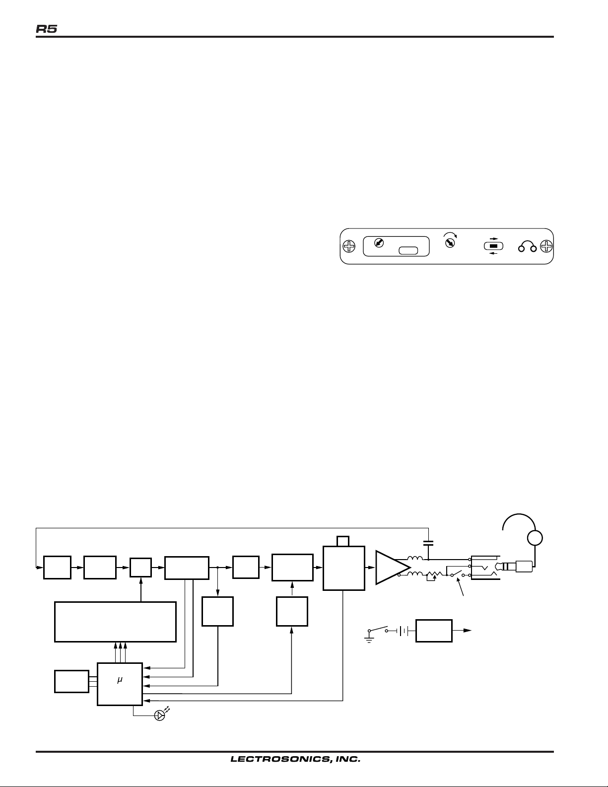
The IFB R5 Receiver is comprised of a number of functional subsystems as shown in Fig 1, Control Panel and Fig
3, Receiver Block Diagram.
GENERAL FEATURES
The frequency agile IFB R5 FM Receiver is designed to operate with the Lectrosonics IFB T5 Transmitter and
features microprocessor control of 256 frequencies of operation within each frequency block. Each block covers 25.5
MHz with 0.100 MHz frequency spacing. Up to 256 special frequencies and 0.025MHz spacing can be programmed
into a unit by the factory or by authorized service centers. Any one of thirteen different frequency blocks numbered
21 through 33 are factory available from 537.6 MHz to 865.0 MHz.
The receiver’s unique microcontroller design provides simple one knob and one LED operation for audio level,
switching channels, and easy on-the-fly programming. A nonvolatile memory “remembers” all stored channels during
power OFF and returns operation to the last channel used when powered ON.
The IFB R5 Receiver uses 20 kHz FM deviation for efficient use of the bandwidth and a single band compandor for
clean quiet audio.
The Pilot Tone squelch locks the reception to the mating IFB T5 Transmitter and ignores other signals.
The receiver operates on one 9 Volt alkaline battery for up to 8 hours and features a blinking LED low battery indicator. The voltages are internally regulated for stability.
The receiver is housed in a compact, rugged, lightweight aluminum enclosure. The unit features a durable removable
belt clip and an integral swing-aside battery compartment door.
CONTROL KNOB (fig. 1)
The single front panel control knob performs multiple functions;
1. Rotate for Power ON/OFF 3. Push quick, Channel Switching
2. Rotate for Audio Level 4. Push and rotate for Scan and Channel programming,
SCAN
(PUSH)
OFF MAX
AUDIO
LEVEL
LECTRO
IFB RECEIVER
R5
Figure 1 - R5 Control Panel
Refer to the RECEIVER OPERATING INSTRUCTIONS for full details on how to use the single knob control for
channel selection, scanning, and programming of the five memory locations.
LED INDICATOR (fig. 1)
The LED indicator on the front panel also indicates multiple functions.
CHANNEL NUMBER - The LED will blink OFF a number of times corresponding to the Channel Number when the
unit is switched ON and also when a new frequency is added to an open channel. For example, for channel 3 the
LED would blink OFF three times. After blinking the channel number the LED will return to a steady ON indicating
normal operation.
BATTERY STATUS - During normal operation a steady ON LED indicates a good battery. When the battery is nearly
exhausted the LED will blink one long and two short blinks. Continued use will further deplete the battery causing
the unit to automatically turn itself OFF until a fresh battery is installed.
PROGRAMMING FUNCTIONS - In the programming mode, the LED will blink at a fast rate to indicate scanning for
an active frequency. It also flashes briefly to indicate a frequency has been programmed into a channel.
Rio Rancho, NM – USA
3
Page 4
HEADPHONE JACK (fig. 1)
On the front panel is a 3.5mm mini phone jack to accommodate a standard mono or stereo type 3.5 mm plug. The
unit will drive low or high impedance earphones. The jack is also the receiver antenna input with the earphone cord
acting as the antenna. The cord length is not critical but must be at least 6 inches minimum.
OUTPUT DRIVE LEVEL ADJUST (fig. 2)
On one side of the receiver unit is a sliding door covering an Output Max Level screwdriver adjust potentiometer.
The potentiometer can be adjusted to match high or low impedance earphones to prevent blasting.
MONO PLUG/STEREO PLUG SWITCH (fig. 2)
Also behind the sliding door is a Mono/Binaural switch. When
using a single earphone with a mini phone plug (tip & shield), set
the switch to MONO PLUG. To provide Monaural output to both
earphones of a dual headset with a stereo mini plug (tip, ring &
shield), set the switch to STEREO PLUG.
MAX LEVEL
Figure. 2 - Max Level and
Mono Plug/Stereo Plug Switch
MONO PLUG
STEREO PLUG
Warning! Do not insert a mono plug with the switch in the STEREO plug position. This
will short the jack ring to the sleeve and cause high distortion and short battery life.
MAX LEVEL (fig. 2)
Headphones and ear pieces vary widely in their sensitivity and their impedance making it impossible to design a
receiver with a fixed output power level that is correct for all situations. The MAX LEVEL control on the side of the
receiver is used to adjust the maximum power that can be delivered to the user selected headphones. Low impedance phones (16 to 50 Ohms) will have the MAX LEVEL control set in a counter-clockwise direction to limit the
maximum output power to a reasonable level. High impedance phones (600 to 2000) Ohms) will have an inherently
lower power level due to their high impedance.
ADJUSTING THE MAX LEVEL CONTROL
Set the control fully counter-clockwise (minimum power level) then adjust the front panel volume control for the
desired gain. If there is excessive distortion on loud sounds adjust the MAX LEVEL clockwise thereby increasing the
power level. Use only the power level necessary for safe hearing levels.
RF
Filter
Frequency Synthesizer
Memory
RF
Amplifier
Controller
Mixer
IF Amp/FM
Disc
RSSI
Panel LED
Detector
Control
Pilot
Tone
Detector
Audio
Filter
Compandor
Pilot
Tone
Mute
Knob
PB Switch
Pwr On/Off,
Audio Level.
Control
Amp
On/Off
2.5vdc
2.5vdc
9V
Battery
100n
100n
Regulator
2p
MAX
LEVEL
5V
Audio Out
MONO (Open)
BINAURAL (Closed)
Earphone
S
T
R
Cord
(Ant.)
Figure 3 - R5 Block Diagram
4
Page 5

SAFETY NOTES
Excessive sound levels can cause permanent hearing damage.
1. Always adjust the volume to the lowest level before listening to unknown
transmissions.
2. Use the lowest reasonable level consistent with hearing safety.
3. Don’t use high sound levels in the earphone to overcome high ambient
sound levels. That is absolutely foolish! Demand and use high isolation
earphones.
4. Don’t expose your ears to sound levels that cause them to ring. If your
ears do ring after exposure, think of it as a
do that again.
warning bell telling you not to
IFB Receiver
OSHA (Occupational Safety Health Administration) guidelines on the maxi-
mum allowable time exposure to sound pressure levels that will cause
hearing damage are as follows:
8 Hours at 90 dB SPL
4 Hours at 95 dB SPL
2 Hours at100 dB SPL
1 Hour at 105 dB SPL
30 Mins at110 dB SPL
15 Mins at115 dB SPL
NEVER expose your ears to 120 dB SPL or higher! Damage will occur.
Rio Rancho, NM – USA
5
Page 6

RECEIVER OPERATING INSTRUCTIONS
Before operating a receiver, one or more IFB T5 transmitters must be placed in XMIT mode, with each transmitter set
to the desired frequency and connected to a proper antenna, audio source, and power source. The transmitter frequency block must be the same as the receiver frequency block as marked on each unit.
RECEIVER NORMAL OPERATION (already programmed)
1. Plug an earphone or headset into the 3.5mm jack and set for MONO PLUG or STEREO PLUG. Be sure the unit
has a good battery.
2. Rotate the knob clockwise to switch the power ON (Do NOT hold the knob in while switching power ON). The
LED will blink corresponding to the channel number (1 thru 5). Rotate the knob to set the desired audio level.
3. To change channels, depress the knob briefly and release. The LED will blink the next channel number and the
receiver will resume operation on that channel.
4. When power is switched OFF, the unit remembers the channel and will return to the same last used channel
number when switched back on.
PROGRAMMING - ADD A NEW FREQUENCY TO THE NEXT OPEN CHANNEL
1. Position the receiver at a location within 20 to 100 feet of the transmitter or transmitters.
2. With the power ON, depress the knob until the LED starts rapidly blinking, then release the knob.
3. The unit goes into program mode and does a scan/search. Previously programmed frequencies will be automatically skipped. When the unit stops on a new frequency audio from the transmitter will be heard in the earphone
and the LED will stop blinking rapidly and will change to a slow blink mode. (Note: In units below serial number
850 the LED will change to steady ON, no blink.)
The unit is now waiting for an operator decision. You must now decide to either SKIP or STORE the frequency
(step 4 or 5 below.) Switching the power to OFF without storing will delete the frequency.
4. To SKIP the frequency, depress the knob briefly and the scan/search will resume.
5. To STORE the frequency into a channel memory, depress the knob until the LED blinks the new channel number,
then release the knob. The frequency is now stored in an open channel.
6. The unit will continue scan/search for other frequencies. To store more frequencies repeat steps 4 and 5 above.
Up to 5 frequencies can be stored in memory channels.
7. When all desired frequencies are stored switch the power to OFF for a few moments, then switch back to ON.
The unit will blink the last stored channel number and resume normal operating mode on the last channel stored.
8. The first scan is made at low sensitivity and searches for only
the receiver does not stop on any frequency in the first scan, that means an IFB transmitter was not detected. In
this condition the LED will change from a fast blink to a slow blink indicating the end of the scan (the LED will
remain steady ON in units below s/n 850). The complete scan should take 15 to 40 seconds.
9. If the receiver still does not stop on any frequency, check that the transmitter is ON. Also, if a frequency is not
received or received but distorted, some other signal may be interfering on that frequency. Change the transmitter to another frequency and try again.
A second scan at high sensitivity is initiated by depressing the knob briefly at the end of the first scan to search
for low level transmitter signals. When the scan stops and the transmitter audio is heard, either SKIP or STORE
the frequency (step 4 or 5 above).
10. Switching the POWER to OFF during any mode simply terminates that mode and returns the unit to normal
operating mode when the power is switched back to ON.
high level transmitter signals to avoid intermods. If
6
Page 7
IFB Receiver
ERASE ALL 5 CHANNEL MEMORIES
1. With power OFF, depress the knob and turn the unit ON. Continue to hold the knob down until the LED starts
rapidly blinking. The memory is now erased and the unit will go into scan/search mode.
2. Continue from step 3 above PROGRAMMING - ADD NEW FREQUENCY….
MULTIPLE TRANSMITTER SETUP
When using this IFB receiver in a search mode, with two or more transmitters running at the same time, the receiver
may stop on a false signal under the following conditions:
1. Two transmitters are on and transmitting.
2. The distance from the transmitters to the IFB receiver is less than 5 feet.
The false hits are caused by intermodulation or mixing in the front end of the IFB receiver. At a 5 to 10 foot distance,
the two carriers are so strong at the receiver, that even this well designed front end will mix the carriers and produce
phantom frequencies. The IFB receiver then halts its scan and stops on these false frequencies. All receivers will
exhibit this type problem at some transmitter power level and range. You notice false signals more with a scanning
mode receiver since it will find them all.
Prevention is simple. Do one of the following:
1. Do the scan with only one transmitter on at a time. (Time consuming)
2. Increase the receiver to transmitter distance to at least 10 feet. (Preferred)
BATTERY INSTRUCTIONS
The battery you use in the R5 receiver should be a 9 Volt alkaline or lithium, available almost everywhere. An alkaline
battery will provide up to 8 hours of operation and a lithium battery will provide up to 20 hours of operation. Carbon
zinc batteries, even if marked “heavy duty” will only provide about 2 hours of operation. Rechargeable batteries will
only operate the receiver for an hour or less. Make sure your batteries are marked
battery life is almost always caused by weak batteries or batteries of the wrong type.
A steady
“ON” LED corresponds to a fresh battery. The LED will begin an alternating 3 short/long blink to indicate a
low battery condition and the need for a fresh battery. Continued use will further deplete the battery eventually
causing the LED to automatically turn itself off and remain off until a fresh battery is installed.
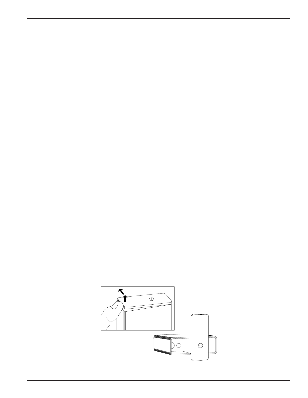
To replace the battery, open the bottom battery door cover with your thumb, rotate the door until it is perpendicular
with the case and allow the battery to fall out of the compartment into your hand. It is difficult to install the battery
backwards. Observe the large and small holes in the battery contact pad before inserting a new battery. Insert the
contact end of the battery first, making sure the contacts are aligned with the holes in the contact pad, and then
swing the door closed. You will feel it snap into place when it is fully closed.
1
“alkaline” or “lithium.” Short
To open the battery
compartment door, push the
door up and away from the case
with your thumb, then swing
open.
Figure 4 - Battery Replacement
Rio Rancho, NM – USA
2
7
Page 8

TROUBLESHOOTING
SYMPTOM POSSIBLE CAUSE
LED NOT LIT • Battery not installed or depleted
• Power switch not on.
NO SOUND IN HEADPHONE • AUDIO LEVEL turned all the way down.
• Headphone plug not inserted fully.
• Defective headphone
• Transmitter not operating. (See separate transmitter manual.)
• Mono Plug /Stereo Plug switch set to wrong position
DISTORTED SOUND
lamps
HISS AND NOISE,
AUDIBLE DROPOUTS
SHORT RANGE • Receiver earphone cable is also the antenna. Make sure the cable
• Transmitter gain (audio level) is far too high. Check mod level
on transmitter as it is being used. (Refer to Operating
Instructions section in the transmitter manual for details on gain
adjustment.)
• MAX LEVEL control may be set too low. See the GENERAL
TECHNICAL DESCRIPTION section for proper adjustment.
• Receiver output may be mismatched with the headset or
earphone. Adjust Audio Level on receiver to the correct level
for the headset or earphone.
• Excessive wind noise or breath “pops.” Reposition microphone
and/or use a larger windscreen.
• Receiver may be tuned to an intermod. Reprogram the receiver.
• Mono Plug/Stereo Plug switch set to wrong position.
• Transmitter gain (audio level) far too low.
• Receiver antenna missing or obstructed. (Headphone cable is
the antenna.)
• Transmitter antenna missing or obstructed.
• Operating range too great.
is not coiled or wound up or wrapped around the receiver case.
• Improper transmitter antenna.
8
Page 9

IFB Receiver
SPECIFICATIONS AND FEATURES
Operating frequencies: 537.6 MHz to 862.0 MHz
Number of frequencies: 256 per block (using 26 MHz maximum wide band)
Channel spacing: 100 kHz (25 kHz programmable)
Frequency control: Crystal Controlled Phase Locked Loop
Sensitivity: 1 uv (20 dB SINAD)
Signal/Noise ratio: 95 dB A-weighted
Squelch quieting: 90 dB
AM rejection: 50 dB, 10 uv to 100 mv
Modulation acceptance: ±20 kHz
Spurious rejection: Greater than 70 dB
Third order intercept: 0 dBm
Frequency response: 100 Hz to 10 kHz, (±1db)
Pilot tone: 29.997 kHz, 4.5 kHz deviation (fixed crystal controlled)
Audio output, headphone: 1 Vrms into 50 ohms minimum
Antenna: Headphone cable
Programmable memory: 5 frequencies
Front panel controls: Single knob controls Audio Output Level, Power on, programming
Indicators: 1 red LED Indicator for power on, blinks to indicate channel number, blinks
Power requirement: Single 9V Alkaline Battery for approximately 8 hours operation.
Power consumption: 60 ma.
Weight: 7.3 oz with battery
Size: 3.6 x 2.4 x 0.8 inches (housing only, belt clip and
and Scan Frequency Selection
fast during scan, and has short/long blinking for low batter y.
knob extend beyond the housing.)
Specifications subject to change without notice.
CE Compliance: ETS 300 445
Lectrosonics Model: IFB R5 FM Receiver
This product meets the CE Compliance Standards - ETS 300 445; January
1996. A copy of the Declaration of Conformity may be requested from your
dealer or by contacting the factory directly:
Lectrosonics, Inc.
Marketing Department
581 Laser Rd. NE, Rio Rancho, NM 87124 USA
tel: 505-892-4501 fax: 505-892-6243 e-mail:
marketing@lectrosonics.com
Rio Rancho, NM – USA
9
Page 10

LIMITED ONE YEAR WARRANTY
LIMITED ONE YEAR WARRANTY
The equipment is warranted for one year from date of purchase against defects in
materials or workmanship provided it was purchased from an authorized dealer. This
warranty does not cover equipment which has been abused or damaged by careless
handling or shipping. This warranty does not apply to used or demonstrator equipment.
Should any defect develop, Lectrosonics, Inc. will, at our option, repair or replace any
defective parts without charge for either parts or labor. If Lectrosonics, Inc. cannot
correct the defect in your equipment, it will be replaced at no charge with a similar new
item. Lectrosonics, Inc. will pay for the cost of returning your equipment to you.
This warranty applies only to items returned to Lectrosonics, Inc. or an authorized
dealer, shipping costs prepaid, within one year from the date of purchase.
This Limited Warranty is governed by the laws of the State of New Mexico. It states the
entire liablility of Lectrosonics Inc. and the entire remedy of the purchaser for any
breach of warranty as outlined above. NEITHER LECTROSONICS, INC. NOR
ANYONE INVOLVED IN THE PRODUCTION OR DELIVERY OF THE EQUIPMENT
SHALL BE LIABLE FOR ANY INDIRECT, SPECIAL, PUNITIVE, CONSEQUENTIAL,
OR INCIDENTAL DAMAGES ARISING OUT OF THE USE OR INABILITY TO USE
THIS EQUIPMENT EVEN IF LECTROSONICS, INC. HAS BEEN ADVISED OF THE
POSSIBILITY OF SUCH DAMAGES. IN NO EVENT SHALL THE LIABILITY OF
LECTROSONICS, INC. EXCEED THE PURCHASE PRICE OF ANY DEFECTIVE
EQUIPMENT.
This warranty gives you specific legal rights. You may have additional legal rights which
vary from state to state.
SERVICE AND REPAIR
If your system malfunctions, you should attempt to correct or isolate the trouble before concluding that the equipment
needs repair. Make sure you have followed the setup procedure and operating instructions. Check out the interconnecting cords and then go through the TROUBLESHOOTING section in the manual
We strongly recommend that you do not try to repair the equipment yourself and do not have the local repair shop
attempt anything other than the simplest repair. If the repair is more complicated than a broken wire or loose connection, send the unit to the factory for repair and service. Don’t attempt to adjust any controls inside the units.
Once set at the factory, the various controls and trimmers do not drift with age or vibration and never require readjustment. There are no adjustments inside that will make a malfunctioning unit start working.
LECTROSONICS, INC.
581 LASER ROAD
RIO RANCHO, NM 87124 USA
July 12, 2001
 Loading...