

Page 1

R185
VHF RECEIVER
OPERATING INSTRUCTIONS
and trouble-shooting guide
LECTROSONICS, INC.
Rio Rancho, NM
Page 2

2
Page 3

INTRODUCTION
Thank you for selecting the Lectrosonics system. The R185 represents over 80 combined years of experience in
the design of RF and audio devices, and sets new standards for RF performance and flexibility.
The R185 receiver was designed for professional users who demand outstanding performance and flexibility. It is a
single antenna, single channel design compatible with all Lectrosonics VHF 185 Series transmitters. The R185 may
be operated from 110V AC or from 12V DC, providing a high degree of versatility.
The R185 also functions as a receiver "module" for multi-channel receiver systems using 19 inch rack mounted
assemblies. Over 24 compatible frequencies are available allowing reliable, large-scale wireless stage productions
to run with no problems caused by cross-talk or intermodulation. RF/power distribution modules and 19" rack
mount assemblies are available to combine R185 receivers and simplify multi-channel installations.
Sharp filtering with minimal amplification in the front-end, narrow-band crystal filtering in the first IF stage, and a
double-balanced diode mixer all work together to provide extremely high selectivity, superb IM rejection, and very
high sensitivity. The end result of this design offers benefits for both the single channel and multi-channel user by
providing exceptional operating range and protection from interference.
TABLE OF CONTENTS
INTRODUCTION .......................................... 2
GENERAL TECHNICAL DESCRIPTION .......................... 3
RECEIVER FRONT PANEL ................................... 4
RECEIVER REAR PANEL .................................... 5
ANTENNA USE AND PLACEMENT ............................. 6
OPERATING INSTRUCTIONS ................................. 7
INDICATOR QUICK REFERENCE .............................. 7
TROUBLESHOOTING ....................................... 8
R185 REPLACEMENT PARTS and ACCESSORIES ................. 8
SERVICE AND REPAIR ..................................... 9
RETURNING UNITS FOR REPAIR ............................. 9
R185 SPECIFICATIONS AND FEATURES ........................ 10
WARRANTY ........................................ Back cover
3
Page 4
GENERAL TECHNICAL DESCRIPTION
6 SECTION
ACTIVE FILTERS SEPARATE
ANT
LC
FILTERS
IF AMP
2:1
SQUELCH
NOISE
AUDIO
0.5uV
HELICAL
RESONATOR
DBL BAL
DIODE
MIXER
6 POLE
HIGH FREQ
CRYSTAL
FILTER
FIRST
OSCILLATOR
DBL BAL
ACTIVE MIXER
SECOND
OSCILLATOR
DBL TUNED
DISCRIMINATOR
NOISE AND AUDIO
COMPLEMENTARY
EXPANDER
BALANCED
OUTPUT STAGE
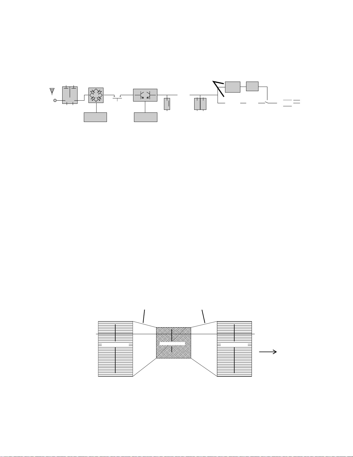
The R185 receiver is comprised of five functional subsystems: the RF front-end, the double balanced mixer/local
oscillator, the first IF filter, the second IF filter and demodulator, the compandor and audio output section.
Figure 1 - R185 Block Diagram
The RF front-end consists of three cascaded pairs of helical resonators for high selectivity. Between the first and
second pair, and the second and third pair of helical resonators are low noise, grounded gate J-FET amplifiers.
These amplifiers are designed to provide only enough gain to make up for the loss through the helical resonators.
This combination of low front-end gain, coupled with the extremely high selectivity of the helical resonators prevents
overload in the mixer and provides exceptionally high image rejection, even with extremely strong RF signals.
Rejection of out-of-band signals is maximized, and intermodulation products are suppressed.
The first mixer stage consists of a high level, double balanced diode mixer. The oscillator is biased from a
regulated supply, yielding stable performance. The local oscillator crystal operates at approximately 16 MHz, and
can be adjusted above and below the nominal frequency in order to place the 21.4 MHz IF in the center of the
crystal filter’s narrow passband. The high selectivity of the crystal filter stage further minimizes the possibility of
interference from signals on adjacent frequencies.
The second IF filter and the audio demodulator, as well as the squelch and RF LED drive are provided by one
monolithic integrated circuit. The second IF filter is centered on 1MHz, and drives a double tuned quadrature type
FM demodulator. The squelch circuit is a supersonic noise detector type and is factory set for a -20dB SINAD level
(about .5uV). The squelch level is regulated and temperature compensated to maintain a consistent squelch level
under all conditions.
The compandor is driven by a multiple pole active low-pass filter. This filter ensures that supersonic noise will not
cause the compandor to increase gain incorrectly. The compandor senses the signal level, and dynamically
increases the gain for loud signals or decreases the gain for soft signals. In this way, the original dynamic range of
the transmitted signal is restored, while preserving a high signal-to-noise ratio. The expansion ratio is 2:1, which
produces a 2dB change in output level for a 1dB change in input level. In addition, the compandor has a deemphasis network that is complementary to the pre-emphasis network in the transmitter.
2:1 1:2
COMPRESSION EXPANSION
+20dB
+10dB
0dB
AUDIO
SOURCE
-80dB
TRANSMITTER RECEIVER
RF LINK
100dB dynamic range
50dB dynamic range
100dB dynamic range
+20dB
+10dB
0dB
TO AUDIO
SYSTEM
-40dB-40dB
-80dB
Figure 2 - Compandor Action
4
Page 5

RECEIVER FRONT PANEL
MODULATION INDICATORS Nine (9) LEDs indicate the audio level (modulation) of the incoming signal, which are
typically used for proper adjustment of the transmitter’s "MIC LEVEL" or "GAIN." The left-most LED (red) functions
as a pilot lamp to indicate that the receiver is powered up. The seven green LEDs indicate the modulation level of
the signal. The right-most yellow LED indicates maximum modulation and that the transmitter audio input is
probably being driven into limiting.
OFF/MUTE/ON This switch turns the receiver power off and on and selects either an "audio mute" or "audio on"
operation. The "audio mute" position is normally used to cut the audio output from the receiver so that the
modulation LEDs may be observed while adjusting the transmitter gain.
RF INDICATOR This LED glows when the transmitter is turned on and the receiver has a useable RF signal.
When the carrier signal from the transmitter is too weak to produce a clean audio signal, the lamp will go out.
OUTPUT ATTENUATOR This control knob adjusts the output level of the two balanced outputs on the rear panel
(XLR and 1/4"). In a fully clock-wise position, the output at the XLR jack will be 100mV when the signal is at full
modulation. The "-3," "-12dB", "-20", and "-50" markings indicate the knob position that will lower the audio output
by that amount. In other words, with the OUTPUT ATTENUATOR knob in the "-12dB" position, the audio output
level at the XLR jack will be 12 dB below 100mV when the signal is at full modulation. These markings should not
be confused with absolute level references such as "-20 dBm", "-20 dBu", etc.
LECTROSONICS
-24 -12-20
dB AUDIO LEVEL
RF
-7 -3
AUDIO
MUTE
0 +3
-15
OFF ON
POWER
Figure 3 - R185 Front Panel
-12dB
-20
0dB
-50
OUTPUT
ATTENUATOR
N
O
R
-3
M
A
L
5
Page 6

RECEIVER REAR PANEL
ANTENNA INPUT This input connects to any 50 Ohm antenna with a BNC type connector.
12 VDC INPUT This input connects to the supplied CH-12 AC adapter for powering the receiver from a 110/120V
AC source. The receiver may also be powered from external 12 Volt DC sources using the correct plug
(Switchcraft S-760 power plug). The center pin is positive. (+). If the external DC source is of the wrong polarity,
the R185 receiver will not operate. The unit is equipped with a "reverse polarity diode" at the DC power input which
prevents damage in the case of improper polarity. If a DC source of the wrong polarity is connected to the R185,
the diode will shunt the DC to ground through the internal polyfuse. Correct the polarity and wait approximately 15
seconds for the polyfuse to recover then re-connect the external DC power.
AUDIO OUTPUTS
XLR
: This connector supplies a balanced, low impedance output at microphone level. The audio
signal is present on pins 2 and 3, while pin 1 is ground. The output level of this jack is controlled by
the OUTPUT ATTENUATOR control on the front panel of the receiver. Pin 2 is "hot" in terms of
signal phase.
1/4": A high level (700mV max.) output at medium impedance (600 Ohms). This is a three
conductor jack with the tip and ring carrying the signal and the sleeve as shield. The tip is "hot" in
terms of signal phase. Output from this jack is controlled by the OUTPUT ATTENUATOR control on
the front panel.
RCA: A 1 Volt "line" output at 1K Ohms. The output of this jack is not controlled by the OUTPUT
ATTENUATOR control on the front panel.
AUDIO IN This is an audio input providing a unity gain mixing bus input via a standard RCA jack. Signal applied
to this jack will appear at all three output jacks. This input is provided as a convenience in multiple channel
installations with simple mixing requirements, or for patching in another audio source (tape deck, etc.). Multiple
R185 receivers may be "stacked" with mixed audio output by connecting the LINE OUT jack of one receiver to the
AUDIO IN of the next receiver, and so on. Up to four or five receivers may be "stacked" in this manner before
noise build-up becomes objectionable.
AUDIO OUTPUTS
BAL 600
700mV max
LINE OUT
21
BAL MIC LEVEL
100mV max
AUDIO IN
Figure 4 - R185 Rear Panel
3
LECTROSONICS, INC.
RIO RANCHO, NM MADE IN USA
6
ANTENNA
-
12V DC INPUT
+
Page 7

ANTENNA USE AND PLACEMENT
A wireless transmitter sends a radio signal out in all directions. Indoors, this signal will often bounce off nearby
walls, ceilings, etc. and a strong reflection can arrive at the receiver antenna along with the direct signal. Outdoors,
reflections can occur from nearby cars, trucks or metal buildings. If the direct and reflected signals are out of
phase with each other at the receiver antenna, a cancellation will occur. The result is a "drop-out." A drop-out
sounds like either audible noise (hiss), or in severe cases, may result in a complete loss of the carrier and the
sound. Moving the transmitter even a few inches will change the sound of the hum or hiss, or eliminate it. A dropout situation may be either better or worse as the crowd fills and/or leaves the room or the area, or when the
transmitter or receiver is operated in a different location.
The illustration below depicts a simplified multi-path dropout. This drawing is overly simplified to emphasize phase
cancellation at the receiver antenna. In actual use, there are numerous different paths that the radio signal can
take simultaneously, causing a multitude of different signals arriving at the receiver antenna. The resultant RF
signal level at the receiver antenna can be very low if there is significant phase cancellation. The high sensitivity of
the R185 minimizes dropouts in multi-path environments, since it will continue to operate with a usable audio signal
to noise ratio even with weak RF signal inputs.
In general, it is usually best to position the antenna so that it is not within 3 or 4 feet of large metal surfaces. If this
is not possible, try to position the antenna so that it is as far away from the metal surface as is practical. It is also
good to position the receiver so that there is a direct "line of sight" between the transmitter and the receiver
antenna. In situations where the operating range is less than about 50 feet, the antenna positioning is much less
critical.
Lectrosonics transmitters radiate power very efficiently, and the receivers are very sensitive. This reduces dropouts to an insignificant level. If, however, you do encounter drop-outs frequently, call the factory or consult your
dealer. There is probably a simple solution.
Figure 5 - Multi-Path Dropout
7
Page 8

OPERATING INSTRUCTIONS
1) Connect the power supply.
2) Attach the antenna.
3) Connect the audio cable from the sound system or recorder to the receiver.
4) Set the front panel switch to the "MUTE" position. Check to see that the red POWER LED lights up (the leftmost LED in the 9-LED display).
5) Adjust the transmitter "gain." THIS IS PERHAPS THE MOST IMPORTANT STEP IN THE SET UP
PROCEDURE. See your transmitter manual for specific directions on the proper gain adjustment of your particular
transmitter.
6) After adjusting the transmitter gain, move the OFF/MUTE/ON switch to the "ON" position.
7) Operate the system and adjust the receiver output level as required for your equipment. The input levels on
different recording and PA equipment vary, which may require that you set the OUTPUT ATTENUATOR control in
an intermediate position. Try different settings and listen to the results. If the output of the receiver is too high, you
may hear distortion or a loss of the natural dynamics of the audio signal. If the output is too low, you may hear
steady noise (hiss) along with the audio.
NOTE: The OUTPUT ATTENUATOR knob does not adjust the 9 LED indicator.
INDICATOR QUICK REFERENCE
RF LEDs - The RF LED lights when the transmitter is turned on and the receiver is picking up a strong enough
carrier to provide a good audio signal.
POWER - The left-most LED (red) in the 9-LED display lights up when the receiver is properly connected to a
power supply and switched on.
MODULATION - The audio level is indicated by 9 LEDs on the front panel. The normal operating level occurs
when the intermediate (green) LEDs are lighting up with the audio. The right-most LED (yellow) lights up when the
audio level is high and the signal is being limited in the transmitter. An extremely high audio level may cause
distortion. If none of the green LEDs light up when audio is being produced through the system, the audio level is
too low, which may produce audible background noise (hiss) in the audio. The audio level is adjusted with the
transmitter GAIN or MIC LEVEL control.
8
Page 9

TROUBLESHOOTING
Before going through the following chart, be sure that you have a good battery in the transmitter. It is important
that you follow these steps in the sequence listed.
SYMPTOM POSSIBLE CAUSE
RECEIVER RF LAMP OFF 1) Transmitter not turned on.
2) Transmitter battery is dead.
3) Receiver antenna missing or improperly positioned.
4) Transmitter and receiver not on same frequency. Check
labels on transmitter and receiver.
5) Operating range is too great.
NO SOUND AND RECEIVER MOD LEVEL LEDs ARE OFF
1) Transmitter audio muted. See transmitter manual for
proper settings.
NO SOUND BUT RECEIVER MOD LEVEL LEDs ARE ON
1) Receiver audio is muted. Switch receiver to ON.
2) Receiver audio output is disconnected or cable is
defective or mis-wired.
3) Sound system or recorder input is turned down.
DISTORTED SOUND 1) Transmitter gain (audio level) is too high. Speak or sing
into the transmitter and check mod level lamps on
transmitter and receiver.
2) Receiver output may be mis-matched with the sound
system or recorder input.
3) Excessive wind noise or breath "pops."
HISS AND NOISE -- AUDIBLE DROPOUTS 1) Transmitter gain (audio level) too low.
2) Receiver antenna missing or obstructed.
3) Operating range too great.
EXCESSIVE FEEDBACK 1) Transmitter gain (audio level) too high. Check gain
adjustment and/or reduce receiver output level.
2) Transmitter too close to speaker system.
3) Move transmitter closer to the user’s mouth.
R185 REPLACEMENT PARTS and ACCESSORIES
Part No. Description
CH-12 110 Volt AC adapter for R185 receiver.
A-185 Coax Remote, folded-dipole antenna with coaxial cable.
A-185-BNC Telescoping 1/4 wave whip on a swiveling BNC connector.
A-200 Remote dipole antenna with aluminum mounting block;
supplied with one built-in telescoping whip and one
detachable telescoping whip.
RMP-3 19" rack mounting kit for one to three R185 receivers. Each
receiver requires a separate antenna and power supply.
9
Page 10

SERVICE AND REPAIR
If your system malfunctions, you should attempt to correct or isolate the trouble before concluding that the
equipment needs repair. Make sure you have followed the setup procedure and operating instructions. Check out
the inter-connecting cords and then go through the TROUBLE SHOOTING section in the manual
We strongly recommend that you do not try to repair the equipment yourself and do not have the local repair shop
attempt anything other than the simplest repair. If the repair is more complicated than a broken wire or loose
connection, send the unit to the factory for repair and service. Don’t attempt to adjust any controls inside the units.
Once set at the factory, the various controls and trimmers do not drift with age or vibration and never require
readjustment. There are no adjustments inside that will make a malfunctioning unit start working.
LECTROSONICS service department is equipped and staffed to quickly repair your equipment. In-warranty repairs
are made at no charge in accordance with the terms of the warranty. Out of warranty repairs are charged at a
modest flat rate plus parts and shipping. Since it takes almost as much time and effort to determine what is wrong
as it does to make the repair, there is a charge for an exact quotation. We will be happy to quote approximate
charges by phone for out of warranty repairs.
RETURNING UNITS FOR REPAIR
You will save yourself time and trouble if you will follow the steps below:
A. DO NOT return equipment to the factory for repair without first contacting us by letter or by phone. We need to
know the nature of the problem, the model number and the serial number of the equipment. We also need a
phone number where you can be reached 8 am to 4 pm (Mountain Standard Time).
B. After receiving your request, we will issue you a return authorization number (R.A.). This number will help
speed your repair through our receiving and repair departments. The return authorization number must be
clearly shown on the outside of the shipping container.
C. Pack the equipment carefully and ship to us, shipping costs prepaid. If necessary, we can provide you with the
proper packing materials. UPS is usually the best way to ship the units. Heavy units should be "double-boxed"
for safe transport.
D. We also strongly recommend that you insure the equipment, since we cannot be responsible for loss of or
damage to equipment that you ship. Of course, we insure the equipment when we ship it back to you.
Mailing address: Shipping address:
Lectrosonics, Inc. Lectrosonics, Inc.
PO Box 15900 581 Laser Rd.
Rio Rancho, NM 87174 Rio Rancho, NM 87124
USA USA
Telephones:
Regular: (505) 892-4501
WATS: (800) 821-1121
FAX: (505) 892-6243
10
Page 11

R185 SPECIFICATIONS AND FEATURES
Operating frequencies: 150 to 216 MHz, crystal controlled
Sensitivity: Better than 0.5uV for 20 dB quieting without compandor;
1.7uV for 50dB S/N ratio with compandor
Signal/noise ratio: 96 dB (A-weighted), typical overall system
Squelch quieting: Greater than 110 dB
AM rejection: -60 dB (10uV to 0.1 Volts)
Modulation acceptance: ± 15 kHz
Image and spurious rejection: Greater than 100 dB
Third order intercept: +5 dBm
Audio outputs: * XLR: 200 Ohm bal.; 100mV max.
* 1/4 inch: 600 Ohm bal.; 700mV max.
* RCA: 1K Ohms unbalanced; 1 Volt max.
Audio input: Unity gain RCA jack for audio mixing bus
Antenna input: BNC female; 50 Ohm impedance
Controls: * Front panel attenuator controls balanced outputs
* 3 position power/function switch
Indicators: * Red LED for power "ON"
* 8 LEDs for modulation level
* "RF" LED for transmitter "ON" (carrier/squelch indication)
Power requirements: * 12 Volt DC (rear panel jack)
* 110 Volt AC (using supplied CH-12 AC adapter)
Power consumption: 90 mA
Weight: 2.65 lbs.
Dimensions: 2.9 x 5.3 x 7.4 inches
11
Page 12

LIMITED ONE YEAR WARRANTY
The equipment is warranted for one year from date of purchase against defects
in materials or workmanship provided it was purchased from an authorized
dealer. This warranty does not cover equipment which has been abused or
damaged by careless handling or shipping. This warranty does not apply to
used or demonstrator equipment.
Should any defect develop, we will, at our option, repair or replace any
defective parts without charge for either parts or labor. If we cannot correct the
defect in your equipment, we will replace it at no charge with a similar new item.
We will pay for the cost of returning your merchandise to you.
This warranty applies only to items returned to us, shipping costs prepaid, within
one year from the date of purchase.
This warranty gives you specific legal rights. You may have additional legal
rights which vary from state to state.
LECTROSONICS, INC.
581 LASER ROAD
RIO RANCHO, NM 87124 USA August 17, 1996
 Loading...