

Page 1

INSTRUCTION MANUAL
R172 DUAL-RECEIVER
LECTROSONICS, INC.
581 Laser Road
Rio Rancho, NM 87124 USA
Tel (800) 821-1121 or (505) 892-4501
fax (505) 892-6243
e-mail: sales@lectrosonics.com
web: www.lectrosonics.com
Page 2

INTRODUCTION
The R172 receiver is a fixed frequency design two channel wireless microphone receiver. Designed to offer two
simultaneous channels of wireless microphones, the R172 will can operate both channels from one antenna or two
for passive diversity operation. The dual antenna configuration reduces the probability of dropouts resulting from
multipath interference. Additionally, the audio output from this receiver can be either split into discrete channels or
mixed internally for maximum flexibility in any audio installation.
The RF signal first passes through RF filter coils coupled with ultra-low noise J-FETs. The J-FETs are used to
provide enough gain to compensate for inherent losses in the filter stages. Crystal controlled oscillators are used to
minimize drift and are stable over a wide range of temperatures. The output of the front end is then fed to a double
balanced diode mixer which generates an interference free IF signal. The mixer is followed by an LC filter stage and
the signal is amplified.
TABLE OF CONTENTS
Receiver Front Panel ............................................................................2
Receiver Rear Panel .............................................................................3
Operating Instructions: .........................................................................4
Set up sequence
Antenna Use and Placement.................................................................6
Multi-channel Audio Mixing ...................................................................7
Troubleshooting Guide..........................................................................8
Specifications .......................................................................................9
Factory Repair Service .........................................................................10
Page 3
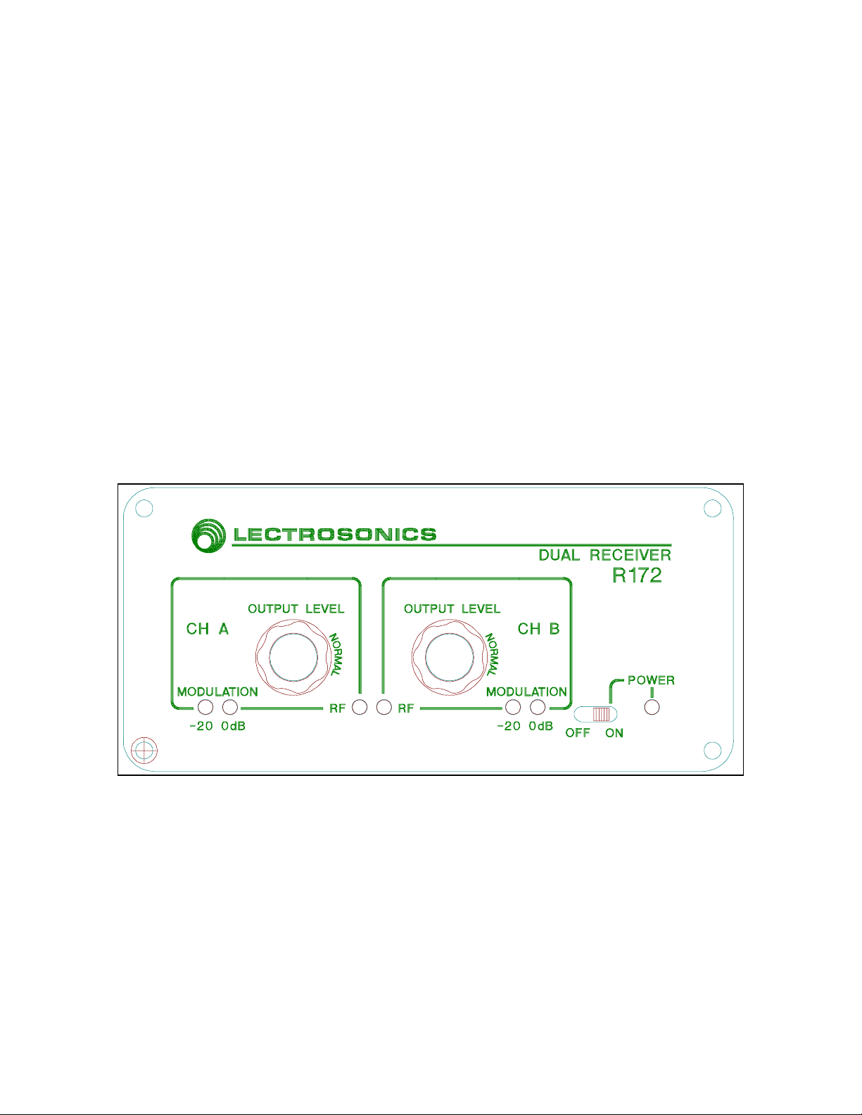
Front panel controls on the R172 are identical for each channel and operate independently from each other.
-- Indicates the modulation (audio level) of the incoming signal. The green LED indicates an
MODULATION
adequate modulation level. The red LED indicates maximum or "peak" modulation.
OUTPUT LEVEL
output levels of the XLR jacks in the rear by rotating the knob counter-clockwise.
LED -- Light when the transmitters are turned on. If the carrier signal is too weak to produce a quality signal,
RF
the lamp will go out. Each channel has it's own independent RF LED.
POWER
OFF ON SWITCH -
-- An output attenuator is used to reduce the audio output level of the receiver. Reduces the audio
NOTE: This control does not affect the
it also does not affect the output level of the "
LED -- Lights when the receiver is turned on.
This switch activates the receiver when set to the "ON" position.
RECEIVER FRONT PANEL
MODULATION
LINE LEVEL
display, the RF LED or the
" RCA jack.
LED --
POWER
Figure 1 R172 Front Panel
Page 4

control.
SNGL.
will mix the signals
MIXED
ANTENNA
shipped with a telescoping whip antenna and a coaxial antenna. Rack mounted units are shipped with two coaxial
antennas.
ANTENNA MODE -
antennas are used set the switch to
12 VDC DC POWER
powering the unit from a 110 V AC outlet -- the receiver may also be powered from 12 volt DC sources using the
correct plug (Switchcraft S-760 power plug); the center pin is positive (+).
MIC LEVEL
inputs
LINE LEVEL
level of this RCA jack is not affected by the front panel
SEPARATE MIXED SWITCH SEPARATE
internally, allowing both channels to be output through either output jack.
AUX INPUTS
output. Also allows "stacking" multiple receivers.
terminals -- Standard BNC 50 ohm connectors for connecting the antennas. The R172 is normally
The unit may be operated as either a single antenna or a dual antenna system. If two
-- Connect the power supply here -- the CH-12 AC adapter is supplied with the receiver for
-- 3 pin XLR at microphone level (80mV max.); 200 ohm impedance for either balanced or unbalanced
-- RCA phono jack at "line" level (1 volt max); 1K ohm impedance for unbalanced inputs. The output
will keep the signals from the two channels discrete. Setting the switch to
-- RCA phono jack inputs accept external tape deck or other audio source; mixes audio with receiver
RECEIVER REAR PANEL
. If operating with only one antenna, set the switch to
DUAL
AUDIO OUTPUTS
OUTPUT LEVEL
Allows the "A" and "B" audio signals to be mixed, if desired. Setting the switch to
AUDIO INPUT
(mixing bus)
Page 5

Figure 2 R172 Rear Panel
Page 6

OPERATING INSTRUCTIONS
SET UP AND OPERATION SEQUENCE
1) CONNECT POWER CORD
labeled "12 VDC INPUT." Insert the plug fully into the jack.
2) ATTACH THE ANTENNAS
the unit will have a telescoping whip antenna and a coaxial dipole antenna (this antenna looks like a piece of cable
with a small loop in one end and a BNC connector on the other). If it has been mounted into an RMP3 rack kit, then
it will have two coaxial dipole antennas.
If the system will be installed with one antenna -
marked
If the antenna is the telescoping whip, extend the antenna to its full length.
The coaxial dipole antenna should be uncoiled and led away from the receiver. The loop on the end is
provided as a convenient attachment point. The cable should be hung on a wall or suspended so the last
3.5 ft are straight and not close to any metal surfaces such as file cabinets, metals walls, or metal studs.
Wood stud drywall construction will present no problems and the antenna may be hung against the wall.
Some contractors have actually run the antenna up inside hollow walls. Be sure to test the system before
committing the system to a particular antenna placement.
on the rear of the receiver. Set the
SNGL
-- Plug the connector of the CH-12 adapter included with the receiver into the jack
- Two antennas are provided with the receiver. If the system is not rack mounted,
Attach the single antenna to the BNC connector
ANTENNA MODE
switch to
SNGL
Figure 3 Single Antenna Options
Page 7

If the system will be installed with dual antennas -
on the back of the receiver. Set the
is used, fully extend the whip.
AT THE RECEIVER.
There is little to no benefit of placing the antennas side by side. Place the coaxial
ANTENNA MODE
DO NOT USE TWO TELESCOPING WHIPS ATTACHED SIDE BY SIDE
Attach both antennas to the dual BNC connectors
switch to the
position. If a telescoping whip
DUAL
antennas in the same manner as described above. The two antennas should be placed at least 6 ft apart
for best reception. This will put each antenna into a different signal path (diversity) and reduce the
possibility of dropout.
Figure 4 Dual Antenna Options
Page 8

3) CONNECT THE AUDIO CABLE/S
If the receiver will be connected directly to an amplifier and there is only one audio input available, set the
SEPARATE/MIXED
switch to the mixed position and connect the cable to either the "A" or "B" output jack.
You may also used the MIXED position to connect the receiver to a tape deck and an amplifier for
simultaneous recording. See the illustration below.
If the receiver will be connected to a mixer or an amplifier with two (or more) audio inputs, then set the
switch to
SEPARATE
. By doing so, the audio signals will be separate and can be adjusted independently
at the mixer or amplifier. Connect the receiver with two cables to the amplifier or mixer.
Figure 5 Audio Connections
-
4) SET FRONT PANEL SWITCH TO "ON" POSITION
5) ADJUST TRANSMITTER "MIC LEVEL"
This is perhaps the most important step in the set up procedure. See your transmitter manual for specific
(See transmitter manual)
instructions on the proper gain adjustment of your transmitter. With some transmitter models you will
need to observe the
transmitter.
MODULATION
LED's on the receiver front panel as you adjust the gain on the
6) SET THE OUTPUT LEVELS
"
NORMAL
- Set the front panel controls for
" (at the 3 o'clock position)
7) ADJUST THE SOUND SYSTEM VOLUME
- Be sure the POWER LED lights.
OUTPUT LEVEL
on each channel to the
Page 9

Extend the antennas fully. Position the antennas so that they are not touching each other or within 3 or 4 feet of
large metal surfaces. It is also good practice to position the receiver so that there is a direct "line of sight" between
the transmitter and the receiver antenna. In the dual antenna mode, place the antennas at least 6 ft apart. If the
installation has two rooms serviced by the same receiver, you may want to extend one antenna into one room and
place the other antenna into the second room. See the illustration below.
A wireless transmitter sends a radio signal out in all directions. This signal will often bounce off nearby walls,
ceilings, etc. and a strong reflection can arrive at the receiver antenna along with the direct signal. If the direct and
reflected signals are out of phase with each other a cancellation may occur. The result would be a "drop out." A
drop out sounds like either audible noise (hiss), or in severe cases, may result in a complete loss of the sound when
the transmitter is positioned in certain locations in the room. A dropout normally sounds like "hum" or "hiss."
Moving the transmitter (even a few inches) will change the hum or hiss, or eliminate it. A dropout situation may be
either better or worse as the crowd fills and/or leaves the room. The dual antenna configuration (passive diversity)
of the R172 helps reduce the probability of this problem occurring.
In the event that you do encounter a dropout problem, first try moving the receiver/antennas at least 3 or 4 feet from
where they were. This may alleviate the dropout problem. If dropouts are still a problem, try moving the receiver
and/or the antennas to an entirely different location in the room.
effect if there is a telescoping whip antenna attached directly to the receiver.
cable type, you will only need to move them around.
ANTENNA USE AND PLACEMENT
Note - moving the receiver will only have an
If both antennas are the coaxial
Page 10

The R172 receiver offers a unique feature that eliminates the necessity of using an external audio mixer in
multi-channel applications. When using two R172 receivers together, the
provide "unity gain" mixing of the audio signals. This means that the audio output of the receivers may be mixed
together through these connectors without affecting the volume levels. Connect the
receiver to the AUDIO IN jack of the next receiver, then connect its
the next receiver, forming a "chain" as shown in the illustration.
Two receivers may be interconnected in this manner so that a single audio output is available from the output of the
last receiver in the "chain".
The output level of the
LEVEL
order to control the receiver outputs independently, you will need to use an external microphone mixer without the
"jumper" cords shown below.
A tape player (or other audio source) may be connected to the AUDIO IN jack on the rear panel to mix the tape
player output with the receiver output. Adjust the volume of the tape player with the volume control on the tape
player since there is not a separate control for this purpose on the receiver. You may also record from the R172 by
connecting to the
control on the last receiver in the "chain" will control the combined volume of all the receiver outputs. In
MIXING AN EXTERNAL TAPE DECK WITH RECEIVER OUTPUT
LINE LEVEL
LINE LEVEL
MULTI-CHANNEL AUDIO MIXING
LINE LEVEL
LINE LEVEL
RCA jack is not affected by the
jacks on the rear panel.
OUTPUT LEVEL
and
LINE LEVEL
jack to the
control. The
AUX INPUTS
jack of one
AUX INPUTS
OUTPUT
jacks
jack of
Page 11

TROUBLESHOOTING
Before going through the following chart, be sure that you have a good battery in the transmitter. It is
important that you follow these steps in the sequence listed.
SYMPTOM POSSIBLE CAUSE
TRANSMITTER BATTERY LED OFF
----------------------------------------------------------------
NO TRANSMITTER MOD LEVEL LEDs
----------------------------------------------------------------
RECEIVER RF LAMP OFF
----------------------------------------------------------------
NO SOUND AND RECEIVER MOD LEVEL LEDs ARE OFF
----------------------------------------------------------------
NO SOUND BUT RECEIVER MOD LEVEL LEDs ARE ON
----------------------------------------------------------------
DISTORTED SOUND
----------------------------------------------------------------
HISS AND NOISE -- AUDIBLE DROPOUTS
----------------------------------------------------------------
EXCESSIVE FEEDBACK
1) External LED is turned off. Check internal slide
switch.
2) Battery is inserted backwards.
3) Battery is dead.
1) Gain control turned all the way down.
2) Battery is in backwards. Check power LED.
3) Mic capsule is damaged or malfunctioning.
1) Transmitter not turned on.
2) Transmitter battery is dead.
3) Receiver antenna missing or improperly
positioned.
4) Transmitter and receiver not on same frequency.
Check labels on transmitter and receiver.
5) Operating range is too great.
Transmitter audio muted. Make sure bottom
panel "A" switch is turned on. Push switch
toward the letter "A" to turn the audio on.
1) Receiver audio is muted. Refer to receiver
manual.
2) Receiver audio output is disconnected or cable is
defective or mis-wired.
3) Sound system or recorder input is turned down.
1) Transmitter gain (audio level) is too high. Speak
or sing into the transmitter and check mod level
lamps on transmitter and receiver.
2) Receiver output may be mis-matched with the
sound system or recorder input.
3) Excessive wind noise or breath "pops."
1) Transmitter gain (audio level) too low.
2) Receiver antenna missing or obstructed.
3) Operating range too great.
1) Transmitter gain (audio level) too high. Check
gain adjustment and/or reduce receiver output
level.
2) Transmitter too close to speaker system.
3) Move transmitter closer to the user's mouth.
Page 12

Operating frequencies:
Sensitivity:
Signal/noise ratio:
Squelch quieting:
AM rejection:
Modulation acceptance:
Image/spurious rejection:
Audio outputs:
Audio input:
Antenna input:
Controls: OUTPUT LEVEL
Indicators: POWER
Power requirements:
Power consumption:
Weight:
Dimensions:
SPECIFICATIONS
150 to 216 MHz crystal controlled
1.0uV for 20dB SINAD
2.0uV for 50dB S/N ratio
96 dB A-weighted
greater than 96 dB
better than -40 dB
(10uV to 0.1 volts)
+/- 15KHz
greater than 100 dB
* XLR: 200 ohm balanced; 100mV max.
* RCA: 1K ohm unbalanced; 1 volt max.
RCA jack for unity gain audio mixing bus
BNC connectors; 50 ohm impedance
balanced outputs;
POWER
SEPARATE/MIXED
SNGL/DUAL ANTENNA MODE
MODULATION
modulation level on each channel
"RF" LED
* 12 volt DC direct to panel mounted jack
* 110 volt AC via CH-12 AC adapter
125 mA max.
2 lbs 5 oz.
2.9H x 5.3W x 7.4D inches
attenuators control A & B
switch
audio switch
LED for power "ON"
LEDs for
switch
Page 13

ALWAYS CONTACT THE FACTORY BEFORE SHIPPING ANYTHING BACK FOR SERVICE.
DO NOT try to repair this transmitter yourself.
DO NOT try to adjust any controls inside the unit. Alignment of the receivers requires a spectrum analyzer, an RF
voltmeter, and a wide bandwidth oscilloscope. The various controls and trimmers do not drift with age or vibration.
Once they are set at the factory they never require readjustment. There are no adjustments inside the unit that will
make a malfunctioning unit start working.
LECTROSONICS will supply, on request, a technical service package of schematics and alignment instructions to
qualified personnel. This information will be supplied free of charge.
LECTROSONICS service department is equipped and staffed to repair your equipment quickly. In-warranty repairs
are made at no charge in accordance with the terms of the warranty in the front of this manual. Out of warranty
repairs are charged at a modest flat rate plus parts. Since it takes almost as much time and effort to determine
what is wrong as it does to make the repair, there is a charge for an exact quotation. We will be happy to quote
approximate charges by phone.
FACTORY REPAIR SERVICE
RETURNING UNITS FOR REPAIR
Please save yourself time and trouble by following the steps outlined below:
1) Call or write first -- we will need to know the model number, serial number, and the nature of the
problem.
2) We will issue a return authorization number (RA) to you -- this number must be marked on the outside
of the carton.
3) Pack the equipment carefully -- if you need shipping containers, they are available from the factory.
4) We strongly recommend that you insure the equipment. We cannot be responsible for shipping
damage or loss. We insure it when it is shipped back to you.
Mailing address:
Lectrosonics, Inc.
PO Box 15900
Rio Rancho, NM 87124 USA
Shipping address:
Lectrosonics, Inc.
581 Laser Road
Rio Rancho, NM 87174 USA
Telephones: Regular: (505) 892-4501
Toll-free (outside NM): (800) 821-1121
FAX: (505) 892-6243
 Loading...