

Page 1

QUADUHFD
MULTI-CHANNEL WIRELESS SYSTEM
WITH RF/POWER DISTRIBUTION
OPERATING INSTRUCTIONS
and trouble-shooting guide
LECTROSONICS, INC.
Rio Rancho, NM USA
www.lectrosonics.com
Page 2

INTRODUCTION
The design of Lectrosonics Quad Pak systems has evolved over the years as a
result of suggestions garnered during many conversations with industry sound
mixers and production engineers. These suggestions, together with meticulous
attention to design and construction details, have resulted in a system that offers
portability, versatility, and “bullet-proof” reliability of operation.
The QUADUHFD system is a high performance, 4-channel wireless microphone
receiver system designed primarily for motion picture and television production in
the studio and in the field. The QUADUHFD is a dual-antenna, diversity design for
up to four UCR195, UCR195D, UCR200D, UCR205D or UCR210D diversity receivers. The European specification UCR300 receivers can also be installed.
Complete QUADUHFD systems consist of a rugged mechanical assembly with builtin rechargeable batteries for up to four receivers, one or two RF/power multi-couplers (depending upon the receivers installed) and various options for antennas and
chargers to meet a wide variety of applications. The mechanical assemblies are
covered with a padded, naugahyde carrying case with reinforced, zippered and
hinged front and rear panels for easy access to controls and connectors.
Problems such as interaction of receivers, intermodulation and desensitization have
been eliminated with the use of proven design principles in the active antenna multicouplers.
TABLE OF CONTENTS
INTRODUCTION ................................................................................................... 2
GENERAL TECHNICAL DESCRIPTION ............................................................. 3
FRONT PANEL DESCRIPTION............................................................................ 4
REAR PANEL DESCRIPTION .............................................................................. 5
INSTALLATION ...................................................................................................... 6
OPERATING INSTRUCTIONS ............................................................................. 6
TROUBLESHOOTING ........................................................................................... 7
SPECIFICATIONS ................................................................................................. 8
SERVICE AND REPAIR ........................................................................................ 9
RETURNING UNITS FOR REPAIR ...................................................................... 9
WARRANTY ........................................................................................... Back cover
2
Page 3
Multi-channel Wireless System
GENERAL TECHNICAL DESCRIPTION
The QUADUHFD consists of three sub-systems; the housing which contains the gel-cell power supply, the UDM6
RF/power distribution module and the UDM6S RF distribution module.
The housing is constructed of machined aluminum. A strap handle is bolted directly to the top panel of the housing
for ease of carrying. The lead-acid gel-cell batteries are connected in series to provide 12 VDC (nominal) power to
all the modules installed into the system. These batteries were selected for their recharge characteristics and
reliability under extreme conditions. The batteries are also highly resistant to damage caused by prolonged deep
discharge.
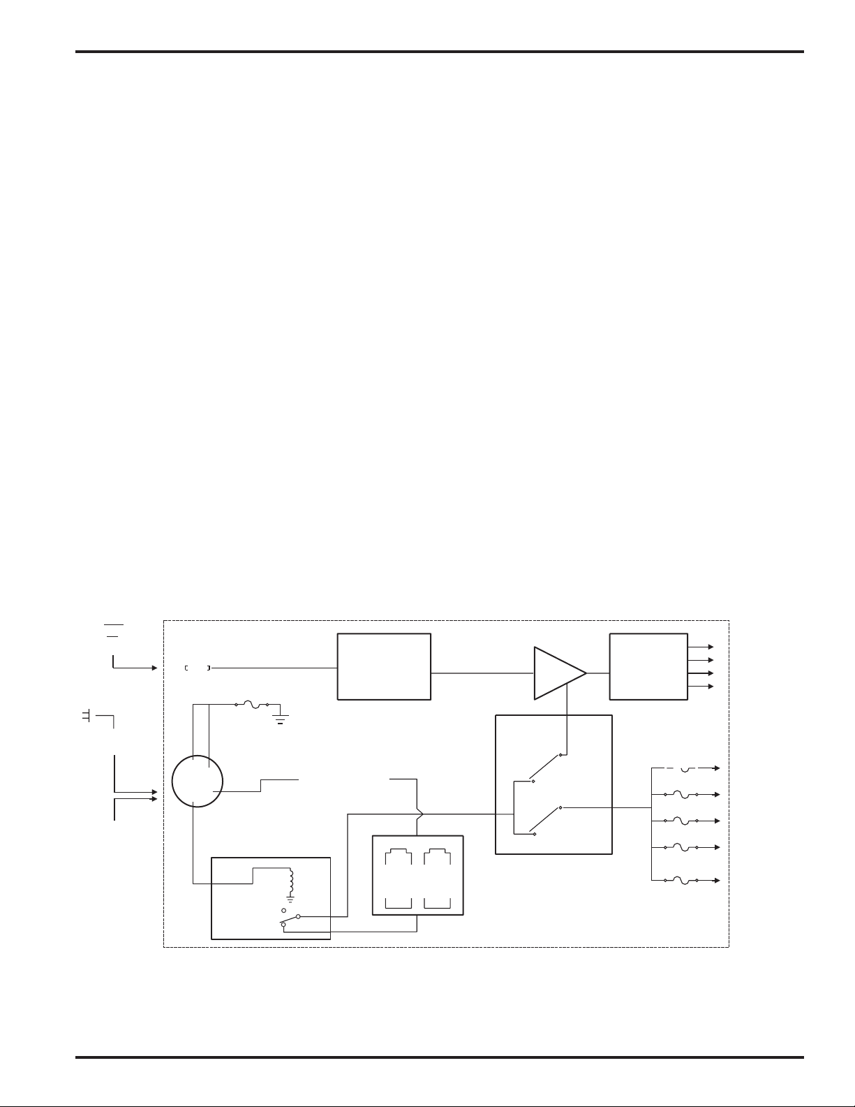
The front end design places RF filtering before gain to minimize intermodulation (IM) products and prevent overload.
Two transmission line ceramic resonators at the input provide filtering with a 50 MHz bandwidth. Following the
resonators is a low noise, low gain RF amplifier designed to evenly compensate for splitter losses in the stage that
follows. A precision splitter/isolator divides the RF signal into four isolated signals, which prevents spurious RF
coupling between receivers. The splitter/isolator is also termination independent, which prevents mismatched or
disconnected RF outputs from affecting the other receivers.
Power can be supplied to the distribution module from four possible sources. The primary source is the gel-cell
battery pack built into the bottom of the housing. Secondly, power may also be provided through an external DC
power source of 12 to 16 VDC of either polarity. When an external source is connected, an internal relay automatically disconnects the internal battery pack. If that DC source fails or is disconnected, the system automatically
reverts to the internal batteries. AC power can be provided through the charger included with the unit. While operating in the AC mode, the internal batteries are also recharged. All power circuits in the distirbution module are
independently protected by internal auto-reset fuses. If the power to one receiver fails, the other receivers will
continue to operate.
120V AC
CH80
EXTERNAL
12V DC
ANTENNA
3
4
1
4
5A
THERMAL
FUSE
2
3
AUTO
SWITCHING
RELAY
FRONT-END
RESONATORS
CHARGING
CIRCUIT
CERAMIC
BUILT-IN
RECHARGEABLE
BATTERIES
RF
AMP
CONTROL
MAIN
SWITCH
SPLITTER
&
ISOLATOR
THERMAL
750mA
FUSES
RF TO
RECEIVERS
12V DC
POWER TO
RECEIVERS
12V DC TO
UDM6S
DISTRIBUTION
MODULE
UDM6 Block Diagram
Rio Rancho, NM – USA
3
Page 4

FRONT PANEL DESCRIPTION
ANTENNA LEADS - These BNC terminated leads provide isolated RF signals for each receiver installed in the
system.
ANTENNA - The antenna provided with the unit attaches to this BNC connector directly with a twist lock motion.
Other 50 Ohm antennas may also be used.
POWER SWITCH - The switch on the front panel of the UDM6 module controls the powering options:
In the EXT (upper) position, the unit will operate only from external power supplied to pins 1 and 4 of the rear panel
4-pin XLR connector.
In the OFF position, all power to the recievers and distribution modules is disconnected, however, the internal
batteries in the Quad Pak can still be charged with the CH80 charger connected to the rear panel 4-pin XLR connector.
In the EXT OR BATT (lowest) position, the system is activated and power will be drawn power from either the gel-cell
batteries located in the bottom of the Quad Pak, or from an external 12 VDC power source if one is connected to the
rear panel 4-pin XLR jack. In this mode, the internal batteries act as a backup of the external power source. If the
voltage from the external power source drops to a level too low for operation, a built-in automatic relay will switch the
external power off and the internal gel-cell batteries on.
EXT LED - This LED will light when power is provided from an external 12 VDC power supply at the rear panel 4-pin
XLR connector.
BATT LED - This LED indicates operation from the internal gel-cell batteries.
CHARGE LED - This LED lights when the gel-cell batteries are being charged with the CH80 charger. It will extin-
guish when the batteries achieve full charge.
AC LED - This LED indicates the unit is plugged into AC with the CH80 charger. It remains on as long as the
charger is connected, regardless of the battery charge state.
INSTALLATION SCREWS - These screws are used for receiver installation and removable. See RECEIVER INSTALLATION for further instructions.
ANTENNA
POWER
UHF RF
DISTRIBUTION
LECTROSONICS
MAIN DIVERSITY
1uV
MOD
RF
MAIN DIVERSITY
1uV
MOD
RF
QUAD UHF
POWER
INT
-42
-36 -30 -12 -18 -24
10uV
POWER
INT
-42
-36 -30
10uV
DIVERSITY
Installation Screws (2)
PILOT
EXT
OFF
-6
0dB
1mV
OFF
100uV
EXT
-12 -18 -24
100uV
0 180
TIGHTEN THESE SCREWS
AFTER INSTALLING THE RECEIVERS
PILOT
-6
0dB
1mV
0 180
Antenna Leads - 4 Main, 4 Diversity
POWER
MAI
MOD
MAIN DIVERSITY
MOD
RF
RF
-42
1uV
POWER
-42 -36 -30 -12 -18 -24
1uV
-36 -30
INT
10uV
INT
10uV
OFF
OFF
PILOT
DIVERSITY N
EXT
-12 -18 -24
-6
0dB
1mV
100uV
PILOT
EXT
-6
0dB
1mV
100uV
LECTROSONICS
0 180
0 180
ANTENNA
EXT
OFF
EXT
OR
BAT
UHF RF/POWER
DISTRIBUTION
CHARGE
LECTROSONICS
Antenna
EXT
Ext Power LED
Power Switch
Bat Power LED
AC
Charging LED
AC LED
4
Page 5

Multi-channel Wireless System
REAR PANEL DESCRIPTION
SERIAL/FREQUENCY LABEL - This label, located on the rear of the housing on each distribution module, indicates
the serial number and the RF passband of the distribution module. IMPORTANT - The receivers installed in the unit
must fall between the passband indicated on the label. Serious signal loss results if the receiver frequencies are
outside the RF passband.
POWER XLR CONNECTOR - This 4 pin Switchcraft D4M connector is the power input jack for both the AC charger
and for external 12VDC power. Pins 1 and 4 are used for external 12 VDC input. Pins 2 and 3 are utilized for 15VDC
charging with the CH80 charger.
POLARITY DIAGRAM - The polarity diagram on the lower panel indicates the wiring connections for the 4 pin XLR
power connector. Use this diagram when connecting your own external power source to the system.
POWER LEADS - These connectors provide power for the individual receivers. Insert the connectors into the jack
provided on each receiver.
INSTALLATION SCREWS - The two large counter-sunk phillips head screws in the central area between the receivers are used for receiver installation and removal. See the following page for further instructions.
RECEIVER AUDIO OUTPUT - Supplies a balanced, low impedance output at microphone or line level. The audio
signal is output on pins 2 and 3, while pin 1 is ground. The output level of this jack is controlled by the OUTPUT
control on the front panel of the receiver and by the range switches in the battery compartments of the receivers (see
receiver instruction manuals). The connector is a standard XLR type.
RECEIVER POWER IN JACK - Connects to the POWER LEAD for powering the receiver from the QUADUHFD
source.
Power XLR
Connector
1
2
3
1:
External Power (–)
2:
CH-80 Charger (–)
3:
CH-80 Charger (+)
4:
External Power (+),
12 to 16 VDC,
0.6 to 2 Amps
UHF RF/POWER
DISTRIBUTION
Installation
Screws
FCC ID: DBZUCR195
Lectrosonics, Inc.
Made in USA
This device complies with
Part 15B of the FCC Rules.
Operation is subject to the
4
condition that this device
does not cause harmful
interference.
FCC ID: DBZUCR195
Lectrosonics, Inc.
Made in USA
This device complies with
Part 15B of the FCC Rules.
Operation is subject to the
condition that this device
does not cause harmful
interference.
1 2
3
TIGHTEN THESE SCREWS LAST
AFTER INSTALLING THE RECEIVERS
1 2 1 2
3
Receiver Audio
Output
FCC ID: DBZUCR195
Lectrosonics, Inc.
Made in USA
Th complies with
is device
Part
the FCC Rules.
15B of
ubjOper
i to the
ation s s ect
device condition that t
his
mful does not caus
e har
interferenc .
e
FCC ID: DBZUCR195
Lectrosonics, Inc.
Made in USA
This device complies with
Part 15B of the FCC Rules.
Operation is subject to the
condition that this device
does not cause harmful
interference.
1 2
3
3
Receiver
Power In Jack
UHF RF
DISTRIBUTION
POWER
INPUT
Polarity
Diagram
1
2
3
EXTERNAL POWER JACK
PIN 1:
PIN 2:
PIN 3:
PIN 4:
4
External Power Ground
CH-80 Charger Ground
CH-80 Charger (+)
Ext Pwr, +12 to 16 VDC, 0.6 to 2 Amps
To
Battery
CHARGING THE INTERNAL GEL-CEL PACK:
Insert CH-80 charger plug into jack on distribution
module rear panel. Charge until green “charging”
LED goes out or longer. Prolonged charging will
not harm the batteries.
LECTROSONICS, INC.
581 Laser RD, Rio Rancho, NM 87124
(800) 821-1121 (505) 892-4501
http://www.lectrosonics.com
Rio Rancho, NM – USA
5
Page 6

RECEIVER INSTALLATION
The QUADUHFD is designed to contain up to four receivers. Installation of these receivers is quite simple. First,
loosen but do not remove, the two large counter-sunk phillips head screws in the front panel and the two in the rear
panel of the housing. (See drawings on previous pages) Insert the receivers, front end first (the end with the antenna connection), in through the rear panel. Seat the front end of the receiver into the recessed lip of the front
panel. Repeat this for each receiver to be installed. After all receivers are in place, hold them in postion and tighten
the front panel screws first. These screws should be fairly snug but excessive force should be avoided and is unnecessary. You are compressing a natural rubber tension tube. Tighten the rear panel screws last. Press firmly on the
front of each receiver to be certain that the receivers are secure.
At the front panel, attach the antenna leads to each receiver, making sure the BNC connector is securely locked into
place. Set the power switch on the receivers to the EXT position. Antenna leads serving empty slots do not need to
be terminated.
At the rear panel, insert the power connectors into the power jack of each receiver. If using battery powered receivers it is recommended that each receiver have a fresh battery in place to serve as backup power in the event that the
internal battery pack or external power source fails for any reason.
OPERATING INSTRUCTIONS
After all the receivers have been installed, check to be sure that the receivers have their power switch set to EXT.
Audio leads should be balanced audio cables leading to the mixer or recorder.
Turn the system on by switching the power switch on the distribution module to EXT or EXT OR BAT. The EXT
position will allow the QUADUHFD to operate ONLY on external power no matter what the external voltage is. If the
voltage of the external power source (not the charger) drops below operational levels, then the system may not
operate. The EXT OR BAT position allows use of an external power source until that source drops below 9V. The
system then switches automatically to the internal batteris of the QUADUHFD. The Charger is not an external power
source in this sense because the charger and the battery are the same buss as far as the UDM6 is concerned. The
power indicator LEDs should light on all the receivers and the distribution modules. If the charger is connected and
plugged into an AC source, the AC and perhaps the CHARGE LEDs will be on as well. If the power source is an
external 12 VDC power supply, the EXT LED will be on.
Operate the wireless microphone according to the instructions included with the wireless systems.
After use, recharge the batteries immediately to prolong their life. The system incorporates industrial quality gel-cells
which can be left on charge 10 days at a time without damage. The charging circuitry will automatically limit the
current flow to the batteries. There are no “memory” problems with these batteries. Charge after every use for
maximum battery life. The CHARGE LED will activate to indicate the batteries are charging and will extinguish
when the batteries are at full charge. The charge rate is 3.5Amps for abut 3 hours falling to a rate of 1 Amp. When
the charge rate drops to 1 Amp, the green LED will reduce brightness to 1/2 and the battery voltage will be 13.8V.
At approximately 16 hours, the unit will acheived full charge. It may be left on charge for a few days without damage
although we do not recommend leaving the system on charge continuously. Important - this unit will achieve an
operational level of charge after 3 hours from a totally dead battery.
The red BAT led will go out when voltage drops to 11.5 volts - approximately 10% battery capacity remains at that
point.
The external 12 VDC power supply may be connected to the system through the 4 pin XLR connector on the rear
panel. The connection is made by supplying the voltage through pins 1 and 4. Pin 1 is negative or ground, pin 4 is
+12V DC.. Polarity is noted on the housing.
6
Page 7

Multi-channel Wireless System
TROUBLESHOOTING
SYMPTOM POSSIBLE CAUSE
NO POWER LEDs OR AUDIO 1) Power switch in the OFF position. Switch to EXT or EXT OR BAT.
POWER LED LIGHTS ON UDM6
BUT NO LIGHTS ON RECEIVERS
NO POWER LEDs, ALL
CONNECTIONS CHECK OK
POWER AND MODULATION LEDs ON,
BUT NO AUDIO
POWER LEDs ON, NO MODULATION LEDs 1) Transmitters not on or in mute position. Check transmitters.
POOR SIGNAL/NOISE OR DROPOUTS 1) Antenna leads not connected, Check antennas.
INTERNAL GEL-CELLS NOT CHARGING 1) Check CH 80 charger - Output voltage should be 15 VDC on
1) Power leads in back not connected to receivers.
Check power connections.
2) Check power switch on receivers.
1) Gel-cell battery charge too low. Either use an external 12 VDC
power supply, or operate on110 to 240 VAC with the CH-80
charger.
1) No audio connection to recorder or mixer. Check
connections.
2) Transmitters have dead batteries, check batteries.
2) Main antenna improperly connected. Check antenna.
3) Antenna “blocked” or in poor RF location. Try moving the
system or the antenna.
4) Transmitter modulation improperly set. Check mod levels.
pin 3, with pin 2 as ground.
Rio Rancho, NM – USA
7
Page 8

SPECIFICATIONS
RF/POWER DISTRIBUTION MODULE
RF Gain: 0 to +1 dB
RF Output: Four outputs, 50 Ohm, BNC
Filtering: Ceramic resonators - 50MHz bandwidth
Third Order Intercept: +27 dBm
Power Input: • 9 to 16 V DC
Pins 1 (gnd) and 4 (+) on XLR power jack
• CH-80 adapter for AC operation, 15V @ 2.8 A
Pins 2 (gnd) and 3 (+) on XLR power jack
Power Consumption: 200 mA at 14V (distribution modules only)
Connectors: • RF: BNC
Short Circuit Protection: Auto-reset thermal fuses (6), 750mA to receivers, 5A to/from
MECHANICAL ASSEMBLY
Construction: Machined aluminum panels, housings, and mechanical parts.
Dimensions: 6.75H x 10.75W x 8.5D inches (in carrying case)
Weight: 22.25lbs. with 4 UCR205D receivers loaded
Batteries: Two 6V, 12 Ah rechargeable gel-cells
Operating Time per Charge: Dependent on receivers installed,
Total draw is dependent on the receiver types involved and
can be as high as two amps total.
• POWER INPUT: 4 pin XLR (Switchcraft D4M)
• POWER OUTPUT: 2.1mm power jack
battery and external DC supply.
8-9 hours with UDR205D’s or UCR300’s
5-6 hours with UCR200’s
14-16 hours with UCR210’s
12-14 hours with UCR195D/UCR195
Specifications subject to change without notice.
This product meets the CE Compliance Standards - EN55022 and
EN50082-1:1998. A copy of the Declaration of Conformity may be
requested from your dealer or by contacting the factory directly:
Lectrosonics, Inc.
Marketing Department
581 Laser Rd. NE, Rio Rancho, NM 87124 USA
tel: 505-892-4501 fax: 505-892-6243 e-mail: marketing@lectrosonics.com
8
Page 9

Multi-channel Wireless System
SERVICE AND REPAIR
If your system malfunctions, you should attempt to correct or isolate the trouble before concluding that the equipment
needs repair. Make sure you have followed the setup procedure and operating instructions. Check out the interconnecting cords and then go through the TROUBLE SHOOTING section in the manual
We strongly recommend that you do not try to repair the equipment yourself and do not have the local repair shop
attempt anything other than the simplest repair. If the repair is more complicated than a broken wire or loose connection, send the unit to the factory for repair and service. Don’t attempt to adjust any controls inside the units.
Once set at the factory, the various controls and trimmers do not drift with age or vibration and never require readjustment. There are no adjustments inside that will make a malfunctioning unit start working.
LECTROSONICS service department is equipped and staffed to quickly repair your equipment. In-warranty repairs
are made at no charge in accordance with the terms of the warranty. Out of warranty repairs are charged at a
modest flat rate plus parts and shipping. Since it takes almost as much time and effort to determine what is wrong
as it does to make the repair, there is a charge for an exact quotation. We will be happy to quote approximate
charges by phone for out of warranty repairs.
RETURNING UNITS FOR REPAIR
You will save yourself time and trouble if you will follow the steps below:
A. DO NOT return equipment to the factory for repair without first contacting us by letter or by phone. We need to
know the nature of the problem, the model number and the serial number of the equipment. We also need a phone
number where you can be reached 8 am to 4 pm (Mountain Standard Time).
B. After receiving your request, we will issue you a return authorization number (R.A.). This number will help speed
your repair through our receiving and repair departments. The return authorization number must be clearly shown
on the outside of the shipping container.
C. Pack the equipment carefully and ship to us, shipping costs prepaid. If necessary, we can provide you with the
proper packing materials. UPS is usually the best way to ship the units. Heavy units should be “double-boxed” for
safe transport.
D. We also strongly recommend that you insure the equipment, since we cannot be responsible for loss of or damage
to equipment that you ship. Of course, we insure the equipment when we ship it back to you.
Mailing address: Shipping address: Telephones:
Lectrosonics, Inc. Lectrosonics, Inc. Regular: (505) 892-4501
PO Box 15900 581 Laser Rd. Toll Free (800) 821-1121
Rio Rancho, NM 87174 Rio Rancho, NM 87124 FAX: (505) 892-6243
USA USA
World Wide Web: http://www.lectrosonics.com Email: sales@lectrosonics.com
Rio Rancho, NM – USA
9
Page 10

LIMITED ONE YEAR WARRANTY
LIMITED ONE YEAR WARRANTY
The equipment is warranted for one year from date of purchase against defects in
materials or workmanship provided it was purchased from an authorized dealer. This
warranty does not cover equipment which has been abused or damaged by careless
handling or shipping. This warranty does not apply to used or demonstrator equipment.
Should any defect develop, Lectrosonics, Inc. will, at our option, repair or replace any
defective parts without charge for either parts or labor. If Lectrosonics, Inc. cannot
correct the defect in your equipment, it will be replaced at no charge with a similar new
item. Lectrosonics, Inc. will pay for the cost of returning your equipment to you.
This warranty applies only to items returned to Lectrosonics, Inc. or an authorized
dealer, shipping costs prepaid, within one year from the date of purchase.
This Limited Warranty is governed by the laws of the State of New Mexico. It states the
entire liablility of Lectrosonics Inc. and the entire remedy of the purchaser for any
breach of warranty as outlined above. NEITHER LECTROSONICS, INC. NOR
ANYONE INVOLVED IN THE PRODUCTION OR DELIVERY OF THE EQUIPMENT
SHALL BE LIABLE FOR ANY INDIRECT, SPECIAL, PUNITIVE, CONSEQUENTIAL,
OR INCIDENTAL DAMAGES ARISING OUT OF THE USE OR INABILITY TO USE
THIS EQUIPMENT EVEN IF LECTROSONICS, INC. HAS BEEN ADVISED OF THE
POSSIBILITY OF SUCH DAMAGES. IN NO EVENT SHALL THE LIABILITY OF
LECTROSONICS, INC. EXCEED THE PURCHASE PRICE OF ANY DEFECTIVE
EQUIPMENT.
This warranty gives you specific legal rights. You may have additional legal rights which
vary from state to state.
LECTROSONICS, INC.
581 LASER ROAD
RIO RANCHO, NM 87124 USA
www.lectrosonics.com
April 1, 2003
 Loading...