

Page 1
Digital IEM System
INSTRUCTION MANUAL
TM
Fill in for your records:
Serial Number:
Purchase Date:
Rio Rancho, NM, USA
www.lectrosonics.com
Page 2

QUADRA
2
LECTROSONICS, INC.
Page 3

Table of Contents
FCC Notice ............................................................................... 4
Industry Canada Notices ........................................................ 4
Safety Notes............................................................................. 4
System Overview..................................................................... 5
Digital IEM System
Receiver
Receiver Operation.................................................................. 6
Battery Insertion..................................................................... 6
Powering the Unit ON and OFF ............................................. 6
Control Panel/Knobs .............................................................. 6
Body Placement....................................................................... 7
LCD Boot Screens................................................................... 7
Selecting 2 Channel or 4 Channel Operation........................ 7
2 Channel Operation ............................................................... 8
4 Channel Operation ............................................................... 9
Split 1,2 Operation................................................................. 10
Split 3,4 Operation................................................................. 11
Single Channel Operation..................................................... 12
Additional Setup Options ..................................................... 13
Tune ..................................................................................... 13
Pan ....................................................................................... 13
Limiter .................................................................................. 14
Backlight .............................................................................. 14
Treble Shelf .......................................................................... 14
Lock Setup........................................................................... 14
Factory Defaults................................................................... 15
Using the Presets .................................................................. 15
Load..................................................................................... 15
Save ..................................................................................... 16
Clear .................................................................................... 16
None .................................................................................... 16
Replacement Parts ................................................................ 17
Transmitter
Transmitter Front Panel .....................................................18
Transmitter Rear Panel.......................................................18
Initial Setup ......................................................................... 19
Powering the Unit
ON and OFF .................................................................19
LCD ......................................................................................19
Audio Signal Monitoring ....................................................19
Transmitter Menus.............................................................. 20
Selecting 2 Channel
or 4 Channel Operation.....................................................20
Tuning ...............................................................................20
Input Type..........................................................................20
Audio Trim ......................................................................... 21
Lock Setup........................................................................21
Factory Default Reset .......................................................21
Rack Mount Hardware........................................................ 22
Dual Unit Rack-Mount Instructions...................................22
Single Unit Rack-Mount Instructions................................24
Replacement Parts ............................................................. 26
System
Firmware Updates ..............................................................27
Troubleshooting Guide ......................................................28
Service and Repair ............................................................. 29
Returning Units for Repair ................................................29
Specifications .....................................................................30
Warranty .............................................................. Back Cover
Rio Rancho, NM
3
Page 4

QUADRA
FCC Notice
NOTE: This equipment has been tested and found
to comply with the limits for a Class B digital device,
pursuant to Part 15 of the FCC Rules. These limits
are designed to provide reasonable protection against
harmful interference in a residential installation. The
equipment generates, uses and can radiate radio
frequency energy and, if not installed and used in
accordance with the instructions, may cause harmful
interference to radio communications. However, there
is no guarantee that interference will not occur in a
particular installation. If this equipment does cause
harmful interference to radio or television reception,
which can be determined by turning the equipment
off and on, the user is encouraged to try to correct the
interference by one or more of the following measures:
• Reorient or relocate the receiving antenna
• Increase the separation between the equipment
and receiver
• Connect the equipment into an outlet on a circuit
different from that which the receiver is connected
• Consult the dealer or an experienced radio/TV
technician for help
Changes or modifications to this equipment not expressly approved by Lectrosonics, Inc. could void the
user’s authority to operate it.
Industry Canada Notices
Operation of this device is subject to the following two
conditions: (1) this device may not cause interference,
and (2) this device must accept interference, including
interference that may cause undesired operation of the
device.
This device has been designed to operate with the
antenna listed below, and having a maximum gain of 6
dB. Antennas not included in this list or having a gain
greater than 6 dB are strictly prohibited for use with
this device. The required antenna impedance is 50
ohms.
• Lectrosonics M4T Antenna; P/N AMJR-915
To reduce potential radio interference to other users,
the antenna type and its gain should be so chosen that
the equivalent isotropically radiated power (e.i.r.p.) is
not more than that permitted for successful communication.
Safety Notes
Excessive sound levels can cause permanent hearing
damage.
1. Always adjust the volume to the lowest level before
listening to unknown transmissions.
2. Use the lowest reasonable level consistent with
hearing safety.
3. Don’t use high sound levels in the earphone to
overcome high ambient sound levels. That is
absolutely foolish! Demand and use high isolation
earphones.
4. Don’t expose your ears to sound levels that cause
them to ring. If your ears do ring after exposure,
think of it as a warning bell telling you not to do
that again.
OSHA (Occupational Safety Health Administration)
guidelines on the maximum allowable time exposure to
sound pressure levels that will cause hearing damage
are as follows:
8 hours at 90 dB SPL
4 hours at 95 dB SPL
2 hours at 100 db SPL
1 hour at 105 dB SPL
30 mins at 110 dB SPL
15 mins at 115 dB SPL
NEVER expose your ears to 120 dB SPL or higher!
Damage will occur.
4
LECTROSONICS, INC.
Page 5

Digital IEM System
4 CHANNEL MODE
System Overview
The Quadra system provides an entirely new level
of audio and RF performance in a wireless monitor
system. The combination of analog or digital input
capability, ultra-low latency 24 bit, 48 kHz audio, digital
RF modulation and discrete four channel mixing capability make the Quadra a truly unique IEM product for
mission-critical, professional applications.
The system is designed for line level analog audio
signals and AES/EBU digital audio input signals.
48kHz/24-bit audio, ruler-flat 20Hz to 20kHz frequency
response, ultra-low distortion and high dynamic range
assure excellent audio quality. Housings and panels
are machined aluminum with electrostatic powder
coated and anodized finishes and laser etched marking for durability. An intuitive mixing interface and
comprehensive LCD on the belt pack receiver provide
performing artists and monitor engineers alike with a
comfortable and confident user experience.
M4 Transmitter
The half-rack transmitter can accept up to four inputs
from digital or analog sources. The inputs can be configured as follows:
The input connectors are full size balanced XLR types
for AES/EBU and balanced line level analog signals.
Input preamp circuits use a special balanced amplifier
with very high common mode rejection to minimize
hum and noise.
Either analog or AES/EBU digital input signals are
converted to an internal 24-bit digital format which is
then encoded, organized into packets, and passed to
an RF modulator using spread spectrum techniques
and error correction for robust reception. The modulated RF signal is filtered before and after amplification
to suppress out-of-band noise and spurious signals,
and a circulator/isolator guards against intermodulation
interference (IM).
The transmitter can be free-standing or rack-mounted
in single units (via an optional rack mounting kit) or in
a dual configuration using supplied hardware.
A USB port is provided for firmware updates.
• Four analog inputs using all four jacks
• Two digital inputs using jack 1 and two balanced
analog inputs using jacks 3 and 4
• Four digital inputs using jacks 1 and 2
M4 Receiver
The receiver employs advanced antenna switching
diversity reception, switching between the antennas
during packet headers in order to maintain a seamless
audio signal. A configurable four-channel mixer on the
top of the receiver housing allows the user to mix four
discrete audio channels according to the needs of the
performance. The headphone jack is fed from a highquality stereo amplifier with adequate power to drive
headphones or earbuds to sufficient levels for stage
performance or other environments with significant
background noise. A high-density, backlit LCD allows
the user to make setup changes via the available
menu options.
A USB port is provided for firmware updates.
Frequency Range
Using the license free 902 - 928 MHz ISM band, this
system is outside the normal broadcast frequencies
thus providing both technical and operational advantages over standard analog systems.
Freq 1
OR
Freq
Freq
1A
1B
Freq 2
OR
Freq
Freq
2A
2B
2 CHANNEL MODE
Freq
3A
Freq 3
OR
Freq
3B
Freq
4A
Freq 4
OR
Freq
4B
In four-channel mode, the system occupies 4 MHz and
is selectable between four available center frequencies: 907.776, 912.384, 916.992 and 923.904 MHz.
In two-channel mode, Quadra occupies 2 MHz and
is selectable between eight available center frequencies: 906.624, 908.928, 911.232, 913.536, 915.840,
918.144, 922.752 or 925.056 MHz.
Multi-Channel Capability
Quadra can be configured to provide either 2 or 4
audio channels. In the 2-channel mode, eight different
frequencies are available, each with two audio channels. In the 4-channel mode, four different frequencies
are available, each with four audio channels. Multiple
Quadra systems can be operated in the same location
to provide up to 16 total audio channels between all
units.
The performer can then use the on-board mixer to tailor the audio output to his or her tastes or the requirements of the performance at hand.
Rio Rancho, NM
5
Page 6
QUADRA
Receiver Operation
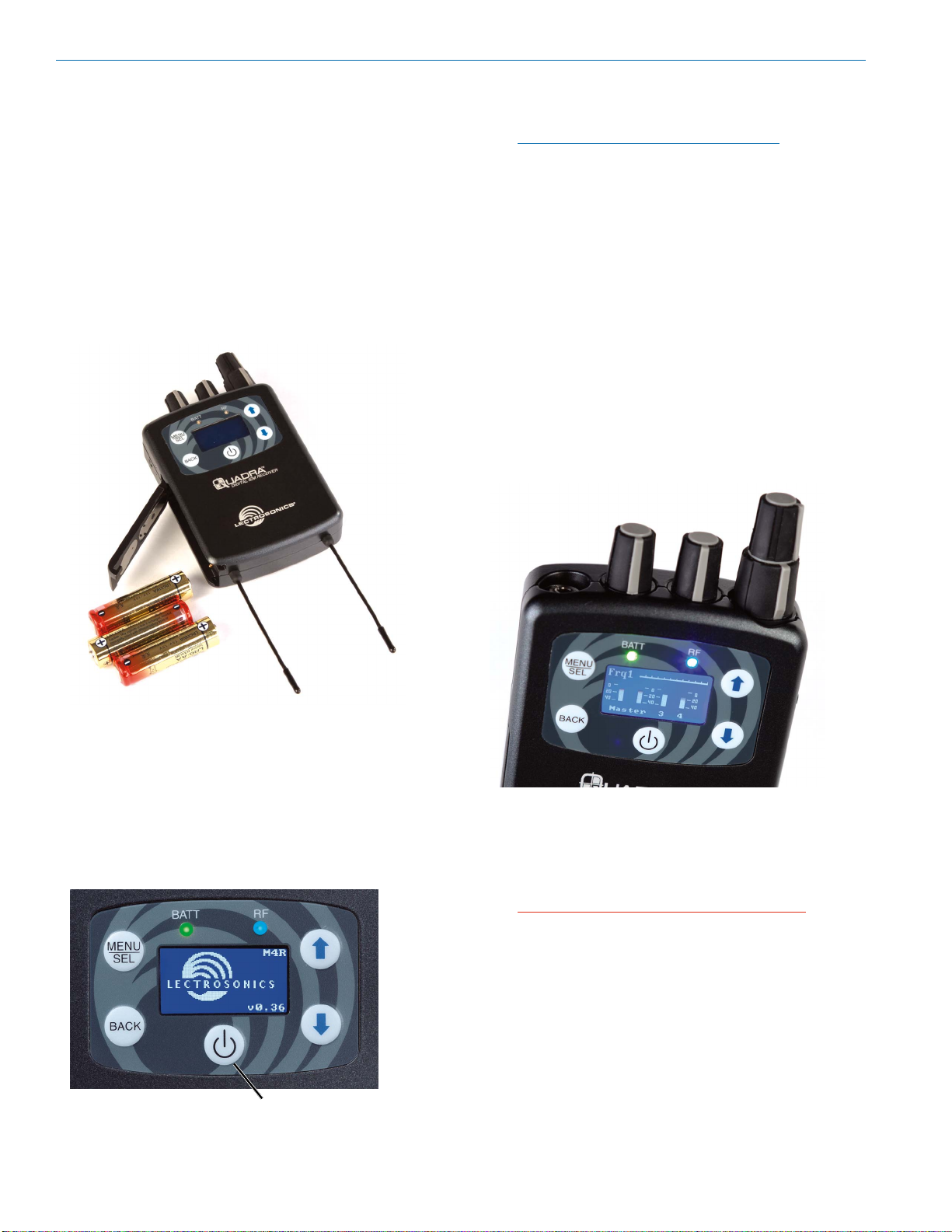
Battery Insertion
The receiver is powered by three AA batteries, either
alkaline, lithium, or rechargeable types. Do not use
“heavy duty” batteries from a drug store - they will not
last long in the M4 receiver.
Open the battery door by pressing on it while sliding it
downward. It should then flip open allowing full access
to the battery compartment. Carefully note the battery
orientation as indicated by the diagrams inside. The
outer two batteries are positive (+) facing in, while the
middle battery is positive (+) facing out.
After the Power Up Sequence is displayed briefly, the
Main Window appears and the M4R is ready for operation.
Note also that the BAT T LED should be lit.
Green indicates good power. Red indicates your
batteries are 2/3 depleted. Flashing red indicates
that you should replace your batteries as soon as
possible.
To turn the receiver off, press and hold the power button for three seconds. A countdown will be displayed
until the power is turned off.
Control Panel/Knobs
The four knobs on the top edge of the M4 receiver
(two are in a dual concentric arrangement and two are
separate) allow for a number of mixer configurations
by using the Chan. Setup in the LCD menu. The first
knob (the tall, skinny one) is usually set as a Master
Volume, while the other three can be set up differently
depending on the artist’s needs and preferences. See
Selecting 2 Channel or 4 Channel Operation below
for details.
Once the three batteries are in place, close the door
by swinging it shut then sliding it upwards while applying slight pressure. It should snap shut and line up with
the case.
Powering the Unit ON and OFF
Press the power button once to turn on the unit. Check
to see that the LCD displays the single screen Power
Up Sequence showing the company logo, model number and firmware revision.
Power Button
The headphone jack is a standard 1/8” stereo TRS (tip,
ring, sleeve) jack with standard headphone wiring (tip
is left, ring is right, sleeve is ground). The headphone
amp can deliver 200mW into a 32 Ohm load so it is
important to always start with the volume low before
plugging in your headphones or earbuds.
CAUTION: Hearing damage can result from
listening too loudly with this receiver!
6
LECTROSONICS, INC.
Page 7

Body Placement
Position the receiver on a belt, guitar strap, wardrobe,
etc. so that the antennas are oriented vertically and not
touching a metallic surface. Make sure the antennas
are on the outside of thick or metallic costuming so the
antenna whips will be out in the open. For maximum
receive sensitivity, it is good practice to keep the antenna whips from direct contact with a person’s body.
Digital IEM System
To access the setup menus, press the MENU/SEL
button at the upper left of the membrane panel. Press
the BACK button to back up one level or return to the
main window. The UP and DOWN arrow buttons along
the right side of the control panel allow you to navigate
between menu options and to adjust specific parameters within the setup screens.
Battery status is indicated by a GREEN LED. The
LED turns RED to indicate that your batteries are 2/3
depleted. FLASHING RED indicates that you should
replace your batteries as soon as possible.
LCD Boot Screens
The boot sequence will briefly display the company
logo, model number and firmware revision.
If a preset is active, this screen will appear, including
the word (modified) if the preset has been edited.
Following the boot-up sequence, the receiver will revert to the Main Window, showing the following:
Operating
Frequency
RF Level Meter
Audio
Level
Meters
The blue RF LED indicates an RF lock between the
transmitter and receiver, when lit.
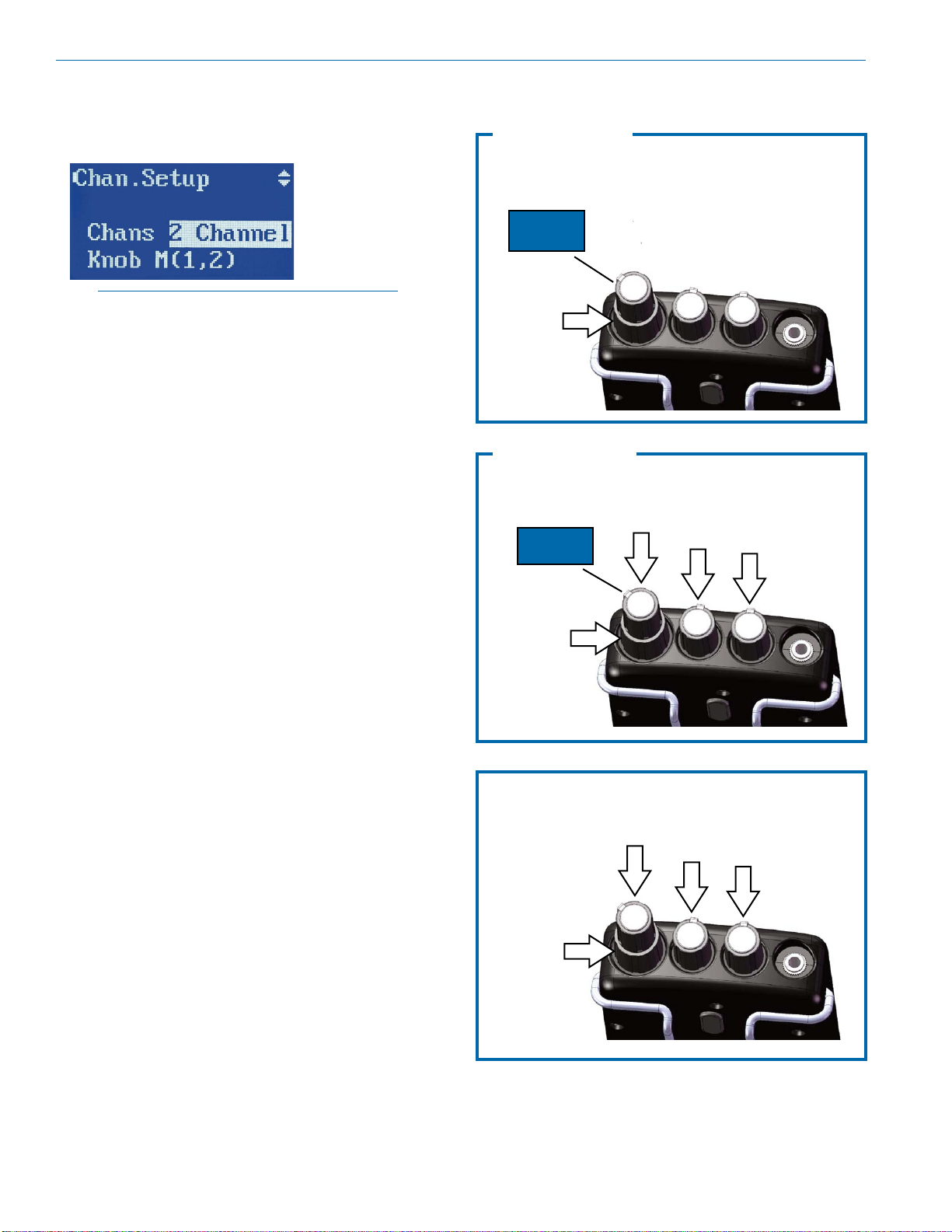
Selecting 2 Channel
or 4 Channel Operation
The Chan. Setup screen allows you to select whether
the receiver operates in 2 channel, 4 channel or split 4
channel modes, and then how the knobs on the top of
the receiver are configured as a mixer.
Each Chan. Setup screen allows selection of 2 Channel and 4 Channel modes, plus a second line for selection of the knob configurations.
2/4 channel
selection
knob
configuration
Press MENU/SEL to toggle the highlight between the
Chans and Knob lines and use the UP and DOWN
arrow keys to make selections.
Operating Mode and
Knob Configuration
Rio Rancho, NM
NOTE: Review the individual setup options in the
following section.
7
Page 8
QUADRA
2 Channel Operation
In this mode, two channels are fed to the transmitter
and are available at the receiver.
Master(1,2) mode
AUDIO CH.
1
MASTER
VOLUME
2
NO
FUNCTION
NOTE: the transmitter must be also in 2 Channel
mode for the receiver to operate in this manner.
2-ch. mode allows for three different knob setups:
• Master(1,2)
This is the factory default and is equivalent to
standard IEM systems where only a stereo signal
is used. The tall, thin knob is the stereo master
volume.
• Master(1)+2
Feeds audio channel 1 to the master volume
(tall, thin knob) and audio channel 2 to the lower
concentric knob for independent control. You can
develop a stereo mix by panning each channel in
the stereo field (see panning, below).
• 1+2
Gives you individual control over both audio
channels. Audio channel 1 is fed to the tall thin
knob, and audio channel two is fed to the lower
concentric knob. In this setup, there is no master
volume knob.You can develop a stereo mix by
panning each channel in the stereo field (see panning, p. 10).
NO
FUNCTION
Master(1)+2 mode
MASTER
VOLUME
AUDIO
CH. 2
MASTER
VOLUME
AUDIO
CH. 1
NO
FUNCTION
8
1+2 mode
AUDIO
CH. 2
AUDIO
CH. 1
NO
FUNCTION
LECTROSONICS, INC.
Page 9
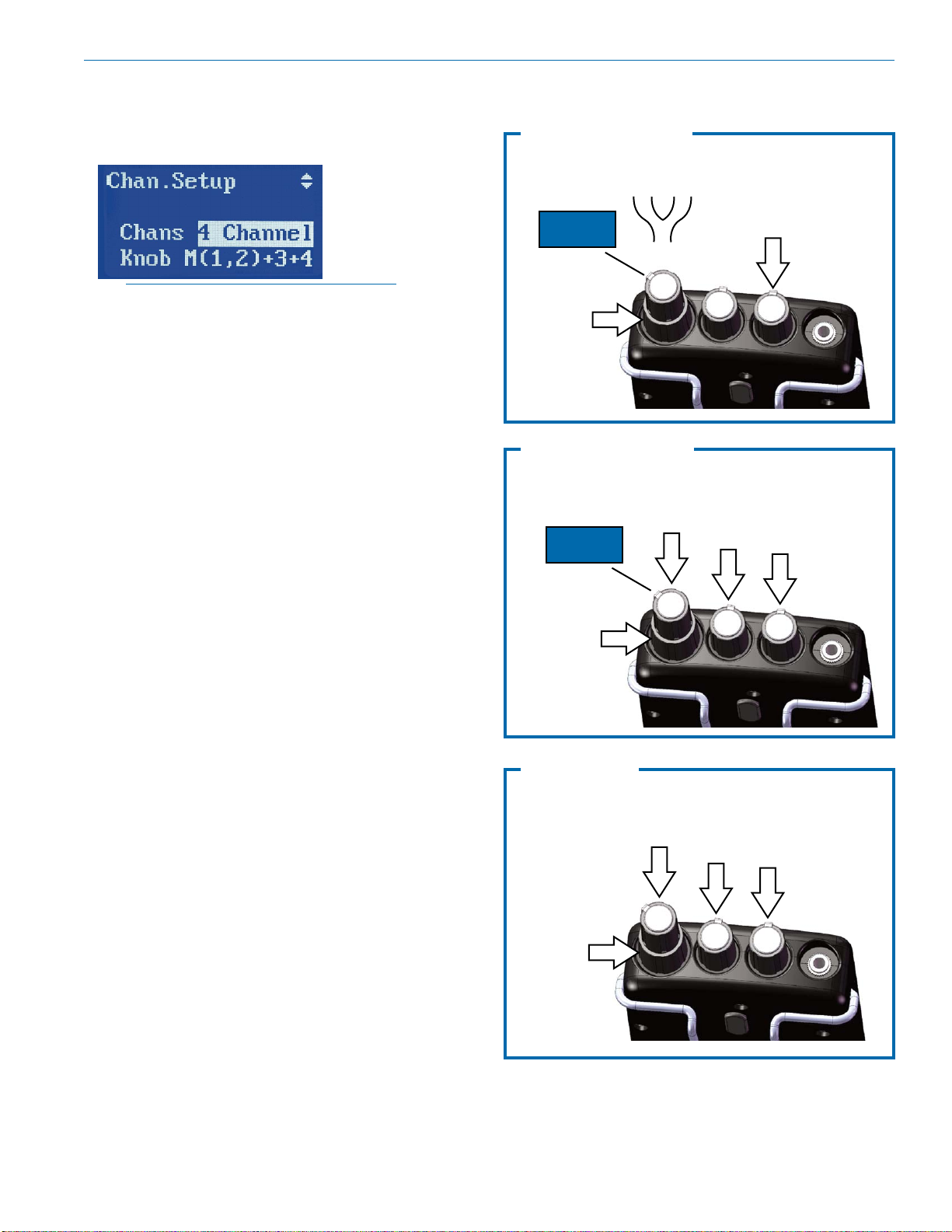
4 Channel Operation
In this mode, all four audio channels fed to the transmitter are available at the receiver.
Master(1,2)+3,4 mode
AUDIO CH.
1
MASTER
VOLUME
2
Digital IEM System
AUDIO
CH. 3
AUDIO
CH. 4
NOTE: the transmitter must be in 4 Channel
mode for the receiver to work in this manner.
Audio can be routed to the four audio control knobs in
the following ways:
• Master(1,2)+3,4
Feeds channels 1 & 2 to the master volume knob
in a fixed stereo relationship, while audio channels 3 & 4 are on the two smaller separate knobs.
This gives you individual control over two of the
channels in their relationship to the stereo mix.
For instance, you may want to have drums and
bass (in stereo) on 1 & 2, your guitar in ch. 3 (first
small knob, in the middle) and your vocals in ch.
4 (second small knob, closest to the headphone
jack). After choosing this mode, you would use
the master knob to control your overall volume,
and the other two knobs to change how those two
individual channels are mixed into the master.
• Master(1)+2, 3, 4
Places ch. 1 on the master knob, and then gives
you individual control over channels 2, 3 and 4.
Use this mode if you plan to have a mono mix as a
starting point, and then add three additional channels that you would like to adjust during performance. An example would be drums and bass (in
mono) on 1, backing vocals on 2, your guitar on
3, and your vocals on 4. Each of the channels can
still be panned in the stereo field.
• 1+2+3+4
Gives you individual control over all four audio
channels. In this setup, there is no master vol-
ume knob. You can develop a stereo mix by panning each channel in the stereo field (see panning,
below).
NO
FUNCTION
Master(1)+2,3,4 mode
AUDIO
CH. 1
MASTER
VOLUME
AUDIO
CH. 2
AUDIO
CH. 3
AUDIO
CH. 4
1+2+3+4 mode
AUDIO
CH. 1
AUDIO
CH. 3
AUDIO
CH. 4
Rio Rancho, NM
AUDIO
CH. 2
9
Page 10
QUADRA
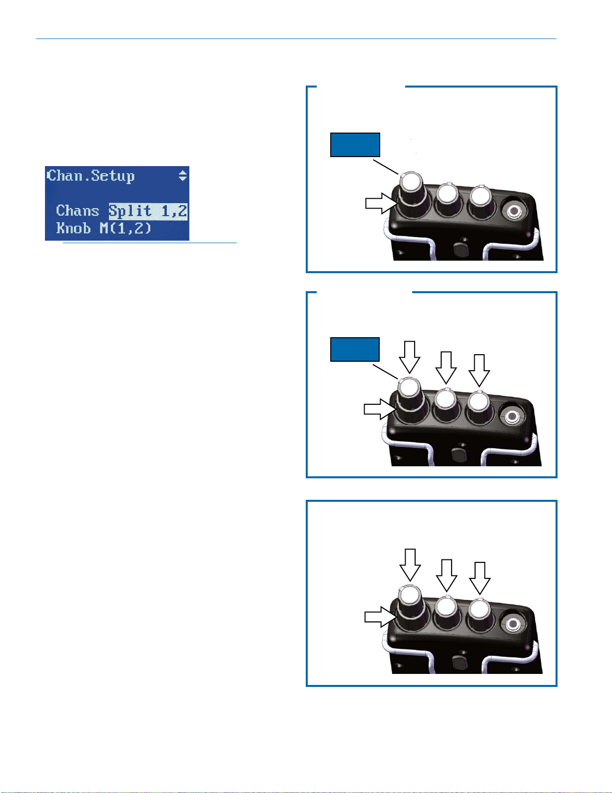
Split 1,2 Operation
Split modes allow you to use a single M4T transmitter
running in the 4 Channel mode to send two different
2 channel stereo mixes to two different receivers or
groups of receivers using a single radio frequency.
Split 1+2 mode delivers audio channels 1 and 2 to
the tall, thin knob and the lower concentric knob. The
knobs can be set up to function in three different ways.
NOTE: the transmitter must be in 4 Channel
mode for the receiver to work in this manner.
• Master(1,2)
Equivalent to standard IEM systems where only
stereo signal is used. The tall, thin knob is the stereo master volume and is fed from audio channels
1 & 2. Although there is audio on channels 3 & 4
in the transmission itself, they are muted and thus
the lower main knob and two individual knobs do
not function.
• Master(1)+2
Feeds audio channel 1 to the master volume (tall,
thin knob) and audio channel 2 to the lower concentric knob for independent control.
• 1+2
The two knobs function independently with neither
one working as a master. Feeds audio channel 1
to the tall, thin knob and audio channel 2 to the
lower concentric knob for independent control.
Master(1,2) mode
AUDIO CH.
1
MASTER
VOLUME
NO
FUNCTION
Master (1)+2 mode
AUDIO
CH. 1
MASTER
VOLUME
AUDIO
CH. 2
2
FUNCTION
NO
FUNCTION
NO
NO
FUNCTION
10
1+2 mode
AUDIO
CH. 2
AUDIO
CH. 1
NO
FUNCTION
LECTROSONICS, INC.
NO
FUNCTION
Page 11

Split 3,4 Operation
Split modes allow you to use a single M4T transmitter
running in the 4 Channel mode to send two different
2 channel stereo mixes to two different receivers or
groups of receivers using a single radio frequency.
Split 3+4 mode delivers audio channels 3 and 4 to
the tall, thin knob and the lower concentric knob. The
knobs can be set up to function in three different ways.
NOTE: the transmitter must be in 4 Channel
mode for the receiver to work in this manner.
• Master(3,4)
Also equivalent to standard IEM systems where
only stereo signal is used. The tall, thin knob is
the stereo master volume and is fed from audio
channels 3 & 4. Here, although there is audio on
channels 1 & 2 in the transmission itself, they are
muted and thus the two individual knobs do not
function.
• Master(3)+4
Feeds audio channel 3 to the master volume (tall,
thin knob) and audio channel 4 to the lower concentric knob for independent control.
• 3+4
The two knobs function independently with neither
one working as a master. Feeds audio channel 3
to the tall, thin knob and audio channel 4 to the
lower concentric knob for independent control.
Master(3,4) mode
AUDIO CH.
3
MASTER
VOLUME
NO
FUNCTION
Master (3)+4 mode
MASTER
VOLUME
AUDIO
CH. 4
AUDIO
CH. 3
4
FUNCTION
NO
FUNCTION
Digital IEM System
NO
NO
FUNCTION
Rio Rancho, NM
3+4 mode
AUDIO
CH. 4
AUDIO
CH. 3
NO
FUNCTION
NO
FUNCTION
11
Page 12

QUADRA
Single Channel Operation
The Single mode allows you to use one M4T transmitter running in the 4 Channel mode to send up to four
mono mixes to up to four different receivers or groups
of receivers using a one radio frequency.
This delivers the selected audio channel to the tall, thin
knob as the master volume. Any one of the four audio
channels sent to the transmitter can be routed to the
master knob. The other three knobs have no function.
NOTE: the transmitter must be in 4 Channel
mode for the receiver to work in this manner.
Press MENU/SEL to select the Knob menu item.
M(2)
MASTER
VOLUME
NO
FUNCTION
M(3)
AUDIO
CH. 2
NO
FUNCTION
NO
FUNCTION
Select desired
audio channel
Use the UP and DOWN arrows to select the desired
channel.
The knob configuration is the same for all four audio
channel selections. The only difference is which audio
channel is delivered to the headphone jack and controlled by the tall, thin knob.
M(1)
AUDIO
CH. 1
MASTER
VOLUME
NO
FUNCTION
NO
FUNCTION
NO
FUNCTION
MASTER
VOLUME
NO
FUNCTION
M(4)
MASTER
VOLUME
NO
FUNCTION
AUDIO
CH. 3
AUDIO
CH. 4
NO
FUNCTION
NO
FUNCTION
NO
FUNCTION
NO
FUNCTION
12
LECTROSONICS, INC.
Page 13

Additional Setup Options
Digital IEM System
Tune
To select your RF operating frequency, choose Tune in
the menu list, and press the MENU/SEL button.
Here, you can choose between four operating frequencies in the 4 Channel mode or one of the Split modes,
or eight operating frequencies the in 2 Channel mode.
You should test your proposed frequency by first
ensuring that your transmitter is turned off and then
observing the RF level in the LCD on your receiver in
the main window.
RF signal strength is indicated
by this status bar.
Pan
To select your overall stereo balance and stereo panning for individual audio channels, use the arrow buttons to highlight Pan in the menu list.
Press the MENU/SEL button to enter the setup screen.
The setup screen that appears will be determined
by the 2 channel or 4 channel mode and the knob
configuration you have selected. Continue pressing
MENU/SEL to select the channel, then use the UP and
DOWN arrows buttons to adjust the balance.
Note: All channels panned center and stereo
balance centered is the factory default setting.
In a mode that defines a Master knob, the uppermost
channel line is labled BAL.
If you see a large RF signal at the receiver and your
transmitter is off, you may want to choose a different
operating frequency to attain as much operating range
as possible.
Note: Frequency 1a at 906.624 MHz is the
factory default setting.
Once you have selected an operating frequency, press
the BACK button to return to the main menu list. As
soon as you turn on your transmitter (see transmitter section), place it in the correct mode (2 ch. vs. 4
ch.) and then tune it to the same frequency as your
receiver/s, you should see the blue RF LED light on
your receiver/s. This indicates you have a signal lock
between the transmitter and receiver.
Use the MENU/SEL button to move between master
balance and the available audio channels.
Press MENU/SEL
to select channel
(highlight)
For stereo balance (when available), use either the
arrow keys or the lower concentric knob to adjust the
desired L-R balance.
Use UP and DOWN
buttons or lower
concentric knob to
pan the highlighted
channel
For individual channels (when available), use either
the arrow keys or the lower concentric knob to pan the
channel to the desired position in the stereo field.
Once you have completed the necessary adjustments,
press the BACK button to exit this screen and return to
the main menu.
Rio Rancho, NM
13
Page 14

QUADRA
Limiter
This feature can be used in order to provide audio limiting at the receiver in order to prevent excessive levels
at the headphones or earbuds. To set the amount of
limiting, highlight “Limiter” in the menu list using the arrow keys. Press MENU/SEL to choose this function.
Use the arrow keys to select the limiter threshold in
3 dB increments. Test it with a known signal to determine the maximum sound level you are comfortable
with. The pre-gain setting can then be used to boost
the audio level ahead of the limiter. Use this feature if
you need to make up for weaker audio input levels at
the transmitter. Use the MENU/SEL button to choose
“Pregain”, then use the arrow buttons to adjust in 3 dB
increments.
Pre-Gain
This adjustment is used in conjunction with the Limiter setting to control the overall dynamic range ot the
audio being heard. As the Pregain setting is increased
and the Threshold setting is decreased, the dynamic
range is compressed as shown in the diagram. When
set for maximum compression, the audio being heard
will be at the same loudness regardless of how loud
the input signal becomes.
Treble Shelf
In this screen, you can choose a treble boost with a
corner either at 5kHz or 7kHz, and a boost of up to 9
dB in 3 dB increments. Treble shelf can be used to
compensate for a stereo mix that is lacking high frequency information, or earbuds that “roll off” too early
in the high frequency area.
This high-frequency boost should be used sparingly
due to the fact that it can accelerate hearing loss with
high volumes in the earphones or headphones.
Note: the factory default setting is 5 kHz corner
with 0dB boost.
Lock Setup
This feature is used to lock the control panel so that
no further changes can be made, other than normal
adjustments to the upper mixing knobs. Once Locked
is selected, note that a small lock icon appears in the
upper right of each setup menu screen. With the receiver locked, you can view each menu screen but you
are unable to make changes and the power can not be
turned off.
-0 dB
-3 dB
-6 dB
-9 dB
-12 dB
-15 dB
-18 dB
+12 dB
+9 dB
+6 dB
+3 dB
OUTPUT LEVEL
PRE-GAIN
THRESHOLD
INPUT LEVEL
Backlight
The backlight control page allows you to select the
length of time before the backlight turns off on the receiver. The factory default setting is 5 minutes, but you
can also select 30 seconds or Always on.
To return to the unlocked status, go back to the Lock
Setup screen via the main menu, and select Unlocked. Also, note that the Locked status is main-
tained even if the batteries are changed.
14
LECTROSONICS, INC.
Page 15

Digital IEM System
Factory Defaults
This is used if you intend to reset the receiver back to
factory settings. Select Defaults on the main menu
and press MENU/SEL to select the two choices.
Default Setup restores the factory settings, but leaves
User Presets intact. Factory Wipe restores the factory
settings and deletes the stored User Presets.
Factory Default Settings:
• 4 Channel operation
• M (1,2)+3+4 knob setup
• RF Frequency 1 (907.776 MHz)
• Limiter at 0 dB threshold
• Pre-Gain at +0 dB
• Backlight: off at 5 minutes
• Treble Shelf: 5 kHz corner, +0 dB
• Unlocked
After using the MENU/SEL to select the appropriate
default operation, press MENU/SEL to continue the
operation.You will be asked to confirm this step - you
must use the arrow keys to select Yes, followed by
pressing the MENU/SEL once again. Defaults Re-
stored or Factory Initialized will be briefly shown on
the LCD, depending on which version of the default
operation was chosen. This indicates the process is
complete. If you have selected “Factory Wipe”, the
receiver will also re-boot and return to the main operating screen.
Using the Presets
Presets can be used to store all user settings including Channel Setup, knob configuration, panning, and
operating frequency. Five factory presets give you the
most common starting configurations, while eight user
presets allow you to customize your receiver and store
those detailed settings. This may be particularly useful
for monitor engineers who may wish to have a “copy”
of each musician’s settings in their own receiver pack.
Select Presets in the main menu and press MENU/
SEL to enter the submenu.
Four menu items are available in the sub-menu to
save, retrieve and delete stored settings: Load, Save,
Clear and None.
Load
To retrieve a factory preset or a previously saved user
preset, use the arrow buttons to select Load. Press the
MENU/SEL button to select this function.
The current Preset will be displayed
here. If no Preset is in use, the
character will be replaced by a
double dash symbol ( – – ).
Rio Rancho, NM
Once in the Load from screen, use the UP and
DOWN arrow buttons to select from the five Factory
Presets and the eight User Presets. Unused preset
slots will be indicated as (empty).
15
Page 16

QUADRA
The first five presets, A - E, are permanently loaded
with the most common channel setup and knob configuration combinations:
Factory A: 4-channel, M(1,2)+3+4 (see p. 9)
Factory B: 4-channel, M(1)+2+3+4 (see p. 9)
Factory C: 2-channel, M(1,2) (see p. 8)
Factory D: split 1, 2, M(1,2) (see p. 10)
Factory E: split 3, 4, M(3,4) (see p. 11)
Factory presets can be modified by changing the knob
setup, panning or any other parameter and then saved
as a user preset for later recall.
If you have modified a preset without saving it, this will
be indicated with an asterisk (*) next to the preset letter or number on the bootup sequence and also at the
lower left on the main Preset menu page.
Save
To save your current settings as a user preset, use
the arrow buttons to select Save. Press MENU/SEL to
choose this function.
Yes stores the frequency in the preset. No does not.
Once you have selected whether or not you wish to
store the frequency into the preset, press MENU/SEL
to complete the process. The LCD will briefly display
Saving Preset X, with (or without) frequency. The
save process is now complete.
NOTE: Saving to an existing User Preset will
overwrite the previously saved settings.
Clear
If you need to clear the contents of a user preset, use
the arrow buttons to select Clear. Press MENU/SEL to
choose this function.
Once in the Clear slot screen, use the UP and DOWN
arrow buttons to select one of the eight user presets.
User will appear next to the slot number for presets
which have been previously saved. (empty) will appear
in slots that are not being used.
Once in the Save into screen, use the UP and DOWN
arrow buttons to select one of the eight user presets.
User will appear next to the slot number for presets
which have been previously saved. (empty) will appear
in slots that are not being used.
Press MENU/SEL To complete the process. The
screen will then display Save Preset X with Freq?
Use the UP and DOWN arrows to select whether or
not you wish to save your operating frequency into this
preset.
To complete the Clear process, Press MENU/SEL.
The screen will then display Clearing Preset X. The
process is now complete.
None
If you prefer not to use a preset, use the arrow buttons
to select None. Press MENU/SEL to choose this function and press MENU/SEL to operate without presets.
16
LECTROSONICS, INC.
Page 17

Accessories
P/N 25984 replacement wire belt clip.
CCM4R Foam lined carrying case.
Digital IEM System
BCHINGED Spring-loaded belt clip kit
P/N 35747
rubber cushion
P/N 35856
Hex key wrench
(allen wrench)
P/N 28852 4-40 x 1/4
flat hex head screw
Rio Rancho, NM
17
Page 18

QUADRA
Transmitter Front Panel
DIGITAL IEM
Headphone Channel Select Buttons Power
Monitor Switch
TM
Transmitter Rear Panel
Antenna Output
ANT
USB
100-240 VAC, 50/60 Hz, 5W
Power Inlet Digital Audio
100-240 VAC, Firmware Updates Inputs
50/60 Hz, 5 W
S/N
USB Port for
Analog Audio Inputs
4
DIGITAL IEM TRANSMITTER
AES IN
CH3/CH4
23
AES IN
CH1/CH2
1
18
LECTROSONICS, INC.
Page 19

Digital IEM System
Initial Setup
Connect AC power to the M4T transmitter using the
provided power cable. To ensure that the power cable
can not come loose, use the provided wire retainer.
Attach the supplied antenna to the antenna port on the
back of the M4T, and position it pointing upright while
tightening the knurled nut at the base of the antenna.
If you are rack-mounting one or more M4T transmitters, please see the section on installing rack mounting
hardware on pages 22–25.
Connect your audio inputs via the XLR connectors.
Note that, like a mixing console, the inputs are oriented
right to left, jacks 1-4. If you are feeding the transmitter
with analog audio signals, connect your channel 1 to
jack 1, channel 2 to jack 2 and so on.
If you are sending digital AES/EBU signals to the M4T
transmitter, note that AES/EBU lines carry two channels on a single XLR connection. Therefore, channels
1 & 2 would be connected to jack 1, and channels 3
& 4 are connected to jack 2. Note also that in order to
select between analog and digital inputs, use the front
panel menu as incicated on page 20.
Powering the Unit
ON and OFF
Once you have connected AC power, the antenna,
and your audio lines, apply power to the M4T using
the switch on the front panel. The LCD displays a brief
logo and graphic, followed by the model number, description and firmware version:
After the Power Up Sequence, the Main Window appears and the M4T is ready for operation.
To turn the transmitter off, simply return the front panel
power switch to the “off” position.
LCD
The Main Window shows the following:
• Operating frequency
Frq1, Frq2, etc. for 4 channel or Split operation
Frq1a, Frq1b, Frq2a, etc. for 2 channel operation –
see Channel Setup on page 16
• Audio level meters for either two or four channels
(depending on how the M4T is set up - see Channel Setup on page 16
• Headphone monitoring channels as indicated by
the small headphone icons next to the level meters
for those channels
Audio Signal Monitoring
The signals at the inputs can be monitored in two
ways: using the LCD bar-graph meters for levels and
with headphones listening to the actual signals. The
LCD bar-graph meters show the audio level range from
-60 to 0 dB. When the signal exceeds +20 dBu at an
input, the bar graph indicates this with a bright “!” at the
top of the bar on that channel. Because this is a digital
system, overloads should be scrupulously avoided so
as to prevent signal distortion at the converters.
NOTE: Do not “drive” this transmitter as you might be
tempted to do with an analog IEM system. Generally, it
is best to leave at least 3 dB of headroom above your
strongest peaks to ensure that you are not clipping the
signals.
To monitor the audio signal/s, plug into the headphone
jack with headphones or earbuds. Push the volume
knob so that it “pops out” for level adjustment. To
select the channel/s for listening, press the numbered
button/s 1-4 below those channels. Either one or two
channels at a time can be monitored. When a single
channel is chosen, it is panned center in the headphone stereo field. When two channels are chosen
by pressing both buttons at the same time, they are
panned hard left & right in the headphones.
CAUTION: Start with the monitor volume
at a low setting before plugging in your
headphones or earbuds - excessive volume
can damage your hearing.
Clipping Indicator
Rio Rancho, NM
19
Page 20

QUADRA
Transmitter Menus
To access the setup menus, press the MENU/SEL button at the upper left of the membrane panel. To back
up one level or return to the Main Window, press the
BACK button. The arrow keys along the right side of
the control panel allow you to navigate between menu
options and to adjust specific parameters within the
menu windows.
When the desired menu item is highlighted, press the
MENU/SEL button to enter the setup screen.
Selecting 2 Channel
or 4 Channel Operation
The Chan. Setup screen allows you to select whether
the transmitter operates in 2 Channel or 4 Channel
mode. This determines the width of the RF carrier, and
thus how many frequencies can be used in one place
at one time. In 2 Channel mode, the RF carrier is 2
MHz wide, thus yielding 8 available operating frequencies. In 4 Channel mode, the RF carrier is 4 MHz wide,
thus yielding 4 operating frequencies.
Tuning
Once you have selected a channel setup, you can
choose an RF operating frequency. Generally, it is best
to use your receiver to determine the best operating
frequency with the tuning method described on p. 9. To
then select the matching operating frequency on your
M4T transmitter, use the up/down arrows to highlight
Tuning on the menu list, then press MENU/SEL. Here,
you can select from four operating frequencies in the 4
Channel mode or eight operating frequencies in the 2
Channel mode.
Once you have selected a matching operating frequency, the blue LED on the front of your IEM receiver
should light up, indicating an RF signal lock.
Input Type
This screen allows you to choose between analog and
digital inputs, depending on your source from the
mixing console. From the main menu, use the up/down
arrow buttons to highlight Input Type. Press the
MENU/SEL to enter this page. Here, you have three
choices: All Analog, 1&2 Digital, and All Digital.
Because XLR inputs 1 and 2 also double as dualchannel AES/EBU digital inputs, only these three
choices are possible.
NOTE: for the system to operate, the transmitter
and receiver must be in a compatible channel
setup (2 ch. vs. 4 ch.) Furthermore, note that
for the receiver to work in a Split Mode, the
transmitter must be in the 4 Channel mode.
20
NOTE: the M4T inputs are set to All Analog as
a factory default. If you send digital signals to
the input without changing the Input Type, the
system will transmit a loud white-noise signal to
the receiver. Also, if the receiver inputs are set to
Digital, and you are sending analog signals to
the inputs, there will be no audio present.
LECTROSONICS, INC.
Page 21

Digital IEM System
Audio Trim
When using analog inputs, this feature gives you the
opportunity to adjust the transmitter input gain in 1
dB increments, on a per-channel basis. For very “hot”
analog signals from the console, you may need to
attenuate the input gain to compensate, thus avoiding
clipping and the resulting signal distortion.
To select audio input trim levels, use the UP/DOWN
arrow buttons to highlight Audio Trim, then use the
MENU/SEL button to enter this page.
In this example, channels 1 and 2 are set for AES/EBU
digital inputs, and channels 3 and 4 are set for analog
inputs. The Audio Trim page will vary depending upon
the input types that have been selected.
Example:
Lock Setup
The front panel buttons can be locked to prevent further changes. Use the UP/DOWN arrows to highlight
Lock Setup and press the MENU/SEL button to enter
that screen. Use the UP/DOWN arrows to select either
Locked or Unlocked. Once Locked is selected, no
further changes can be made to the transmitter settings until this same screen is entered and Unlocked
is selected. Note that the lock status is retained during
a power cycle.
NOTE: Features not affected by Lock Setup
include channel monitoring selection and
headphone volume. The Lock status is retained
even if the power to the transmitter is cycled.
Input channels 1 and
2 are set for AES/EBU
digital signals
Input channels 3 and 4 are
set for analog signals
Use the numbered buttons on the control panel under
the LCD to select the analog channel to be adjusted,
then use the UP/DOWN arrows to increase or reduce
the amount of attenuation on that channel. The selected value will be displayed under the bar graph for each
channel (-20 in this example).
NOTE: The level of AES/EBU digital inputs will
be displayed but cannot be adjusted.
In the case where the resulting volume at the receiver
headphones or earphones is deemed insufficient,
the receiver provides makeup gain - see the receiver
Pregain setting on p. 13 in the Limiter setup screen.
NOTE: Do not “drive” this transmitter with levels
as high as you might be tempted to with an
analog IEM system. Generally, it is best to leave
at least 3 dB of headroom above your strongest
peaks to ensure that you are not clipping the
audio signals.
Factory Default Reset
To restore factory default settings, use the UP/DOWN
arrow buttons in the main menu to highlight Defaults,
then press the MENU/SEL button. Use the UP/DOWN
arrows to select Yes , then press the MENU/SEL
button. The screen will show Defaults Restored to
indicate that the process is complete.
CAUTION: DO NOT restore factory defaults
while someone is listening to the receiver
with headphones or earbuds - the resulting
change in levels or input type may cause a
VERY LOUD signal to be transmitted to the
receiver.
Factory Default Settings:
• 2 Channel Operation
• RF Frequency 1a (906.624 MHz)
• All Analog Inputs
• Audio Trim at -20 dB
• Unlocked
Rio Rancho, NM
21
Page 22

QUADRA
Rack Mount Hardware
The M4T is delivered with a partial set of rack mount
hardware, including bolts, a rack ear, connecting
flanges, antenna cable and front-panel handles. With
two M4T units, there is enough hardware supplied to
connect the two units together, front-mount the antennas, and prepare the units as a complete assembly
ready for mounting in a rack enclosure.
If you need to rack-mount a single M4T transmitter,
you will need to purchase the optional RMPM4T-1
rack kit. The kit provides a blank half-rack panel, a rear
mounting brace and the additional hardware required
for this setup (see page 24).
Dual Unit Rack-Mount
3. Insert the adapter plate (the one with threaded
nuts) into the slot behind the front panel. Insert two
of the hex head screws through the panel and into
the threaded nuts, but do not fully tighten them yet.
Instructions
1. Remove the plastic end-caps from the front of the
M4T and pry out the metal inserts on each side of
the transmitters with a small screwdriver.
Plastic guards snap out
from corners. Pry out the
aluminum inserts on the
side panel with a small
screwdriver.
2. Insert the rack ears and attach the handle to the
front panels using the supplied hex-head bolts and
hex wrench. The screws should go through the
handles, through the front panel, and into the rack
ear nuts. Tighten these bolts loosely.
Attach the antenna cables to the rack ears with
the supplied nuts and lock washers. Tighten with
a small wrench - do not over-tighten the nuts but
make sure they are snug enough not to work
loose.
NOTE: The threads in the front adapter plate are
a self-locking type, so they will feel snug through
the entire length of the threads.
4. Attach the two front panels and insert the hex
head screws, but do not fully tighten them yet.
5. Remove the hex head screws from the rear of both
units where the housings contact each other. Attach the two units using the adapter plate (not the
one with threaded nuts) and secure them with the
supplied hex head screws.
22
6. Tighten all of the hex head screws that were just
installed on the front and rear panels.
LECTROSONICS, INC.
Page 23

7. Attach the antenna wires to the antenna ports on
the back of the transmitters.
8. Attach the supplied antenna cable protectors to the
sides of the transmitters right behind the rack ears.
Secure them with the supplied screws.
Note: This part will fit tightly and is meant to
deform slightly during installation t maintain
pressure on the coaxial connector.
Digital IEM System
The dual set of M4T transmitters is now ready for rack
mounting.
Rio Rancho, NM
23
Page 24

QUADRA
Single Unit Rack-Mount
Instructions
4. Attach front bracket plate to right side of panel.
Optional RMPM4T-1 Kit
This kit is required to rack mount a single transmitter.
Assembling the optional RMPM4T-1 kit:
1. Remove the plastic end-caps from the front of the
M4T transmitter. Pry out the metal inserts on each
side of the transmitter with a small screwdriver
Plastic guards snap out
from corners. Pry out the
aluminum inserts on the
side panel with a small
screwdriver.
Insert the screws
partially, but do not
tighten them yet.
5. Attach the blank panel to the bracket and tighten
all four screws.
The threads in the front
adapter plate are a self-
locking type. Tighten the
screws until the heads are
flush with the front panel.
6. Remove the rear panel hex head screws and
mount the steel brace to the rear panel. Do not
tighten the screws yet.
2. Attach the antenna cable to the rack ear with the
supplied nut and lock washer. Tighten with a small
wrench - do not over-tighten the nuts but make
sure they are snug enough not to work loose. Insert the rack ear into the left side of the transmitter
front panel.
3. Insert the rack ear and attach the handle to the
front of the panel using the supplied hex-head
bolts and hex wrench. The screws should go
through the handle, through the front panel, and
into the rack ear nuts. Tighten these bolts firmly.
24
7. Attach the steel brace to the blank panel using the
supplied screws. Tighten all four screws that retain
the brace.
8. Tighten all the hex head screws snugly.
Install handle and bracket
with supplied screws
LECTROSONICS, INC.
Page 25

9. Attach the supplied antenna and antenna connec-
tor guard. Note that this item will fit tightly and is
meant to deform slightly during installation.
Digital IEM System
The finished assembly will position the transmitter in
the rack as shown here. In this example, the antenna
loop through is not being used.
Rio Rancho, NM
25
Page 26

QUADRA
Replacement Parts
P/N 25989 rack ear flange
P/N 14247 rack handle
Antenna cable kit
P/N 25996 connector guard
P/N 35702 hex key (allen wrench)
P/N 28885 cap screw; #10-32 9/16 SS (four required
for dual rack mount
P/N 21808
coaxial cable
P/N 28600 screw;
SEMS 4-40x1/4
Phillips
Front and Rear mounting brackets
P/N 25991 front
P/N 25990 rear
P/N 21499 power cord, 6 ft. long, NEMA 3-pin plug
AMJR-915 Lectrosonics Antenna for M4T (reverse
gender SMA connector)
P/N 25986 retaining clip for power cord
P/N 35664 rubber feet (set of four)
26
P/N P1264 rack mount hole plug
LECTROSONICS, INC.
Page 27

Firmware Updates
As new versions of the firmware become available,
updates are accomplished with a software utility and
simple procedure. In many cases, updates must be
made to both transmitter and receiver to ensure compatibility and provide the latest feature set.
The software interface operates with Windows 2000,
XP, Vista and Windows 7 operating systems.
Configuring the USB Port
1) Remove any previous LecNet2 installation from
your computer.
2) Install LecNet2 software. Use the CD supplied
with the Quadra system or download the LecNet2
Software Installer or the CD contents from the web
site:
http://www.lectrosonics.com/lecnet2/lecnet2.htm
3) On the same web page, scroll down to LecNet2
Firmware Updates. Download the latest firmware
files and store them in a convenient directory on
your local hard drive. The files are stored on the
web site as .zip files. After they are extracted the
filename extension is .rpd. There are separate files
for the receiver and the transmitter.
4) Install batteries or connect power to the unit.
5) Plug the USB cable into the unit. If this is the first
time this unit has been connected to this computer,
Windows will ask for a driver location. The default
directory used by the LecNet2 installer is:
c:\Program Files\Lectrosonics\LecNet2\drivers
Once the driver is located, Windows will complete
the installation and display a message stating that
the USB device is now ready to be used.
NOTE: If a message appears during installation
stating that the driver is not signed by Microsoft,
click on Continue to finish the installation.
Digital IEM System
The Browse button is used to select the file to be
loaded into the unit.
The Write button initiates the installation process.
The Verify button on the Utility program control panel
is used to compare the version of the selected file with
that of the firmware installed in the unit. Clicking the
button will start the process. After a few seconds, an
OK screen will appear if the versions are the same,
or a mismatch screen will appear if the versions are
different.
NOTE: Verification takes place automatically
during the installation process launched by
clicking the Write button.
The firmware version in the unit is displayed briefly on
the LCD during the turn-on cycle. The version of the
downloaded firmware file is indicated by its filename.
1) Click on the Browse button and select the folder
where the downloaded firmware files are stored.
Select the correct file for either the receiver or
transmitter, whichever is connected.
2) Click the Write button to copy the new firmware
into the unit. The progress bar will indicate as the
firmware is being updated.
3) After about 30 seconds an OK message will appear if the installation was successful.
4) Click the Exit button to close the software panel.
If the wrong firmware is installed into a unit (such as
the M4R receiver firmware being loaded into the M4T
transmitter) the installation process will appear to work
but the LCD on the unit will likely be blank and the
unit will not operate. Installing the correct firmware will
restore the unit to normal operation.
The USB port is on the side panel of the receiver and
on the rear panel of the transmitter.
Installing the Firmware
Make certain that the USB port is configured to communicate with the unit. If not, follow the procedure
outlined above to install the USB driver.
Launch the utility:
Start>All Programs>LecNet2>Tools>D4/M4 Update
Utility
Rio Rancho, NM
27
Page 28

QUADRA
Troubleshooting Guide
Symptom Cause Action
Transmitter and receiver on, receiver
shows strong RF signal, but no blue RF
LED on receiver and no audio
Low audio level at receiver with analog
inputs at transmitter
Low audio level at receiver with digital
inputs at transmitter
The audio at the receiver is distorted, using
analog signals at the transmitter
The audio at the receiver is distorted, using
digital signals at the transmitter
The audio sounds very “bright” at the
receiver but not when monitoring the same
channels at the transmitter
I hear channels 3 and 4 at the receiver, but
not 1 and 2
Audio channels are missing at the receiver
(you are expecting four channels but only
receive 2)
One or more of the audio channels at the
receiver are only heard in one ear
One or more of the audio channels at the
receiver are only heard in one ear
The system is exhibiting poor operating
range
The system is exhibiting poor operating
range
The system is exhibiting poor operating
range
Receiver battery life seems very short Incorrect battery type, poorly charged
The LCD is dark and impossible to read LCD has “timed out” Push any button to turn on the LCD
Transmitter and receiver are not both using
the same channel setup
Transmitter audio trims not set correctly or
overall send level from the console is too
low
Overall send level too low at the monitor
console
The transmitter is being overdriven at the
inputs
The mix is being clipped before it gets to
the transmitter
HF boost is engaged at the receiver Check the settings for the HF boost in the
Split 3-4 mode is engaged at the receiver Change the channel setup to 4-channel
Incorrect Channel Setup Decide which channel setup (2-channel,
Stereo balance and/or Panning setups are
incorrect
Audio only being sent to one channel of the
transmitter.
An interfering signal is present Choose an operating frequency that does
The receiver antennas are contacting the
performer’s body or another conductive
surface
The transmitter antenna is not connected
properly or signal is being filtered
improperly
batteries or partly discharged batteries
Decide which channel setup (2-channel,
4-channel, or split modes) you plan to use
and set both the transmitter and receiver
the same. Remember that for split modes
to work on the receiver, the transmitter
must be set to 4-channel mode.
Reduce attentuation (increase signal level)
at the transmitter by using the Audio Trim
menu. Input trims are set to -20 dB at the
factory. Or, increase the send level or mix
level from the console.
Increase the send level or mix level to the
digital output buss on the mixing console.
Reduce the level of the sends from the
mixing console, or increase the amount of
attenuation at the transmitter by using the
Audio Trim menu page.
Reduce the overall level of your mix at the
console before sending to the transmitter.
receiver menu. Re-set to taste. Most often,
no HF boost is needed since the Quadra
system audio response extends to 20 kHz.
mode using the Chan. Setup page in the
receiver.
4-channel, or Split modes) you plan to use
and set both the transmitter and receiver
the same. Remember that for split modes
to work on the receiver, the transmitter
must be set to 4-channel mode.
Check the panning menu on the receiver
and adjust the balance and/or pan controls
to place the appropriate channels where
you would like them in the stereo field.
Check the connections between the mixing
console and the transmitter. If both (or
multiple) channels are connected properly,
check to make sure the mix from the
console has information on all channels.
not already have a strong signal present.
See Tuning, pp. 13 and 20.
Place the receiver so that the antennas
are not obstructed by metallic fabric nor
contacting the wearer’s skin directly.
The antennas should not be folded or
“scrunched”. Do not place the receiver in
the wearer’s pocket.
Check your transmitter connection/s,
and ensure that if the signal is passing
through any other type of device that the
device does not filter out the 902-928 MHz
frequencies.
Please use only fresh, known-quality
alkaline, lithium, or freshly charged
rechargeable batteries.You should get at
least 6 hours operating time with namebrand alkaline AA batteries, and more with
lithium or good rechargeable batteries.
backlight. Depending on how it is set in
the menu, it will time out in 30 seconds, 5
minutes, or never.
28
LECTROSONICS, INC.
Page 29

Digital IEM System
Service and Repair
If your system malfunctions, you should attempt to correct or isolate the trouble before concluding that the equipment needs repair. Make sure you have followed the setup procedure and operating instructions. Check the interconnecting cables and then go through the Troubleshooting section in this manual.
We strongly recommend that you do not try to repair the equipment yourself and do not have the local repair shop
attempt anything other than the simplest repair. If the repair is more complicated than a broken wire or loose connection, send the unit to the factory for repair and service. Don’t attempt to adjust any controls inside the units.
Once set at the factory, the various controls and trimmers do not drift with age or vibration and never require readjustment. There are no adjustments inside that will make a malfunctioning unit start working.
Lectrosonics’ Service Department is equipped and staffed to quickly repair your equipment. In-warranty repairs are
made at no charge in accordance with the terms of the warranty. Out-of-warranty repairs are charged at a modest flat rate plus parts and shipping. Since it takes almost as much time and effort to determine what is wrong as it
does to make the repair, there is a charge for an exact quotation. We will be happy to quote approximate charges by
phone for out-of-warranty repairs.
Returning Units for Repair
For timely service, please follow the steps below:
A.DO NOT return equipment to the factory for repair without first contacting us by email or by phone. We need
to know the nature of the problem, the model number and the serial number of the equipment. We also need a
phone number where you can be reached 8 A.M. to 4 P.M. (U.S. Mountain Standard Time).
B.After receiving your request, we will issue you a return authorization number (R.A.). This number will help
speed your repair through our receiving and repair departments. The return authorization number must be
clearly shown on the outside of the shipping container.
C.Pack the equipment carefully and ship to us, shipping costs prepaid. If necessary, we can provide you with the
proper packing materials. UPS is usually the best way to ship the units. Heavy units should be “double-boxed”
for safe transport.
D. We also strongly recommend that you insure the equipment, since we cannot be responsible for loss of or dam-
age to equipment that you ship. Of course, we insure the equipment when we ship it back to you.
Lectrosonics USA:
Mailing address: Shipping address: Telephone:
Lectrosonics, Inc. Lectrosonics, Inc. (505) 892-4501
PO Box 15900 581 Laser Rd. (800) 821-1121 Toll-free
Rio Rancho, NM 87174 Rio Rancho, NM 87124 (505) 892-6243 Fax
USA USA
Web: E-mail:
www.lectrosonics.com sales@lectrosonics.com
Lectrosonics Canada:
Mailing Address: Telephone: E-mail:
49 Spadina Avenue, (416) 596-2202 Sales: colinb@lectrosonics.com
Suite 303A (877) 753-2876 Toll-free Service: joeb@lectrosonics.com
Toronto, Ontario M5V 2J1 (877-7LECTRO)
(416) 596-6648 Fax
Rio Rancho, NM
29
Page 30

QUADRA
Specifications
Overall System
Operating Spectrum: 902 - 928 MHz
Center Frequencies (MHz):
4-channel Mode: 907.776, 912.384, 916.992, 923.904
Center Frequencies: (MHz):
2-channel Mode: 906.624, 908.928, 911.232, 913.536, 915.840,
Modulation Type: Differential QPSK with Forward Error Correction,
Occupied Bandwidth: 4 MHz (4-channel mode), 2 MHz (2-channel mode)
Audio Sampling: 48 kHz, 24-bit
Latency (overall system):
Digital Source: 48 kHz: 2.3 ms
Analog Source: Less than 1.0 ms
Selectable Audio Inputs: 4 digital
Audio Performance (overall system):
Frequency Response: 20 Hz - 20 kHz, +/– 0.5 dB
THD+N: < 0.05% (1 kHz @ –10 dBFS)
Dynamic Range: > 95 dB A-weighted
Adjacent Channel Isolation: > 100 dB
Four 4-channel systems can operate simultaneously
for a total of 16 audio channels.
918.144, 922.752, 925.056
Eight 2-channel systems can operate simultaneously
for a total of 16 audio channels
spread spectrum
96 kHz: 1.8 ms
2 digital, 2 analog
4 analog
M4T Transmitter
Power output into 32 ohms: 100 mW peak at 0.03% distortion
Audio Input: Simulated transformer balanced inputs,
Power requirements: 100 - 240 VAC
Power consumption: 5 Watts
Dimensions: Height: 1.750 in. / 44.45 mm.
Weight: 2.36 lbs.; 1068 grams
clip level adjustable +0 to +20 dBu
(or AES/EBU digital standard)
Width: 8.375 in. / 212.7 mm.
Depth: 7.750 in. / 196.8 mm.
M4R Receiver
Diversity Type: Switched antenna
Audio Output (earphone): 100 mW into 32 Ohms at 0.03% distortion
Power requirements: 3 x AA batteries (4.5V)
Power consumption: 200 mW
Dimensions: Height:
Weight: 9.14 ounces / 259 grams (with alkaline batteries)
Specifications subject to change without notice.
4.725 in. / 120 mm. (with knobs)
3.735 in. / 94.87 mm. (housing)
Width: 2.75 in. / 69.85 mm.
Depth: .960 in. / 24.38 mm.
30
LECTROSONICS, INC.
Page 31

Digital IEM System
Rio Rancho, NM
31
Page 32

LIMITED ONE YEAR WARRANTY
The equipment is warranted for one year from date of purchase against defects in
materials or workmanship provided it was purchased from an authorized dealer. This
warranty does not cover equipment which has been abused or damaged by careless
handling or shipping. This warranty does not apply to used or demonstrator equipment.
Should any defect develop, Lectrosonics, Inc. will, at our option, repair or replace any
defective parts without charge for either parts or labor. If Lectrosonics, Inc. cannot
correct the defect in your equipment, it will be replaced at no charge with a similar new
item. Lectrosonics, Inc. will pay for the cost of returning your equipment to you.
This warranty applies only to items returned to Lectrosonics, Inc. or an authorized
dealer, shipping costs prepaid, within one year from the date of purchase.
This Limited Warranty is governed by the laws of the State of New Mexico. It states the
entire liablility of Lectrosonics Inc. and the entire remedy of the purchaser for any
breach of warranty as outlined above. NEITHER LECTROSONICS, INC. NOR
ANYONE INVOLVED IN THE PRODUCTION OR DELIVERY OF THE EQUIPMENT
SHALL BE LIABLE FOR ANY INDIRECT, SPECIAL, PUNITIVE, CONSEQUENTIAL,
OR INCIDENTAL DAMAGES ARISING OUT OF THE USE OR INABILITY TO USE
THIS EQUIPMENT EVEN IF LECTROSONICS, INC. HAS BEEN ADVISED OF THE
POSSIBILITY OF SUCH DAMAGES. IN NO EVENT SHALL THE LIABILITY OF
LECTROSONICS, INC. EXCEED THE PURCHASE PRICE OF ANY DEFECTIVE
EQUIPMENT.
This warranty gives you specific legal rights. You may have additional legal rights which
vary from state to state.
581 Laser Road NE • Rio Rancho, NM 87124 USA • www.lectrosonics.com
(505) 892-4501 • (800) 821-1121 • fax (505) 892-6243 • sales@lectrosonics.com
27 October 2011
 Loading...