

Page 1

PT3
Protocol Translator
OPERATING INSTRUCTIONS
and trouble-shooting guide
LECTROSONICS, INC.
Rio Rancho, NM
Page 2

INTRODUCTION
The PT3 Protocol Translator offers convenient and flexible control of LecNet™
equipment from an AMX
®1
control system or a MIDI interface. Armed with intrinsic
knowledge of all three protocols, the PT3 is simultaneously an AMX-compatible
peripheral, a MIDI receiver, and a LecNet controller.
As an AMX-compatible peripheral with its own AXlink™
AXCESS™
1
language commands are all that are needed to dispatch LecNet func-
1
device number, familiar
tions and to receive notification of LecNet status changes. As a MIDI device, MIDI
program changes, notes and controllers easily operate LecNet devices. As an
intelligent LecNet controller, the PT3 is ready to use with built-in knowledge of many
LecNet devices and hundreds of LecNet commands, in a user-expandable and
downloadable library. Most applications require only point-and-click setup. For those
few cases requiring detailed LecNet interaction, AXCESS strings and buffers handle
the LecNet addressing and timings automatically. The PT3 puts an end to RS-232
programming hassles.
TABLE OF CONTENTS
INTRODUCTION .................................................................................................. 2
FCC PART 15 NOTICE ........................................................................................ 3
FRONT PANEL CONTROLS AND FUNCTIONS ................................................ 3
REAR PANEL CONTROLS AND FUNCTIONS................................................... 4
INSTALLING THE SOFTWARE ........................................................................... 4
INSTALLING THE HARDWARE ........................................................................... 4
PT3 CONCEPTS .................................................................................................. 5
SETTING UP THE PT3 ........................................................................................ 6
SETTING UP THE PT3 FOR THE FIRST TIME:
A TUTORIAL FOR MIDI USERS ................................................................. 12
SETTING UP THE PT3 FOR THE FIRST TIME:
A TUTORIAL FOR AMX USERS ................................................................. 15
AXCESS PROGRAMMING HINTS.................................................................... 19
ADVANCED CONCEPTS ................................................................................... 20
TROUBLESHOOTING ....................................................................................... 23
SERIAL CABLE WIRING DIAGRAM ................................................................ 24
SPECIFICATIONS .............................................................................................. 26
SERVICE AND REPAIR ..................................................................................... 29
RETURNING UNITS FOR REPAIR ................................................................... 29
WARRANTY ......................................................................................... Back cover
1
AMX is a registered trademark of AMX Corp. AXlink and AXCESS are trademarks of AMX Corp.
2
Page 3

Protocol Translator
FCC PART 15 NOTICE
This equipment has been tested and found to comply with the limits for a class B digital device, pursuant to Part 15 of
the FCC Rules. These limits are designed to provide reasonable protection against harmful interference in a residential installation. This equipment generates, uses and can radiate radio frequency energy and, if not installed and used
in accordance with the instructions, may cause harmful interference to radio communications. If this equipment does
cause harmful interference to radio or television reception, which can be determined by turning the equipment off and
on, the user is encouraged to try to correct the interference by one or more of the following measures:
• Reorient or relocate the receiving antenna.
• Increase the separation between the equipment and receiver.
• Connect the equipment into an outlet on a circuit different from that to which the receiver is connected.
• Consult the dealer or an experienced radio/TV technician for help.
FRONT PANEL CONTROLS AND FUNCTIONS
LECTROSONICS PT 3
PC PORT
(RS-232)
POWER/
PC
LecNet MIDI AXlink
PORT STATUS
PROTOCOL TRANSLATOR
PWR (CH40)
PC PORT
The PC Port is used to set up the PT3 from a personal computer using the accompanying software. A suitable
interconnect cable is included, and the pinout is provided in this document. Once the PT3 has been set up for a
specific application, the PC Port need not remain connected. The PT3 software may be used to create setups (and
save them to disk) with or without the PT3 connected.
POWER/PC LED
This LED normally glows steadily, indicating that the PT3 is powered on. While the unit is being programmed via the
PC Port, the LED flickers to indicate activity. The LED also flickers while the PC is communicating with other LecNet
devices through the PT3.
LecNet LED
The LecNet LED is normally off, but flickers to indicate LecNet activity. Depending on the specific setup, the LED
might remain off much of the time, or it might blink several times a second. The PT3 has a “standby” mode which
allows the PC to access or control other LecNet devices. In this mode, the LecNet LED glows steadily on, flickering
briefly off to indicate LecNet activity. The PT3 does not perform any translations in standby mode.
MIDI LED
The MIDI LED is normally off, but flickers to indicate MIDI activity. The LED flickers any time the MIDI wire is active,
but translated MIDI messages may be recognized by the simultaneous flickering of the LecNet LED.
AXlink PORT LED
The AXlink port LED remains on when the PT3 is not connected to an active AXlink bus, and flashes slowly in synch
with the LEDs on other connected AXlink-compatible devices (about once every two seconds) when connected.
POWER JACK
The PT3 may be powered by a Lectrosonics CH40 charger or via the AXlink port connector. If both are connected,
the device will remain on so long as at least one power source remains active. While the PT3 has no power switch, it
uses very little power.
Rio Rancho, NM – USA
3
Page 4

REAR PANEL CONTROLS AND FUNCTIONS
GND
AXM
AXlink PORT
MIDI
AXP
PWR
LecNet
EXPANSION
AXlink PORT
The four pin AXlink connector is fully compatible with those used on other AMX-compatible equipment. When facing
the rear panel with the PT3 right side up, the pins are, from left to right, GND, AXM, AXP, and PWR.
MIDI JACK
The MIDI jack is a standard MIDI input. Connect to any MIDI output jack with a standard MIDI cable (5 pin DIN, all
pins connected straight through).
LECNET EXPANSION JACK
The LecNet Expansion jack is for connection to one or more LecNet devices. If the PC and the LecNet are both
connected during setup, the LecNet software can automatically detect the types and identities of all connected
LecNet devices. While this can be a great convenience, it is not necessary to connect anything to the LecNet Expansion jack during setup. Refer to the INSTALLING THE HARDWARE section for hookup instructions.
INSTALLING THE SOFTWARE
The PT3 software is provided as a component of LecNet Master Pro. To install LecNet Master Pro, you will need a
computer running Microsoft Windows 3.1, Windows for Workgroups, Windows 95/98 or Windows NT, with approximately 12 MB of available hard disk space. You will also need an available serial port to connect to the PT3.
Insert the first floppy disk and run SETUP.EXE. On Windows 3.1 and Windows for Workgroups, select Run... from
the Program Manager. On Windows 95/98 and NT, click the start menu, then select Run.... Type in x:\setup,
where x is the letter associated with your floppy disk drive (usually a).
INSTALLING THE HARDWARE
REQUIRED CONNECTIONS
The PT3 software may be used to compose PT3 settings with or without a PT3 connected. To save settings to the
PT3, the unit must be powered on with the PC Port connector attached to an available COM port on the PC. (Use the
included cable or see the SERIAL PORT HARDWARE AND SOFTWARE section for details on wiring your own serial
cable.)
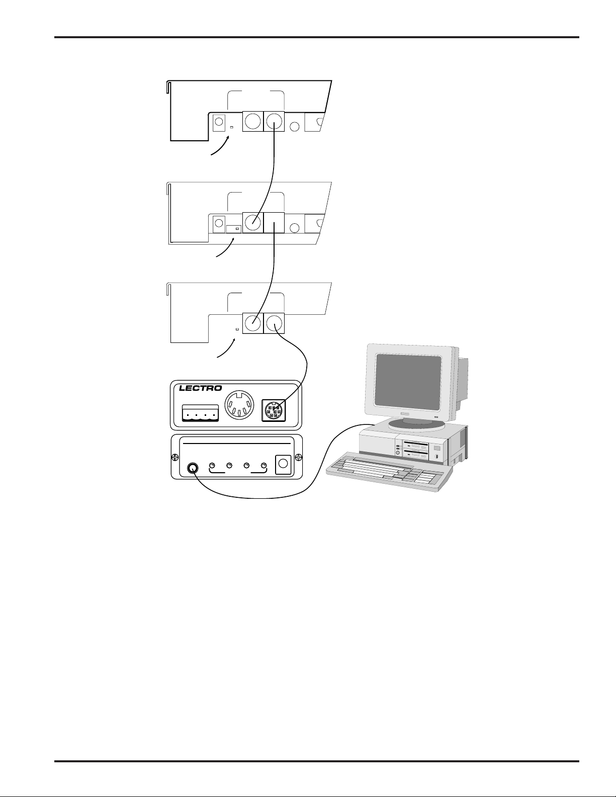
To use the PT3, it must be powered on with the LecNet expansion connector attached to the Expansion In jack of the
last device on your LecNet chain. The AXlink port connector or MIDI jack should be connected as appropriate. The
PT3 need not remain connected to a PC once it has been set up.
OPTIONAL CONNECTIONS
When setting up the PT3, it can be useful to have the LecNet expansion port connected. That way, the PT3 software
can detect the types and addresses of all attached LecNet components, saving you the time it takes to look up and
enter that information. It might also be convenient to have the AXlink or MIDI connection already established so you
can try out new settings quickly.
4
Page 5
PWR
IN
M
A
S
(CH40)
T
E
R
20 VAC
Switch in
MASTER Position
PWR
IN
M
A
S
(CH40)
T
E
R
20 VAC
Switch in
SLAVE Position
PWR
IN
M
A
S
(CH40)
T
E
R
20 VAC
EXPANSION
S
L
A
V
OUT IN
E
EXPANSION
S
L
A
V
OUT IN
E
EXPANSION
S
L
A
V
OUT IN
E
RS232
RS232
RS232
Protocol Translator
AM8
(Master)
AM8
(Slave)
AM8
(Slave)
Switch in
SLAVE Position
GND
AXM
MIDI
AXP
PWR
LecNet
EXPANSION
PT3
Rear
Panel
AXlink PORT
LECTROSONICS PT 3
PC PORT
POWER/
(RS-232)
PC LecNet MIDI AXlink
Note: In AMX installations, it is possible that the PT3’s AXlink device number setting will conflict with another AMX-
PROTOCOL TRANSLATOR
PWR (CH40)
PORT STATUS
PT3 Front Panel
Typical PT3 connection to
LecNet chain and
computer
compatible device until PT3 setup is complete. When in doubt, leave the AXlink port unconnected until you have set
up the PT3.
PT3 CONCEPTS
The PT3 translates messages to and from the LecNet using three basic methods:
Using these three techniques, the PT3 moves information to and from the LecNet simply, easily and flexibly.
actions, monitors
, and
strings
.
ACTIONS
The most basic function the PT3 performs is to issue LecNet commands in response to AXlink or MIDI messages.
Actions
timings. The PT3 translates AXlink or MIDI messages (known as
translations comprises the
are named LecNet commands, which may be used with little regard for the underlying byte sequences or
action map
triggers
, which is nothing more than a list of triggers (AXlink or MIDI messages) and
) into LecNet actions. This collection of
their associated LecNet actions. One trigger may set off an ordered sequence of actions, if desired.
Rio Rancho, NM – USA
5
Page 6

The PT3 software comes with a large list of common LecNet actions for a wide variety of LecNet devices. This list is
stored as a separate disk file (actions.ini) which may be updated from Lectrosonics’s web site as new LecNet
devices are introduced (see ACTION AND MONITOR FILES in the ADVANCED CONCEPTS section for the web
address). The list is also user-extensible, via the user-friendly Actions Master List editor.
MONITORS
In AMX installations, it is sometimes useful for AMX levels and channels to automatically track with changes to a
LecNet device. For example, a touch panel button could be made to darken whenever a particular microphone on an
automatic mixer is in use. The PT3 can monitor LecNet devices for status information, notifying the AMX master
whenever changes occur.
Monitors
or timings. The PT3 can continually issue selected status inquiries (monitors) and relay any changes via an AXlink
level or channel (
simply a list of LecNet monitors and their associated AXlink mappings.
The PT3 software comes with a large list of common LecNet monitors for a wide variety of LecNet devices. This list is
stored as a separate disk file (monitors.ini) which may be updated from Lectrosonics’s web site as new LecNet
devices are introduced (see ACTION AND MONITOR FILES in the ADVANCED CONCEPTS section for the web
address). The list is also user-extensible, via the user-friendly Monitors Master List editor.
STRINGS
In AMX installations, it is sometimes necessary to send exact byte sequences to the LecNet and examine the returned string directly. While actions and monitors make the most common interfacing tasks trivially simple to configure, in some cases they are not sufficient. For example, if an AXCESS program wished to query a specific LecNet
address and receive the string identifying the type of device attached (e.g. “AM8”), it would have to use strings to do it.
Actions fetch no response, and monitors repeat continuously and only return numeric information. Sometimes a
LecNet command is simply too long to be expressed as an action, in which case the strings capability must be used.
PT3 strings are still much easier to use than an RS-232 port. The LecNet address, byte sequence, and reply length
(if any) are sent directly to the PT3 as a single SEND_STRING command. The reply is automatically accumulated in
a buffer, as with any AMX-compatible device. LecNet protocol timings are handled transparently by the PT3.
are named LecNet status inquiries, which may be used with little regard for the underlying byte sequences
AXlink mapping
). These monitors and AXlink mappings comprise the
monitor map
, which is
SETTING UP THE PT3
Preparing the PT3 for use mostly involves using the PT3 software to describe your setup. In AMX installations, some
AXCESS programming is also required, as it is with any AMX-compatible device. Once a configuration has been
described, it should be saved to disk. It can then be transmitted to the PT3, which will start performing the new
translations immediately. PT3 settings persist when the device is powered off.
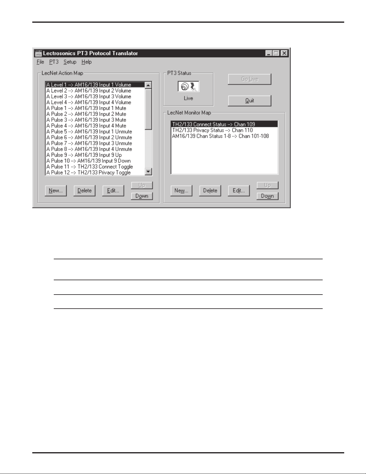
MAIN WINDOW
The main window provides an at-a-glance overview of the PT3 setup currently being edited.
On the left side is the LecNet Action Map frame. (For an explanation of actions and the action map, see the PT3
CONCEPTS section.) A summary of the action map is displayed in the form of a list box. To save space, the first
letter in each action summary is either M for MIDI or A for AXlink. Scroll bars appear if the entire list cannot be
displayed at once. The New button adds, then edits a new entry, Delete removes one, and Edit alters the selected
entry. (The New and Edit buttons bring up the Edit LecNet Action Map Entry window, described later.) The Up and
Down buttons can be used to change the order of items in the list. If multiple actions share the same trigger, the
actions are executed in the order shown in the list, from top to bottom. Otherwise, the order of items in the action
map is unimportant. The action map can hold up to 96 entries. It is valid, but unusual, to have an empty action map.
On the right side is the LecNet Monitor Map frame. (For an explanation of monitors and the monitor map, see the PT3
CONCEPTS section.) The monitor map works similarly to the action map, except that it can hold only 16 entries. The
New and Edit buttons bring up the Edit LecNet Monitor Map Entry window, described later. Up and Down buttons
6
Page 7
Protocol Translator
are provided to help organize the list cosmetically, however the order is not important to the functioning of the PT3. It
is valid, and fairly common, to have an empty monitor map.
The PT3 Status frame displays the current status of the connection between the computer and the PT3. The connection has three states, as explained in the table below.
Not Connected The computer is not currently communicating with the PT3. This is the case whenever the
active window does not belong to the PT3 software, as well as whenever the PT3 is not
connected to the PC.
Ready The PT3 is connected but its settings do not match those shown by the PT3 software. It
will be necessary to save your settings to the PT3 before they take effect.
Live The PT3 is connected and the settings shown are up to date. The PT3 is operating on the
settings shown.
Note: If the active window in the Windows system belongs to an application besides the PT3 software, the PT3
software will pause PT3 operation and disconnect from the serial port until it again has focus. This is intended
to prevent serial port conflicts.
The Go Live button attempts to bring the PT3 into synch with the displayed user settings. Most often it will cause
settings to be saved to the PT3, however if blank settings are displayed, the Go Live button will instead cause the
current settings to be read from the PT3.
The Quit button exits, prompting to save any unsaved changes as appropriate. If a PT3 is connected, a prompt is
issued: “Do you wish to keep the PT3 running?”. This question is necessary because the LecNet can only be controlled by the PT3 or the PC, but not both. If you will need to control other LecNet devices from the PC after quitting
the PT3 program, choose No. Otherwise, choose Yes and allow the PT3 to do its job.
Rio Rancho, NM – USA
7
Page 8
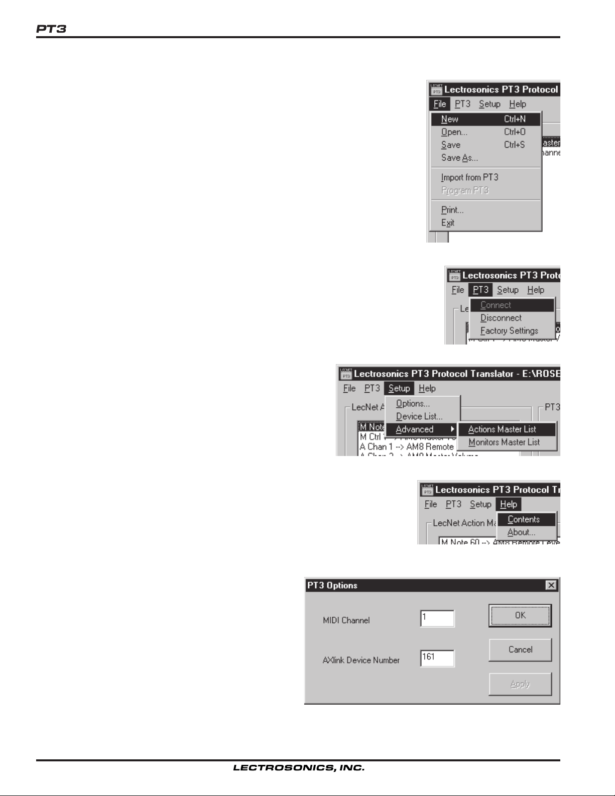
The File menu offers the usual commands, plus two special ones. New prepares the
software for composing new settings by initializing all controls. Open reads settings
in from a previously saved file. Save saves your work in the current file. Save As
saves your work in any file you specify. Filenames are limited to 8 characters in
length. Import from PT3 loads the current settings from an attached PT3. This is
done automatically if a PT3 can be detected when the software is started. Program
PT3 causes the current settings to be written out to an attached PT3. (The Go Live
button is usually a more convenient way to accomplish this function.) Print creates a
hardcopy listing of your settings. Exit does the same as the Quit button.
The PT3 menu lets you explicitly connect and disconnect from an attached PT3, as well
as restore the PT3 to its original factory settings. The Factory Settings command
requires a confirmation before erasing any settings.
The Setup menu provides access to PT3 setup features not
appearing in the main window. Options brings up the Options
window, allowing the AXlink device number and MIDI channel
number to be edited. Device List brings up the Device List
window, which tells the PT3 what LecNet devices are available.
The Advanced submenu provides access to the Actions
Master List and Monitors Master List. These allow users with
special requirements to create their own LecNet actions and
monitors.
The Help menu brings up the help file table of contents and the About box. The
About box shows the revision of the PT3 software. If a PT3 is connected, its
firmware revision is also shown.
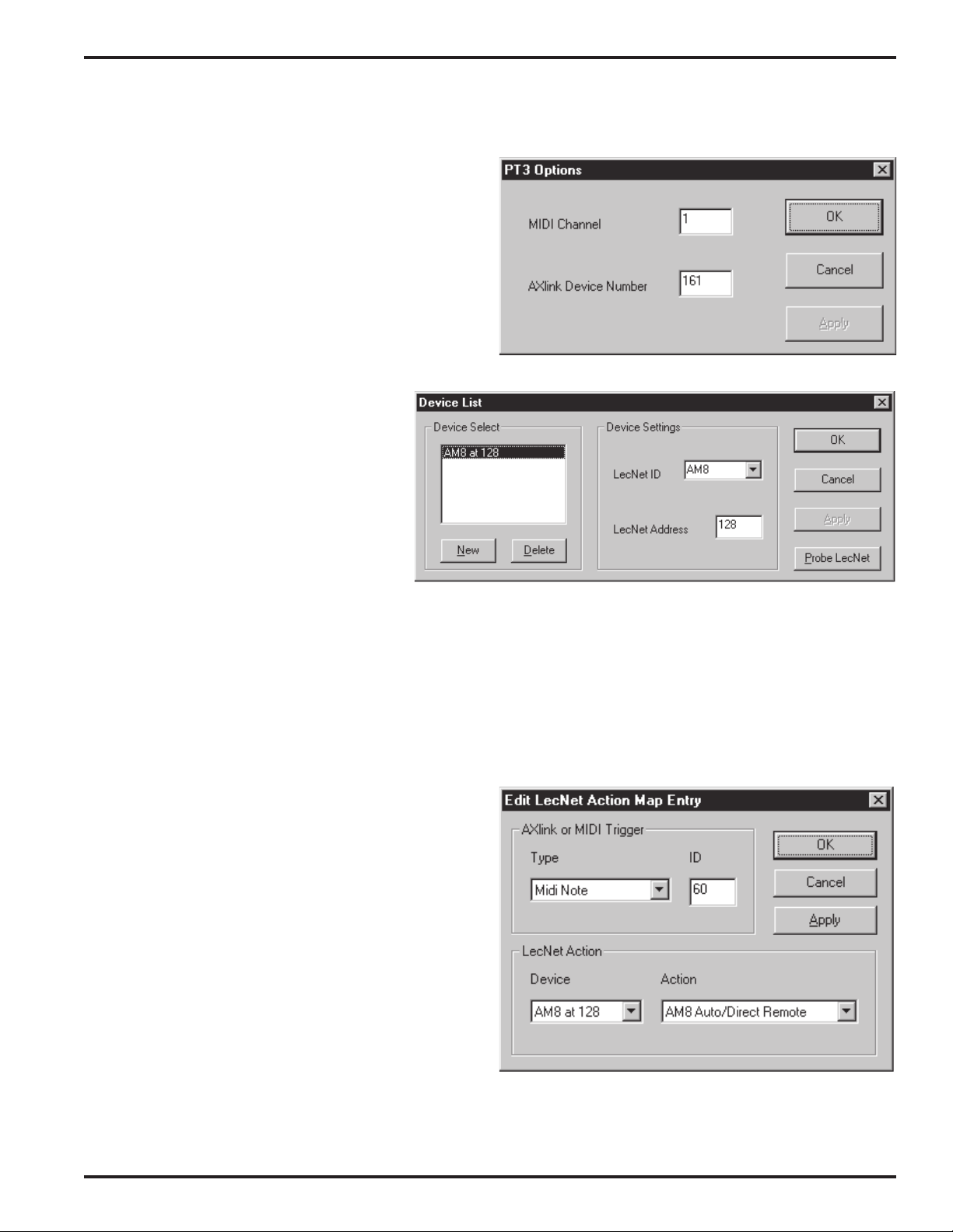
OPTIONS WINDOW
The Options window is used to select the AXlink device
number and the MIDI channel to be used by the PT3.
Valid AXlink device numbers are (decimal) 1 to 255. Valid
MIDI channels are (decimal) 1 to 16. In both cases, it is
sufficient to choose a number that does not conflict with
any other devices connected on the same wire.
If MIDI is not to be used, it doesn’t matter what MIDI
channel is selected. If the AXlink port is not to be used,
the AXlink device number setting is likewise unimportant.
8
Page 9
Protocol Translator
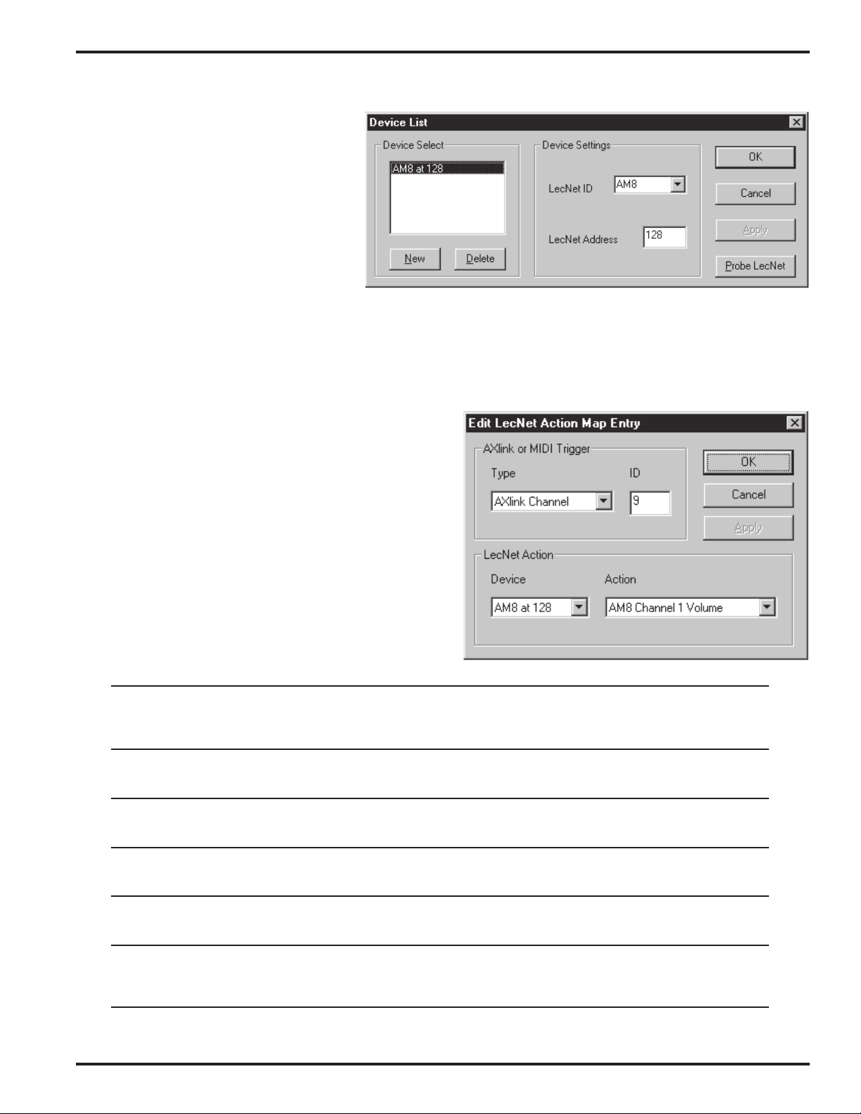
DEVICE LIST WINDOW
The Device List window tells the PT3 what
LecNet devices will be connected. These
settings affect what options will be available
in the other windows, and thus should be
supplied first.
On the left side is the Device Select frame,
showing the device list itself. The New and
Delete buttons may be used to edit the list.
To change a list entry, select it in the list,
then make edits in the Device Settings
frame. LecNet ID must contain the official name of the device (e.g. “AM8”). A pull-down list of common LecNet
devices is provided for convenience. If your device is not in the list, you may type in the name. In order to work
correctly, the name must be spelled the same way in the device list, the actions master list, and the monitors master
list. LecNet Address must contain the address assigned to that LecNet device, in the range (decimal) 128-255.
If you have your LecNet gear connected during PT3 setup, the Probe LecNet button will autodetect the names and
addresses of all connected devices.
EDIT LECNET ACTION MAP ENTRY WINDOW
The Edit LecNet Action Map Entry window describes a
single translation from an AXlink or MIDI trigger message
to a LecNet Action.
Each trigger has a type (what kind of message it is) and a
specific ID number (in base 10).
The LecNet Action portion of the window simply requires
selection of a LecNet device and an action for that device.
If the required device isn’t listed or if no device is listed, use
the Device List window to add devices. If the required
action is not available, you may use the Actions Master List
window to create it.
Midi Controller This is a MIDI controller such as a modwheel or sustain pedal. The ID is the controller number.
The modwheel is controller 1. Consult the MIDI implementation document for your MIDI
transmitter to obtain other controller numbers. The action is executed whenever the
controller's value changes.
Midi Program This is a MIDI program change message. The ID is the program number, from 0 to 127. Note
that on some MIDI equipment, these numbers are not displayed as they are transmitted. The
action is executed whenever the specific program change message is received.
Midi Note This is a MIDI note-on message with nonzero velocity. (The MIDI spec says a note-on mes-
sage with zero velocity counts as a note-off.) The ID is the MIDI note number. Middle C is
note 60. The action is executed whenever the specific note-on message is received
AXlink Channel When the PT3's specified AXlink channel changes (either on or off), the action is executed.
This causes a LecNet feature to switch on and off with the channel value. See also AXlink
Pulse.
AXlink Level When the PT3's specified AXlink level changes, the action is executed. Valid level IDs are 1-8
and 9-64 (see AXLINK DEVICE SPECIFICATION for details on pseudo-levels 9-64). Levels
are useful for continuous adjustments like volume controls.
AXlink Pulse The action is executed only when the AXlink channel changes from off to on. This causes a
LecNet feature to activate whenever the channel is pulsed. See also AXlink Channel. For a
detailed description of pulsed vs. normal use of a channel, see the AXCESS PROGRAMMING
HINTS section.
Rio Rancho, NM – USA
9
Page 10

EDIT LECNET MONITOR MAP ENTRY WINDOW
The Edit LecNet Monitor Map Entry window describes a single
monitor map entry.
At the top is listed the LecNet device and selected monitor. If
the required device isn’t listed or if no device is listed, use the
device list window to add devices. If the required monitor is
not available, you may use the Monitors Master List window to
create it.
At the bottom the AXlink mapping is described. Three types of
mapping are possible.
Channel useful for monitoring single on/off parameters that can change automatically (e.g.
telephone hybrid connect status). Valid channel IDs are 1-255 decimal.
Level useful for monitoring numeric parameters that can change automatically (e.g.
automatic mixer channel level). Valid level IDs are 1-8 and 9-64 decimal (see
AXLINK DEVICE SPECIFICATION for details on pseudo-levels 9-64).
8 Channels useful for monitoring bitwise grouped on/off parameters that can change automati-
cally (e.g. automatic mixer microphone status). The least significant bit is mapped to
the lowest numbered channel. Valid starting channels are 1-248 decimal.
ACTIONS MASTER LIST WINDOW
The Actions Master List window may be used to create new LecNet actions covering functions not anticipated by
Lectrosonics. Using the Actions Master List is not difficult, but you may wish to check Lectrosonics’s web site for
updates, in case the function you need has already been created (see ACTION AND MONITOR FILES in the ADVANCED CONCEPTS section for the web address). If the function you need to perform requires that more than
seven bytes be sent to the device, not including the LecNet address, it cannot be described as an action. AXCESS
programmers can achieve more sophisticated interchange with the SEND_STRING capability. See the AXLINK
DEVICE SPECIFICATION section for details.
10
Page 11
Protocol Translator
On the left side of the window is an editable list of LecNet actions. The New and Delete buttons may be used to
extend or shorten the list. Lectrosonics-supplied actions cannot be deleted or edited, but may be browsed here for
informational purposes. User actions are added to the end of the list.
To the right are the action details. The Device Type is the name identifying the LecNet device. This field is important
as only those actions whose device type matches the selected device will be offered as a choice in the Edit LecNet
Action Map Entry window. The Action Name should be chosen to suggest what the action does. The name should
also connote whether the action has a value (“master volume” suggests a value, “mute channel 1” does not). Action
Length indicates the total number of bytes (in decimal or base 10 notation, not counting the LecNet address) which
must be sent to the device to perform the action. An action may transmit up to 7 bytes after the LecNet address. If
more bytes are required to perform a desired function, the AXCESS language SEND_STRING capability may be
used. See the AXLINK DEVICE SPECIFICATION section for details.
The Value Byte parameter indicates which byte in the LecNet message (if any) is adjustable according to the trigger
value. If a value byte is chosen, its Max. Value (in base 10 or decimal notation) must be supplied. Scaling is performed automatically, and the minimum value is always zero. The Value invert checkbox permits the polarity of the
trigger value to be inverted, so the lowest trigger value causes the largest LecNet value byte to be transmitted. This is
useful for LecNet functions such as the AM8 remote level adjustments, where the value 0 selects the maximum
volume and the value 31 selects the minimum. For more detailed information on value scaling and inversion, please
refer to the ADVANCED CONCEPTS section.
Note: If a PT3 is set up with user-defined actions, and its settings are subsequently imported on a different computer
without the same user-defined actions available, different actions will be shown in the action map. The PT3 will
continue to function as configured until it is explicitly reconfigured. See the ADVANCED CONCEPTS section for
information on sharing user-defined actions between computers.
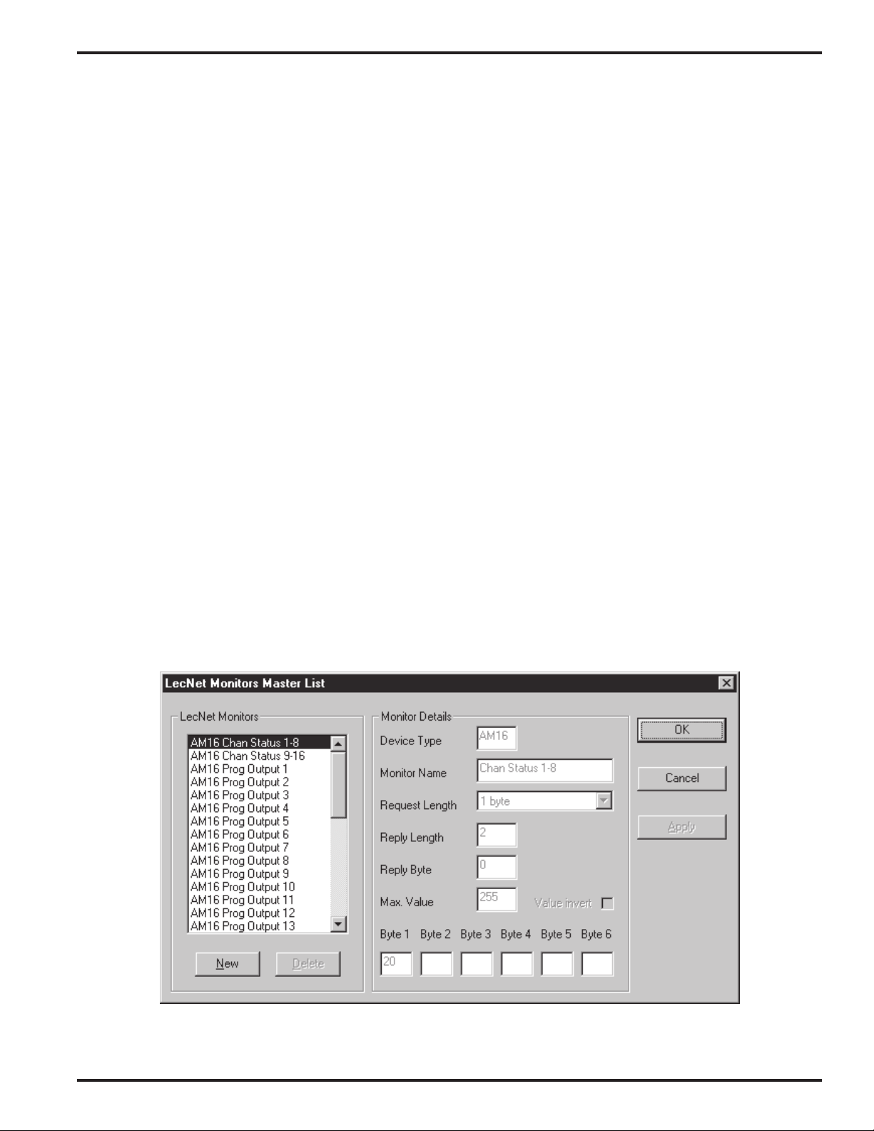
MONITORS MASTER LIST WINDOW
The Monitors Master List window may be used to create new LecNet monitors covering status inquiries not anticipated by Lectrosonics. Using the Monitors Master List is not difficult, but you may wish to check Lectrosonics’s web
site for updates, in case the inquiry you need has already been created (see ACTION AND MONITOR FILES in the
ADVANCED CONCEPTS section for the web address). If the inquiry you need to perform requires that more than
six bytes be sent to the device, not including the LecNet address, or if the returned data is not numeric and
concise, it cannot be described as a monitor. AXCESS programmers can achieve more sophisticated interchange
with the SEND_STRING capability. See the AXLINK DEVICE SPECIFICATION section for details.
Rio Rancho, NM – USA
11
Page 12

On the left side of the window is an editable list of LecNet monitors. The New and Delete buttons may be used to
extend or shorten the list. Lectrosonics-supplied monitors cannot be deleted or edited, but may be browsed here for
informational purposes. User monitors are added to the end of the list.
To the right side are the monitor details. The Device Type is the name the LecNet device uses to identify itself. This
field is important as only those monitors whose device type matches the selected device will be offered as a choice in
the Edit LecNet Monitor Map Entry window. The Monitor Name should be chosen to suggest what is being reported.
The name should also connote whether the returned data is on/off (best mapped to a channel), continuous (best
mapped to a level) or bitwise (best mapped to a bank of 8 channels). Request Length indicates the total number of
bytes (not counting the LecNet address) which must be sent to the device to execute the inquiry. A monitor may
transmit up to 6 bytes after the LecNet address. If more bytes are required to perform a desired inquiry, the AXCESS
language SEND_STRING capability may be used. See the AXLINK DEVICE SPECIFICATION section for details.
The Reply Length parameter tells the PT3 how many bytes are expected in the reply to this inquiry. This must be the
total number, including any ignored bytes at the end of the message, in decimal notation (base 10). Reply Byte is the
offset (in base 10) of the byte that is retrieved and mapped as the current value of this monitor. The first byte in the
reply has offset 0.
The Max. Value parameter causes the reply byte’s value to be numerically scaled. This can have a disastrous effect
on bitwise information, but is useful for convenient bargraph display of “level” type information. The value returned
may be optionally inverted with the Value invert checkbox. This is the remedy for LecNet functions that return the
opposite of what is desired (e.g. attenuation vs. volume). For more detailed information on value scaling and inversion,
please refer to the ADVANCED CONCEPTS section.
Note: If a PT3 is set up with user-defined monitors, and its settings are subsequently imported on a different computer
without the same user-defined monitors available, different monitors will be shown in the action map. The PT3 will
continue to function as configured until it is explicitly reconfigured. See the ADVANCED CONCEPTS section for
information on sharing user-defined monitors between computers.
SETTING UP THE PT3 FOR THE FIRST TIME:
A TUTORIAL FOR MIDI USERS
This section guides you through the setup procedure for an example application. While your needs are certainly
different and more sophisticated, the basic setup process will be the same.
This tutorial may be followed with or without the PT3 connected to your computer, however it is recommended that
you connect your PT3 if possible. Similarly, it is sometimes convenient to have your LecNet devices connected to the
PT3’s expansion connector during the setup process. Refer to INSTALLING THE HARDWARE for information on
connecting the PT3.
In this tutorial, only translations to command a single AM8 mixer at LecNet address 128 are supplied. If you don’t
have an AM8 mixer, or your AM8 mixer has a different LecNet address, you may substitute your information where
applicable, or you may simply follow the steps exactly for instructional purposes.
In order to make it as easy as possible to verify PT3 operation, the settings in this tutorial cause the LED channel
indicators on the front panel of an AM8 mixer to turn on and off. Proper functioning will thus be apparent, without the
need to connect anything to the AM8’s inputs or output. A musical keyboard with MIDI capability is required to
complete the testing portion of the tutorial.
1. Start the PT3 software. If a PT3 is connected, its settings (which may be blank) will be read in at this time. If a PT3
is not connected, an informational dialog appears, stating that no PT3 was detected, but that you may still work offline.
If the software failed to detect a PT3 in spite of the fact that it is connected, refer to the TROUBLESHOOTING section.
Once the Main window appears, select New from the File menu, answering No to any questions about saving previous settings, to ensure a fresh start.
12
Page 13
Protocol Translator
2. From the Setup menu, invoke the Options window. Here, we will tell the PT3 its identity with respect to the MIDI
interface and the AXlink bus.
The default MIDI channel is 1. Channel 1 is probably
acceptable, though you should select a different channel
if you are aware of any conflicts. If you are simply testing
the PT3 with a musical keyboard, you needn’t worry
about conflicts.
The AXlink device number setting has no effect if AMXcompatible equipment is not connected.
Once you are satisfied with the MIDI channel selection,
click OK.
3. From the Setup menu, invoke the Device
List window. This is where we tell the PT3
what LecNet devices are connected. For this
tutorial, it is assumed that a single AM8
mixer will be connected at LecNet address
128. If you don’t plan to connect an AM8
mixer, or if your AM8 uses a different LecNet
address, you may substitute your information
where applicable.
If your LecNet devices are connected now,
you may use the Probe LecNet button to
automatically detect your LecNet gear and
populate the list box. If your LecNet devices are not currently connected, you will need to click New, then enter the
LecNet ID (device type) and address of each LecNet device you wish to use with the PT3. The LecNet ID is simply
the name of the product, such as AM8 or MM8. A device’s LecNet address can be changed at any time with the
LecNet Master Pro software. If you are unsure of the address of any LecNet device, you may use the Probe LecNet
button on the Device List window, or the LecNet Master Pro software, to detect it.
If you are following the tutorial exactly, make your device list window look like the one pictured here, with a single AM8
located at address 128.
When you are finished with the device list, click OK.
4. From the main window’s Action Map frame, click
New... to invoke the Edit LecNet Action Map Entry
window. Change the settings to translate MIDI note 60
(middle C) to the AM8’s Auto/Direct Remote action, as
shown.
Each AM8 input may be configured as either Auto (active
only when signal present) or Direct (always active).
When invoked, the Auto/Direct Remote action will
instruct the AM8 that the Auto vs. Direct status of each
AM8 input shall be selected by LecNet commands, not by
the dipswitches on the rear panel.
If more than one LecNet device appears in the device list,
you will need to select the proper device first, then the
action, as only actions pertaining to the selected device
appear in the action list.
When the Edit LecNet Action Map Entry window is filled
in as shown, click OK. A summary of the new translation should appear in the main window’s action map, as shown
in the figure for step 7.
Rio Rancho, NM – USA
13
Page 14

5. From the main window’s Action Map frame, click
New... again. Change the settings to translate MIDI note
62 (the D above middle C) to the AM8’s Auto/Direct All
Direct action, as shown. When invoked, this action will
instruct the AM8 to set all inputs to Direct mode, lighting
all eight channel status LEDs.
Click OK when done. A summary of the new translation
should appear in the main window’s action map, as
shown in the figure for step 7.
6. From the main window’s Action Map frame, click
New... again. Change the settings to translate MIDI note
64 (the E above middle C) to the AM8’s Auto/Direct All
Auto action, as shown. When invoked, this action will
instruct the AM8 to set all inputs to Auto mode, extinguishing all eight channel status LEDs (provided there is
no input signal).
Click OK when done.
7. Your main window should now
look like this. If your PT3 is not
connected, the PT3 Status frame
will show “Not Connected” instead
of “Ready”.
From the File menu, select Save
to save your settings to a disk file.
You may use any name you wish
(up to 8 characters) and save the
file in any directory that is appropriate.
14
Page 15

Protocol Translator
8. If the PT3 is connected, you may now transfer your new settings to it by clicking the Go Live button. The Power/PC
LED on the PT3 will flicker while the transfer is taking place. It is necessary to perform this step if you wish to test the
PT3 in the following steps.
9. If you do not wish to test your setup, you may skip to step 16. To test the PT3 settings as transferred in step 8,
disconnect the PT3’s PC port cable and power connection. Leaving the PC port cable disconnected, power the PT3
back on. The PC connection is not needed once your settings have been stored to the PT3. Leaving the PC disconnected guarantees that no software component of LecNet Master Pro is capable of disabling the PT3.
10. Be sure the PT3 is connected to the AM8 mixer and your MIDI keyboard (refer to INSTALLING THE HARDWARE for
hookup instructions). All devices should be powered on. Turn all the AM8 volume controls all the way down. This will
ensure that the front panel LED channel indicators will remain off when the channels are in Auto mode.
11. Play a few notes on the MIDI keyboard. The MIDI LED on the PT3 should flicker. If it doesn’t, the PT3 is not receiv-
ing MIDI signals. Check that the MIDI cable is connected to the MIDI OUT jack on the keyboard, and select OMNI mode
on the keyboard, if available. Refer to the TROUBLESHOOTING section if you need help.
12. Once the MIDI LED responds to keyboard activity, press middle C. If you are unsure which C is middle C, try
pressing each C key in turn, watching the LED indicators. The MIDI LED will flicker with every note pressed. The
LecNet indicator will flicker only when a translated note (middle C) is pressed. If none of the C keys cause the LecNet
indicator to flicker, the keyboard’s base MIDI channel is probably different from the PT3’s MIDI channel as selected in
step 2. For additional help, consult the TROUBLESHOOTING section or your keyboard’s MIDI documentation.
13. Strike middle C (note 60). Both the MIDI and LecNet LEDs should flicker, indicating a successful translation. Middle
C (note 60) invokes the Auto/Direct Remote action, preparing the AM8 for remote Auto vs. Direct commands.
14. Strike the D above middle C (note 62). This invokes the Auto/Direct All Direct action, setting all the AM8’s inputs to
Direct mode, thus lighting all the AM8’s front panel LED channel indicators.
15. Now strike the E above middle C (note 64). This invokes the Auto/Direct All Auto action, setting all the AM8’s
inputs to Auto mode, thus extinguishing all the AM8’s front panel LED channel indicators.
16. Congratulations! You are well on your way to mastering a very powerful and sophisticated one-of-a-kind tool, which
makes some previously difficult tasks much easier and previously impossible tasks possible.
SETTING UP THE PT3 FOR THE FIRST TIME:
A TUTORIAL FOR AMX USERS
This section guides you through the setup procedure for an example application. While your needs are certainly
different and more sophisticated, the basic setup process will be the same.
This tutorial may be followed with or without the PT3 connected to your computer, however it is recommended that
you connect your PT3 if possible. Similarly, it is sometimes convenient to have your LecNet devices connected to the
PT3’s expansion connector during the setup process. Refer to INSTALLING THE HARDWARE for information on
connecting the PT3.
To test the PT3 on an AMX system it is necessary to establish serial communication with the AMX master, usually
using the terminal emulator included within AXCESS. The AMX master and touch panel need not be programmed to
follow these simple steps. In case the PT3’s current AXlink device number conflicts with another device on your
AXlink bus, it is recommended that you do not connect the AXlink cable until instructed to do so.
In this tutorial, only translations to command a single AM8 mixer at LecNet address 128 are supplied. If you don’t
have an AM8 mixer, or your AM8 mixer has a different LecNet address, you may substitute your information where
applicable, or you may simply follow the steps exactly for instructional purposes.
In order to make it as easy as possible to verify PT3 operation, the settings in this tutorial cause the LED channel
indicators on the front panel of an AM8 mixer to turn on and off. Proper functioning will thus be apparent, without the
need to connect anything to the AM8’s inputs or output.
Rio Rancho, NM – USA
15
Page 16

1. Start the PT3 software. If a PT3 is connected, its settings (which may be blank) will be read in at this time. If a PT3
is not connected, an informational dialog appears, stating that no PT3 was detected, but that you may still work offline.
If the software failed to detect a PT3 in spite of the fact that it is connected, refer to the TROUBLESHOOTING section.
Once the Main window appears, select New from the File menu, answering No to any questions about saving previous settings, to ensure a fresh start.
2. From the Setup menu, invoke the Options window. Here, we will tell the PT3 its identity with respect to the MIDI
interface and the AXlink bus.
The default AXlink device number is 161. Any number
may be used, provided it is unique on the AXlink bus. To
be sure of selecting a unique number, you may query the
AXlink bus from the AXCESS development system. The
command is SHOW DEVICE from the terminal emulator.
Any device number not listed may be used. In the event
of a conflict, the AMX touch panel will beep persistently.
Refer to the TROUBLESHOOTING section for tips on
diagnosing this condition.
Without a MIDI cable connected, the MIDI setting will
have no effect.
Once you are satisfied with the AXlink device number, click OK.
3. From the Setup menu, invoke the Device
List window. This is where we tell the PT3
what LecNet devices are connected. For this
tutorial, it is assumed that a single AM8 mixer
will be connected at LecNet address 128. If
you don’t plan to connect an AM8 mixer, or if
your AM8 uses a different LecNet address,
you may substitute your information where
applicable.
If your LecNet devices are connected now,
you may use the Probe LecNet button to
automatically detect your LecNet gear and populate the list box. If your LecNet devices are not currently connected,
you will need to click New, then enter the LecNet ID (device type) and address of each LecNet device you wish to use
with the PT3. The LecNet ID is simply the name of the product, such as AM8 or MM8. A device’s LecNet address
can be changed at any time with the LecNet Master Pro software. If you are unsure of the address of any LecNet
device, you may use the Probe LecNet button on the Device List window, or the LecNet Master Pro software, to
detect it.
If you are following the tutorial exactly, make your device list window look like the one pictured here, with a single AM8
located at address 128.
When you are finished with the device list, click OK.
4. From the main window’s Action Map frame, click
New... to invoke the Edit LecNet Action Map Entry
window. Change the settings to translate a pulse on
AXlink channel 1 to the AM8’s Auto/Direct Remote
action, as shown.
A pulse on an AXlink channel causes the channel to turn
on briefly, then off again. For a detailed explanation of
pulsed vs. normal use of a channel, refer to the AXCESS
PROGRAMMING HINTS section.
Each AM8 input may be configured as either Auto (active
only when signal present) or Direct (always active).
When invoked, the Auto/Direct Remote action will
16
Page 17

Protocol Translator
instruct the AM8 that the Auto vs. Direct status of each AM8 input shall be selected by LecNet commands, not by the
dipswitches on the rear panel.
If more than one LecNet device appears in the device list, you will need to select the proper device first, then the
action, as only actions pertaining to the selected device appear in the action list.
When the Edit LecNet Action Map Entry window is filled in as shown, click OK. A summary of the new translation
should appear in the main window’s action map, as shown in the figure for step 9.
5. From the main window’s Action Map frame, click New...
again. Change the settings to translate a pulse on AXlink
channel 2 to the AM8’s Auto/Direct Local action, as
shown. When invoked, this action will instruct the AM8
that the Auto vs. Direct status of each AM8 input shall be
selected by the dipswitches on the rear panel, not by
LecNet commands. This action does the opposite of the
action described in step 4.
When the Edit LecNet Action Map Entry window is filled in
as shown, click OK. A summary of the new translation
should appear in the main window’s action map, as shown
in the figure for step 9.
6. From the main window’s Action Map frame, click New...
again. Change the settings to translate a pulse on AXlink
channel 3 to the AM8’s Auto/Direct All Direct action, as
shown. When invoked, this action will instruct the AM8 to
set all inputs to Direct mode, lighting all eight channel
status LEDs.
When the Edit LecNet Action Map Entry window is filled in
as shown, click OK. A summary of the new translation
should appear in the main window’s action map, as shown
in the figure for step 9.
7. From the main window’s Action Map frame, click New...
again. Change the settings to translate a pulse on AXlink
channel 4 to the AM8’s Auto/Direct All Auto action, as
shown. When invoked, this action will instruct the AM8 to
set all inputs to Auto mode, extinguishing all eight channel
status LEDs (provided there is no input signal). This action
does the opposite of the action described in step 6.
When the Edit LecNet Action Map Entry window is filled in
as shown, click OK. A summary of the new translation
should appear in the main window’s action map, as shown
in the figure for step 9.
Rio Rancho, NM – USA
17
Page 18

8. From the main window’s Monitor Map frame, click
New... to invoke the Edit LecNet Monitor Map Entry window.
Change the settings to monitor the AM8’s Chan Status 1-
8, mapping to 8 AXlink channels, starting with channel 101,
as shown. When active, this monitor will cause AXlink
channels 101-108 to turn on and off automatically, tracking
the AM8’s current channel status.
When the Edit LecNet Monitor Map Entry window is filled in
as shown, click OK.
9. Your main window should now
look like this. If your PT3 is not
connected, the PT3 Status
frame will show “Not Connected”
instead of “Ready”.
From the File menu, select
Save to save your settings to a
disk file. You may use any name
you wish (up to 8 characters)
and save the file in any directory
that is appropriate.
10. If the PT3 is connected, you
may now transfer your new
settings to it by clicking the Go
Live button. The Power/PC LED
on the PT3 will flicker while the
programming is taking place. It
is necessary to perform this
step if you wish to test the PT3
in the following steps.
11. If you do not wish to test your setup, you may skip to step 20. To test the PT3 settings as transferred in step 10,
disconnect the PT3’s PC port cable and power connection. Leaving the PC port cable disconnected, power the PT3
back on. The PC connection is not needed once your settings have been stored to the PT3. Leaving the PC disconnected guarantees that no software component of LecNet Master Pro is capable of disabling the PT3.
12. Be sure the PT3 is connected to the AM8 mixer and your AXlink bus (refer to INSTALLING THE HARDWARE for
hookup instructions). All devices should be powered on. Turn all the AM8 volume controls all the way down. This will
ensure that the front panel LED channel indicators will remain off when the channels are in Auto mode.
13. Observe the LED indicators on the PT3. The AXlink port status LED should flash at a steady rate, on for approximately one second, then off for approximately one second. If it does not, check to be sure your AMX master is
operational and the cabling is connected correctly. (Refer to the TROUBLESHOOTING section if you are unable to
obtain AXlink response.) A LecNet monitor is active (from step 8), so you should see periodic activity on the LecNet
LED. If the LecNet LED flashes several times a second, all is well. If it flashes once a second, the PT3 cannot
communicate with the AM8 mixer. Check that the LecNet address of the mixer is correct and that the LecNet expansion cable is installed properly.
14. Start the AXCESS language and enter the terminal emulator, to type directly to the AMX master. Verify that the
master is responding by typing a question mark, then the Enter key. A list of available commands should be displayed. If it is not, check your COM port settings and serial connections to the AMX master, then try again. Enter the
18
Page 19

Protocol Translator
command ECHO ON so you can see what you’re typing. Then enter SHOW DEVICE to see the list of connected
devices. The Lectrosonics Translator should appear in the list. On older masters, it may appear as an unknown device
type, recognizable as the PT3 from its AXlink device number. The PT3 will work properly even if it is identified only as
an unknown device by the AMX master. The important thing is that the master must detect the device with the device
number selected in step 2.
15. To test the actions, enter the command
PULSE [
where
the Auto/Direct Remote action. The AM8 is now prepared to accept Auto vs. Direct channel settings from the
LecNet.
16. Now enter
again substituting the AXlink device number for
action. This sets all AM8 channels to direct mode, causing all 8 front panel LED channel status indicators to illuminate.
17. Next, type in
again substituting the AXlink device number for
action. This sets all AM8 channels to auto mode, extinguishing all 8 front panel LED channel status indicators.
18. To test the monitoring capability, first enter
where
Local action. The AM8 again accepts Auto vs. Direct channel settings from the rear panel dipswitches, rather than
via LecNet commands.
19. Now enter
N
is the AXlink device number selected in step 2 (e.g. PULSE [161,1]). This pulses channel 1, thus performing
PULSE [
PULSE [
PULSE [
N
is the AXlink device number selected in step 2. This pulses channel 2, thus performing the Auto/Direct
N
,1]
N
,3]
N
. This pulses channel 3, thus performing the Auto/Direct All Direct
N
,4]
N
. This pulses channel 4, thus performing the Auto/Direct All Auto
N
,2]
DEVICE STATUS
where N is the AXlink device number selected in step 2. The list of channels which are on from 101 through 108
should correspond with the LEDs on the front of the AM8 mixer. From here, each time you press the Enter key, the
AMX master will repeat the last command, allowing you to continually monitor the status of those channels. Using the
AM8 rear panel dipswitches, try switching some AM8 inputs between auto and direct mode. The status of AXlink
channels 101-108 as reported by the AMX master should track with the LEDs on the front of the AM8.
If any of the above doesn’t work correctly, please refer to the TROUBLESHOOTING section.
20. Congratulations! You are well on your way to mastering a very powerful and sophisticated one-of-a-kind tool,
which makes some previously difficult tasks much easier and previously impossible tasks possible.
N
AXCESS PROGRAMMING HINTS
The topic of programming AMX control systems is a broad one which is well beyond the scope of this manual. There
are nonetheless a few hints we would like to offer. Working examples featuring all of these practices are included on
the distribution disk that comes with the PT3.
PULSED VS. LATCHING CHANNELS
Commonly a channel will be “pulsed” to perform a single task. A good example would be the use of separate buttons
on a touch panel, one to “mute” a mixer input, the other to “unmute” it. When the button is pressed, the PT3 will see
Rio Rancho, NM – USA
19
Page 20

the channel turn on briefly, then switch off again. Such a channel should use the AXlink Pulse mapping, so that the
action happens only once when the channel switches from off to on, and not again when the channel switches from
on to off.
Sometimes it is desirable to have a channel remain on for as long as some state is active. A good example would be
the use of a single button to toggle between muted and unmuted status. In this case, the button should be defined in
the AXCESS program as a latching button, by including it in the DEFINE_LATCHING section. The button is then
mapped as a straightforward channel mapping. The channel turning on invokes the action with its maximum value,
and the channel turning off invokes the action with the value zero. A volume action could thus be mapped to a
channel and used as a mute/unmute function. For more detailed information on values and how they relate to actions,
please refer to the ADVANCED CONCEPTS section.
DETECTING AXLINK DEVICES
The AMX master and connected AXlink-compatible devices all power up at different rates. It is also possible for a
transient problem to briefly take one or more devices offline. Rather than use clumsy delays, AMX Corp. recommends
robust programming techniques so your AXCESS program will work correctly no matter what devices are connected
or not connected. Do not place device initialization in the DEFINE_STARTUP section as it might be executed before
the device is ready to act on it.
The recommended practice is to use variables to keep track of whether or not each device is online, then use the
DEVICE_ID function in the mainline to update the status of each. Using IF statements in the mainline, you can then
ensure that each device is initialized properly when it comes online, and that your application will not start if a required
device is not ready.
INITIALIZING AXLINK LEVELS
Setting an AXlink level in software will normally cause the level change to propagate to the PT3 as programmed.
However, the AMX system is intelligent about level changes, and if it determines that the level is merely being reset to
its present setting, no external AXlink message is generated, and the PT3 will not be notified. To ensure that a level
change will be transmitted in all cases, AMX Corp. recommends setting the level to a value one off from the desired
value, then to the desired value. Since connected levels track together at all times that the devices involved are
online, this technique need only be used during device initialization.
AVOIDING FEEDBACK LOOPS
If a single LecNet parameter is being simultaneously manipulated from more than one control, the temptation may
arise to use a monitor to keep the controls synchronized. This practice is best avoided, as time delays in the system
and disparity between certain LecNet “set” and “get” commands frequently yield loops in which the user must “fight” to
set the control satisfactorily.
Where practical, Lectrosonics recommends that you keep track of device status in your AXCESS program and
monitor only those settings which can change independently of your code. In situations where simultaneous control
and monitoring must be accomplished, Lectrosonics recommends using separate controls to set and read the parameter. For the common case of a volume control and associated mute button, the simple approach of programming the
mute button to force the volume to 0 offers reliable operation and good performance without the need for a monitor.
ADVANCED CONCEPTS
This section treats some of the more subtle aspects of the PT3 in depth, and suggests a few shortcuts for frequent
use.
MULTIPLE ACTIONS FROM A SINGLE TRIGGER
To associate multiple actions with a single trigger, create an action map entry for each action, and assign the same
trigger type and trigger ID to each. When that trigger event occurs, all the associated actions will be executed in the
order in which they occur in the action map. You may use the Up and Down buttons to reorder the entries. Actions
sharing a common trigger need not be listed together in the action map in order to work together, however listing them
together is recommended.
20
Page 21

Protocol Translator
Note: For reliable operation, groups of 16 or more actions sharing a common trigger should be broken into groups of
15 or fewer actions, each with a separate trigger.
INITIALIZING LECNET DEVICES
Some LecNet devices require initialization before the normal action mappings will function. A good example of this is
the Remote Levels On function of the AM8 mixer. This action must be sent once before any mute, unmute and
volume settings will work. Lectrosonics recommends assigning a single pulsed AXlink channel or a single MIDI note
or program change as the trigger for all once-only initialization of LecNet devices. That way a single AXlink or MIDI
command can accomplish the entire LecNet initialization. (See “Multiple Actions from a Single Trigger”, above, if your
initialization includes more than 15 actions.)
FASTER SETUP
For setups requiring a great many translations, you may find it helpful to keep the Edit LecNet Action Map Entry
window displayed continuously during data entry. Clicking Apply will commit your changes to the current entry
without dismissing the window. You can click New in the LecNet Action Map frame one or more times to create new
translation entries. Each new entry has the same contents as the entry that was previously selected, except that the
ID is automatically incremented. This is ideal for creating long sequences of similar translations. The same technique
may be used when creating new monitor map entries.
Other time-savers include double-clicking an action map entry to edit it, and pressing F1 for context-sensitive help
almost any time.
ACTION AND MONITOR FILES
The actions and monitors shown in the Actions Master List and Monitors Master List are stored in ordinary text files.
Lectrosonics-supplied actions and monitors are stored in actions.ini and monitors.ini respectively. These files may
be downloaded from Lectrosonics’s web site and replaced at any time, to make the most recent and most extensive
set of actions and monitors available. The most recent files may be downloaded from http://
www.lectrosonics.com/dl/downsoft.htm
User-supplied actions and monitors are stored in actuser.ini and monuser.ini, in the same text format. If you use
your own actions and monitors, you will want to copy your actuser.ini and monuser.ini files to any computers used to
set up or examine the PT3. If you wish to change the order in which your user-defined actions or monitors are
presented by the PT3 software, the lines in actuser.ini and monuser.ini may be reordered with an ordinary text
editor (e.g. notepad). A sequence number at the beginning of each line enables the PT3 software to locate the proper
actions and monitors regardless of their order in the text files.
HOW VALUES WORK
The PT3 has the ability to scale numerical data in such a way that an action or monitor can be designed to “do the
right thing” regardless of what the underlying LecNet device actually requires. A good example of this is the volume
settings on the AM8 mixer. A setting of 0 selects full volume, and larger numbers select greater and greater amounts
of attenuation. A value of 31 selects the minimum volume (muted). By building the maximum value of 31 and inversion requirement into the action, a standard full-scale (0 to 255) volume control can be created. It is hoped that the
user can regard such actions as “magic” and get the desired results by merely using them intuitively. A complete
explanation is included here for users wanting to fully understand PT3 operation, and users desiring to create new
actions and monitors.
Every trigger event has associated with it a numerical value. Once received, this value is “normalized” to the range of
0 to 255. Here is a list of trigger types and how they are normalized.
Trigger Type Value Received How Normalized
MIDI controller 0-127 mult. by 2 (0-254)
MIDI program none value of 255 used
MIDI note 1-127 (velocity) mult. by 2 (2-254)
AXlink channel off or on 0 or 255
AXlink level 0-255 left alone
AXlink pulse none value of 255 used
Rio Rancho, NM – USA
21
Page 22

This normalized trigger value is inverted (one’s complement: all bits complemented) if the action’s Value invert
checkbox calls for it, then scaled to range from 0 to the action’s Max. Value parameter. The resulting number is
plugged in to the action’s Value Byte and transmitted with the rest of the action. Due to the fact that LecNet com-
mands cannot contain bytes larger than 127, Max. Value is never larger than 127, and some adjustment to the
normalized trigger value is always performed.
Owing to this normalization process, a volume control action can work equally well with an AXlink level or continuous
MIDI controller (fine control), or an AXlink channel or MIDI on/off controller (hard on or off only). In fact, a volume
action used with an AXlink channel is essentially a backwards mute button.
Here is an example, for clarity. Let us assume that AXlink level 1 is mapped to the AM8 Master Volume action in the
action map. An AXlink SEND_LEVEL command sets level 1 to 63, one fourth of the maximum setting. AXlink levels
range from 0 to 255, so the number 63 is already normalized, however this action calls for inversion. The one’s
complement of 63 is 192 (to see why, convert to binary: all bits are complemented). The value 192, from the range of
0 to 255, is now scaled to fit the range of 0 to 31, as the action requires. This yields the final value of 24, which is sent
to the AM8 along with the rest of the action bytes. Note that the value 24 is one fourth of the way from 31 to 0, which
is precisely the desired result.
The scaling and inversion options on monitors work essentially the same way, in reverse. If the value being monitored
represents a level or amount of something, the type of information that might plausibly be displayed as a bar graph on
an AMX touch panel, the scaling capability is provided to save on coding.
Each LecNet monitor retrieves a single value byte from the response string. LecNet response bytes are not limited to
the range of 0-127 as LecNet command bytes are, so this value can be anything from 0 to 255. If this byte contains
simple on/off or bitwise information, it should not be scaled. The Max. Value parameter in this case should be 255. It
still may be desirable to invert the bits, depending on the purpose of the monitor. For values representing continuous
levels, it is customary and usually desirable to normalize that value to the range of 0 to 255.
The translation occurs as follows: the LecNet monitor inquiry is performed and the value byte extracted from the
response. The value byte is inverted (one’s complement) if required. It is then scaled from its original range of 0 to
255 to the range dictated by the monitor’s Max. Value parameter (255 for no scaling). The result is then sent to the
AXlink master according to the mapping method. Here is a list of AXlink mappings and how values are transmitted.
AXlink Mapping How sent
Channel zero: off, nonzero: on
Level as is
8 Channels one bit per channel
Similarly to actions, therefore, continuous and on/off type signals may be interchanged and thanks to the scaling and
inversion will “do the right thing”.
For clarity, here is an example. Let us assume that an AM8’s Comp/Lev Atten (compressor/leveler attenuation) is
mapped to AXlink level 1, for use as a bargraph display. (Note that such a display is likely to appear somewhat
choppy as it will be updated at most a few times a second.) The LecNet inquiry yields a response of 10, one sixth of
the maximum value of 60 available from this function. The monitor does not require that the value be inverted but
does scale it from the range of 0 to 255 to the range of 0 to 60. The scaled value is 41, one sixth of the way from 0 to
255. Thus, the bargraph button associated with level 1 shows the correct proportion at all times, with no AXCESS
coding required besides CONNECT_LEVEL and CREATE_LEVEL.
22
Page 23

Protocol Translator
TROUBLESHOOTING
The following are just general guidelines and initial suggestions. If a problem persists, please refer to the section,
SERVICE AND REPAIR.
No MIDI
communication
No AXlink
communication
No LecNet actions
AMX touch panel beeps
incessantly
MIDI translation
intermittent
Connect a known-good MIDI cable from the MIDI output jack of a musical keyboard to the PT3.
Set the keyboard to OMNI mode and be sure the base MIDI channel matches the MIDI channel
programmed into the PT3. If necessary, reprogram the PT3 with the base MIDI channel used by
the keyboard. Notes on the keyboard should cause the MIDI LED to flicker. Translated MIDI
messages should also cause the LecNet LED to flicker. If the LecNet LED glows steadily in
between notes and no translations are performed, see the last troubleshooting entry in the list.
Be sure AMX master is operational and cable is connected and correctly wired.The AXlink port
status LED should flash on and off slowly. Translated AXlink messages should cause the LecNet
LED to flicker. The PT3 should be detected, at least as an unknown device with the correct AXlink
device number, by the AMX master. From the AXCESS terminal emulator, the SHOW DEVICE
command may be used to verify this. If the LecNet LED glows steadily in between AXlink messages and no translations are performed, see the last troubleshooting entry in the list.
If the LecNet LED glows steadily in between incoming MIDI or AXlink messages, please refer to
the last troubleshooting entry in the list. While rapidly issuing a translated MIDI or AXlink message, observe the LecNet LED. If it flashes rapidly in synch with your actions, a LecNet action is
being taken, but perhaps it isn't having the desired effect. Check your actions to make sure they
do what you want. Be sure you are addressing the correct LecNet device. Note that AM8 and
AM16 volume changes won't work until the Remote Levels On action is performed once. If the
LecNet LED flashes no faster than once a second, despite more rapid sending of translated
incoming messages, the LecNet device is either not connected or set to the wrong LecNet
address. The PT3's LecNet interface is timing out.
Try disconnecting the PT3. If this stops the beeping, then very likely there is an AXlink device
number conflict. Reprogram the PT3 after selecting a new AXlink device number in the Options
window. To find an available device number, start the AXCESS language, invoke the terminal
emulator, then type SHOW DEVICE. Any number not appearing in the list may be used.
The MIDI standard permits incomplete messages to be sent for maximum efficiency. This is valid
and will never be problematic if both the sender and receiver are always connected. If the MIDI
source (e.g. keyboard) has sent some messages before the PT3 was connected, it may be
necessary to issue a program change, note or controller change to force resynchronization. For a
more detailed explanation, see MIDI DEVICE SPECIFICATIONS.
AXlink channels work,
levels do not
AXlink translation intermittent when MIDI also used
Monitored values
updated too infrequently
PT3 software connects
and disconnects
sporadically
PC cannot program PT3
LecNet LED glows
steadily, actions not
performed
The PT3 might be set to a bank other than 0. See AXLINK DEVICE SPECIFICATIONS for an
explanation of the ‘BANK0’ through ‘BANK7’ commands. The AMX master might not have the
levels properly connected. Refer to the included sample AXCESS code for the proper use of
CONNECT_LEVEL.
The PT3 was not designed to perform AXlink and MIDI translations at the same time. Both are
high-speed protocols which require the PT3's full attention.
Owing to the underlying protocols and communication speeds, as much as a two second latency
may be experienced when many monitors are active simultaneously. With fewer monitors active,
much crisper response is obtained. Action and string response times are not significantly affected
by the number of active monitors.
The various components of LecNet Master Pro must share not only the serial port connecting to
the LecNet, but the control of the LecNet devices themselves. When the PT3 software does not
occupy the active window, it suspends operation of the PT3, then releases the serial port. While
this behavior can be confusing, it was designed to allow the user to switch as freely as possible
among various LecNet control panel programs.
Be sure the PC's COM port is not used by any other device and the cable is connected to the PT3.
LecNet Master Pro should be able to detect the PT3 at LecNet address 255.
When the LecNet LED glows steadily, the PT3 is in standby mode. This mode is selected by
LecNet software when LecNet devices besides the PT3 must be accessed or controlled. The PT3
should return to normal operating mode when the PT3 software occupies the active window on
your computer. The PT3 may be forced into normal operating mode by unplugging the PC cable
and powering the PT3 off and on again.
Rio Rancho, NM – USA
23
Page 24

SERIAL CABLE WIRING DIAGRAM
The serial port on the LecNet device is a minimal RS-232 implementation. The figure shows the wiring diagram to
accommodate interconnection with either a 9 or a 25 pin serial port on a PC or other serial device.
LecNet Device to PC
S
R
T
Tip
Ring
Sleeve
3.5MM
Stereo Plug
Wiring Diagram, 9 Pin D-Sub
LecNet Device Transmit
LecNet Device Receive
Gnd
LecNet Port
9 or 25 Pin Female
D-Subminiature
CD
N/C
RX
TX
DTR
Gnd
DSR
RTS
CTS
N/C
RI
1
2
3
4
5
6
7
8
9
Host
Serial
Port
(PC)
Tip
Ring
Sleeve
Wiring Diagram, 25 Pin D-Sub
LecNet Device Transmit
LecNet Device Receive
Gnd
LecNet Port
RX
TX
Sig Gnd
Chassis Gnd
RTS
CTS
DSR
DTR
3
2
7
1
4
5
6
20
Host
Serial
Port
(PC)
24
Page 25

Protocol Translator
SERIAL PORT COMMANDS AVAILABLE
All LecNet devices use a modification of the typical one-to-one connection between two RS-232 compatible devices.
LecNet devices have both an RS-232 transmitter and receiver section. The transmitter section is “tri-stated”, or placed
in a high impedance mode, until the particular device is addressed. To facilitate the simple parallel connection of
multiple devices on a single RS-232 port, an addressing scheme is employed to route commands from the host to the
proper LecNet device. When a device receives its address from the host computer, it temporarily turns on its RS-232
transmitter long enough to send whatever data is requested by the host. In this way, multiple devices may drive a
single transmit signal back to the host, because only the addressed device will turn on its transmitter.
Valid address values are 128-254 (80 hex-FE hex). The PT3 is a special case and always occupies address 255 (FF
hex). Because a LecNet device will interpret any single data byte whose value is greater than 127 as an address, single
byte data (as opposed to addresses) sent from the host must be in the range of 0-127. If a data value needs to be sent
from the host that exceeds 127, the host must format two bytes of output such that the first byte is the lower 7 bits of the
8 bit value, and the second byte is 1 if the MSB of the data byte is 1, or 0 if the MSB of the data byte is 0.
All interchange of commands and data with any LecNet device should be done in hex rather than ASCII. The only
exception to this is the return data on the Get Device Name command (see command description below). Each
LecNet command must be preceded by the address of the device to be controlled. If a device with the requested
address exists on the system, it will respond by sending a 0 (0 hex, not ASCII) back to the host. Thus, each interchange with a LecNet device follows this pattern:
1) Host sends device address in hex (1 byte);
2) Host receives byte of 0 hex from the LecNet device as acknowledgment;
3) Host sends command (1 byte, hex) to the LecNet device;
4) Host and LecNet device exchange data based on particular command sent.
Note that some LecNet commands cause LecNet devices to return an additional acknowledgment byte of data to
confirm the end of a transaction. This is most typical of commands that cause the LecNet device to be busy for more
than a few milliseconds processing the command. The additional acknowledgment byte lets the host know that the
LecNet device is no longer busy and can receive more commands. If a command does return an additional acknowledgment byte, this will be explicitly stated in the command description.
As an example of a specific interchange between a host and a PT3 the following general procedure would be used to
get a name string back from the PT3:
Set up the communications parameters of the device which will be the host. The correct parameters for all LecNet
devices are 9600 baud, no parity, 8 data bits, 1 stop bit. This need only be done once when the host is initialized.
1) Host sends device address 255 (1 byte).
2) Host receives byte of 0 hex from the PT3 as acknowledgment;
3) Host sends command 1 hex (1 byte) to the PT3 to get the name data;
4) The PT3 sends to the host 4 bytes. The first byte is 3 hex, which is the number of bytes in the PT3’s name string.
The PT3 will then send the ASCII characters “P”, “T”, and “3” to the host.
The following section is a listing of available PT3 commands. The word “Host” in the command descriptions means the
IBM PC or compatible, AMX controller, or Crestron controller to which the PT3 is connected.
Rio Rancho, NM – USA
25
Page 26

GENERAL DEVICE COMMANDS
Get Device Name - Causes the PT3 to send its “name” string back. The first data byte is the length of the name
string, and the rest of the data bytes are the device name.
Host sends command - 1
Host receives data bytes: Byte 1 is the length of the name string (3 for the PT3), bytes 2 thru 4 are the ASCII values
for “PT3”.
Get Firmware Version - Causes the PT3 to send to the host the version number of the current firmware (times ten).
For example, Version 1.0 software would be returned as 10 (decimal).
Host sends command - 25
Host receives data byte: firmware version.
Link/Unlink LecNet - Causes the PT3 to connect the PC port through to the LecNet and pause operation, or to
disconnect the PC port from the LecNet and resume operation. This allows the device connected to the PC port to
send commands to other devices connected to the LecNet via the PT3.
Host sends command - 40
Host sends byte - 1 for link, 0 for unlink
Host receives confirmation byte: always 0
Check Link/Unlink Status - Causes the PT3 to indicate whether the PC port is currently linked to the LecNet (and
normal PT3 operation paused) or the PC port is not linked to the LecNet (and the PT3 is operating normally).
Host sends command - 41
Host receives data byte: 1 for linked, 0 for not linked
Set AXlink Device Number - Changes the PT3’s AXlink device number setting to the value specified.
Host sends command - 49
Host sends byte - the desired AXlink device number
Host receives confirmation byte: always 0
Get AXlink Device Number - Retrieves the PT3’s AXlink device number setting.
Host sends command - 50
Host receives data byte: the AXlink device number
SPECIFICATIONS
AXP
AXM
GND
AXlink connector pinout
AXLINK DEVICE SPECIFICATIONS
The PT3 connects to the AXlink bus and responds as a standard AXlink-compatible peripheral. The device number is
software configurable in the Options window, and the device id is fixed at hexadecimal 10, the device id assigned by
AMX Corp. for use by Lectrosonics. The PT3 can translate changes to all 255 channels and all 8 levels normally
associated with an AXlink-compatible device. An additional 56 levels may be simulated (see ‘BANK0’ through
‘BANK7’ on the next page). Direct interaction with the LecNet may be achieved with SEND_STRING.
PWR
26
Page 27

SEND_COMMAND commands
Protocol Translator
The ‘BANK0’ through ‘BANK7’ commands cause changes to levels 1-8 to be treated as different levels by the PT3,
thus simulating 56 additional levels, as shown in the table below. Commonly these commands are sent at the same
time a new touch panel page is displayed, to change the level assignments according to context. The bank setting
affects the levels used for both actions and monitors.
‘BANK0’ Levels 1-8 translate to levels 1-8
‘BANK1’ Levels 1-8 translate to levels 9-16
‘BANK2’ Levels 1-8 translate to levels 17-4
‘BANK3’ Levels 1-8 translate to levels 25-32
‘BANK4’ Levels 1-8 translate to levels 33-40
‘BANK5’ Levels 1-8 translate to levels 41-48
‘BANK6’ Levels 1-8 translate to levels 49-56
‘BANK7’ Levels 1-8 translate to levels 57-64
SEND_STRING capability
The SEND_STRING command may be used to interact directly with LecNet devices. With CREATE_BUFFER,
responses may be received via the LecNet. The basic syntax is as follows:
SEND_STRING
PT3_AXLINK_ID
is the AXlink device number assigned to the PT3 in the Options window. The first byte of the
PT3_AXLINK_ID,string
string
is the LecNet address of the target device. The last byte is 128 greater than the length of the response string (128 for
no response string). The remaining bytes are transmitted to the LecNet device unaltered. Owing to the nature of the
LecNet protocol, these remaining bytes are limited to the range of 0 to 127 decimal.
Here is an example command which will mute channel 1 on an AM8 mixer at LecNet address 128.
SEND_STRING
The first byte is the LecNet address of the AM8, 128. The next three bytes form the Channel 1 Mute command, 6, 0,
PT3_AXLINK_ID
,“128,6,0,31,128”
31. The final 128 indicates that no reply is expected. (The last byte is always 128 greater than the length of the
reply.) Note that such a simple command would more easily be handled as an action, and in fact an action is supplied
to do this.
Here is an example of something which cannot be handled as an Action: a string is sent which queries the device at
LecNet address 128 in order to ensure that it is an AM8, as expected.
SEND_STRING
PT3_AXLINK_ID
,“128,1,132”
The first byte is again the target LecNet address, 128. The next byte is the command being issued. The 1 command
tells any LecNet device to respond with its name, as a length-preceded string. The AM8, for instance, replies with
four bytes: character code 3, indicating three bytes are to follow, then ‘A’,‘M’,‘8’. In the AXCESS language, this
response string could be expressed as “3,‘AM8’”. The last byte, 132, is 128 greater than the expected reply length of
4. A buffer associated with the PT3, created with CREATE_BUFFER, receives the reply. A WAIT in the mainline may
be used to detect a timeout condition, in case no response is received. For best results, always indicate the actual
number of bytes in the response, if known.
The PT3 can receive strings up to 20 bytes in length via SEND_STRING. The length of the expected reply can be up
to 126 bytes, but no more than the first 20 bytes of a reply are returned.
Rio Rancho, NM – USA
27
Page 28

MIDI DEVICE SPECIFICATIONS
3
5
1
4
2
Midi connector pinout
The PT3 listens on a single MIDI channel (1-16, user selectable in the Options window) and may translate any program
change, note-on, or controller message on that channel.
Any MIDI program change may be translated. Program changes range from 0 to 127, though some MIDI devices
number these as 1-128, and still others use more exotic schemes. Check the device’s MIDI implementation for
details.
Any MIDI note may be translated. MIDI notes are standard, with half step spacings. Middle C is note 60. In accordance with the MIDI 1.0 specification, a note-on message with velocity zero is treated as note-off.
Any MIDI controller (0-127) may be translated. While some controllers have standard numbers (e.g. the modwheel, if
present, is always controller 1), many do not. Consult the transmitting device’s MIDI implementation for further
information. Note that the pitch wheel is not a MIDI controller and thus may not be translated by the PT3.
Please also note that the MIDI standard allows for a “running status byte”. For greater efficiency, many MIDI devices
do not transmit complete messages if many similar messages must be sent one after the other. If the PT3 is connected to a MIDI device which is already on and which has already sent messages to the PT3’s MIDI channel, the
PT3 might not respond until a new type of MIDI message (and thus a new floating status byte) is sent. For example, if
the PT3 doesn’t seem to respond to controller changes, try sending a note or program change and then the controller
messages again. This inherent MIDI problem will not occur if the PT3 is connected and ready to receive when the
source MIDI device is brought into operation.
HARDWARE SPECIFICATIONS
PC Port RS-232C, 9600 baud, 8 data bits, no parity, 1 stop bit
MIDI Port MIDI 1.0 compliant MIDI input
AXlink Port AXlink 2.0 compatible interface
Power Requirements 100 mA at 20VAC, 50 mA at 12VDC, 2 Watts max.
Weight 0.5 lbs.
Dimensions 3.25" wide, 1.25" high, 4.50" deep
This product meets the CE Compliance Standards - EN55022 and
EN50082-1:1998. A copy of the Declaration of Conformity may be
requested from your dealer or by contacting the factory directly:
Lectrosonics, Inc.
Marketing Department
581 Laser Rd. NE, Rio Rancho, NM 87124 USA
tel: 505-892-4501 fax: 505-892-6243 e-mail: marketing@lectrosonics.com
Specifications subject to change without notice.
28
Page 29

Protocol Translator
SERVICE AND REPAIR
If your system malfunctions, you should attempt to correct or isolate the trouble before concluding that the equipment
needs repair. Make sure you have followed the setup procedure and operating instructions. Check out the interconnecting cords and then go through the TROUBLE SHOOTING section in the manual
We strongly recommend that you do not try to repair the equipment yourself and do not have the local repair shop
attempt anything other than the simplest repair. If the repair is more complicated than a broken wire or loose connection, send the unit to the factory for repair and service. Don’t attempt to adjust any controls inside the units. Once set
at the factory, the various controls and trimmers do not drift with age or vibration and never require readjustment.
There are no adjustments inside that will make a malfunctioning unit start working.
LECTROSONICS’ service department is equipped and staffed to quickly repair your equipment. In warranty repairs
are made at no charge in accordance with the terms of the warranty. Out of warranty repairs are charged at a modest
flat rate plus parts and shipping. Since it takes almost as much time and effort to determine what is wrong as it does
to make the repair, there is a charge for an exact quotation. We will be happy to quote approximate charges by phone
for out of warranty repairs.
RETURNING UNITS FOR REPAIR
You will save yourself time and trouble if you will follow the steps below:
A. DO NOT return equipment to the factory for repair without first contacting us by letter or by phone. We need to
know the nature of the problem, the model number and the serial number of the equipment. We also need a phone
number where you can be reached 8 am to 4 pm (Mountain Standard Time).
B. After receiving your request, we will issue you a return authorization number (R.A.). This number will help speed
your repair through our receiving and repair departments. The return authorization number must be clearly shown on
the outside of the shipping container.
C. Pack the equipment carefully and ship to us, shipping costs prepaid. If necessary, we can provide you with the
proper packing materials. UPS is usually the best way to ship the units. Heavy units should be “double-boxed” for
safe transport.
D. We also strongly recommend that you insure the equipment, since we cannot be responsible for loss of or damage
to equipment that you ship. Of course, we insure the equipment when we ship it back to you.
Mailing address: Shipping address: Telephones:
Lectrosonics, Inc. Lectrosonics, Inc. Regular: (505) 892-4501
PO Box 15900 581 Laser Rd. Toll Free (800) 821-1121
Rio Rancho, NM 87174 Rio Rancho, NM 87124 FAX: (505) 892-6243
USA USA
World Wide Web: http://www.lectrosonics.com Email: sales@lectrosonics.com
Rio Rancho, NM – USA
29
Page 30

LIMITED ONE YEAR WARRANTY
LIMITED ONE YEAR WARRANTY
The equipment is warranted for one year from date of purchase against defects in
materials or workmanship provided it was purchased from an authorized dealer. This
warranty does not cover equipment which has been abused or damaged by careless
handling or shipping. This warranty does not apply to used or demonstrator equipment.
Should any defect develop, Lectrosonics, Inc. will, at our option, repair or replace any
defective parts without charge for either parts or labor. If Lectrosonics, Inc. cannot
correct the defect in your equipment, it will be replaced at no charge with a similar new
item. Lectrosonics, Inc. will pay for the cost of returning your equipment to you.
This warranty applies only to items returned to Lectrosonics, Inc. or an authorized
dealer, shipping costs prepaid, within one year from the date of purchase.
This Limited Warranty is governed by the laws of the State of New Mexico. It states the
entire liablility of Lectrosonics Inc. and the entire remedy of the purchaser for any
breach of warranty as outlined above. NEITHER LECTROSONICS, INC. NOR
ANYONE INVOLVED IN THE PRODUCTION OR DELIVERY OF THE EQUIPMENT
SHALL BE LIABLE FOR ANY INDIRECT, SPECIAL, PUNITIVE, CONSEQUENTIAL,
OR INCIDENTAL DAMAGES ARISING OUT OF THE USE OR INABILITY TO USE
THIS EQUIPMENT EVEN IF LECTROSONICS, INC. HAS BEEN ADVISED OF THE
POSSIBILITY OF SUCH DAMAGES. IN NO EVENT SHALL THE LIABILITY OF
LECTROSONICS, INC. EXCEED THE PURCHASE PRICE OF ANY DEFECTIVE
EQUIPMENT.
This warranty gives you specific legal rights. You may have additional legal rights which
vary from state to state.
LECTROSONICS, INC.
581 LASER ROAD
RIO RANCHO, NM 87124 USA
November 1, 2001
 Loading...